中图分类号 TM46 论文编号 1028703 08-0003
学科分类号 080804
博士学位论文
高功率因数可逆 PWM 变换器
及其数字控制研究
研究生姓名 方 宇
学科、专业 电力电子与电力传动
研 究 方 向 功率电子变换技术
指 导 教 师 胡育文 教授
邢 岩 教授
南京航空航天大学
研究生院 自动化学院
二 ОО 八年三月
�
Nanjing University of Aeronautics and Astronautics
The Graduate School
College of Automation Engineering
High Power Factor Reversible PWM
Rectifiers and their Digital Control
A Thesis in
Electrical Engineering
by
Fang Yu
Advised by
Prof. Hu Yuwen and Prof. Xing Yan
Submitted in Partial Fulfillment
of the Requirement
for the Degree of
Doctor of Philosophy
March 2008
�
承 诺 书
本人郑重声明:所呈交的学位论文,是本人在导师指导下,独立
进行研究工作所取得的成果。尽我所知,除文中已经注明引用的内容
外,本学位论文的研究成果不包含任何他人享有著作权的内容。对本
论文所涉及的研究工作做出贡献的其他个人和集体,均已在文中以明
确方式标明。
本人授权南京航空航天大学可以有权保留送交论文的复印件,允
许论文被查阅和借阅,可以将学位论文的全部或部分内容编入有关数
据库进行检索,可以采用影印、缩印或其他复制手段保存论文。
作者签名:
日 期:
�
摘 要
消除电网谐波污染、提高功率因数是电力电子领域研究的重大课题。本文
研究高功率因数可逆 PWM(Pulse Width Modulation)变换器及其控制策略,以三
相两电平电压型可逆 PWM 变换器及二极管箝位型三电平(Three-level,TL)可逆
PWM 变换器作为研究对象。对三相两电平电压型 PWM 变换器和三电平电压型
PWM 变换器均采用电压空间矢量 PWM(Space Vector PWM, SVPWM)调制方
法,以获得网侧低电流谐波,提高直流侧电压利用率。
分析和研究了两电平三相电压型 PWM 变换器的工作原理及其控制策略。
研究了空间矢量算法,提出了一种预分解矩阵的快速算法,避免了非线性算法,
节省了 DSP(Digital Signal Processor)的资源;在两相静止坐标系下,研究了两电
平三相 PWM 变换器的预测电流控制,将预测电流控制算法和预分解 SVPWM
算法相结合,实现了 DSP 全数字控制的高频调制和快速控制,这对提高功率密
度和减小整机体积重量有重要意义;在两相静止坐标下控制量是正弦的,系统
是有静差的,直流侧电压也是有纹波的,故文中进而在同步旋转坐标系下研究
了无电网电压控制策略,并提出了基于无电网电压传感器的一种新的控制算法。
研究了三电平三相电压型 PWM 变换器工作原理和数学模型,研究了三电
平空间矢量的调制方法,将两电平预分解矩阵快速算法推广到三电平 SVPWM,
实现了三电平 SVPWM 的线性运算,提高了程序运行效率和工作矢量作用时间
的精度;研究了三电平三相 PWM 变换器中点(Neutral Point, NP)电位平衡控制
方法,提出了无电流传感器滞环控制策略,实现了中点电位平衡;提出了基于
模糊控制的控制因子法,将之与 SVPWM 相融合,实现了冗余小矢量作用时间
的智能选择,尽一步改善了中点电位在静态和动态状态下的平衡特性。
借鉴交流电机矢量控制策略,实现电流解耦。在同步旋转坐标系下设计三
电平三相电压型 PWM 变换器和两电平三相 PWM 变换器的双闭环控制控制器。
双环调节器都采用经典的 PI 调节器,解耦后的三电平 PWM 变换器和直流电机
调速系统相似,因此文中借用直流电机调速系统的控制器设计思想,将变换器
的模型作了合理的简化处理,研究了三电平三相 PWM 变换器的工程化设计方
法,以缩短三电平变换器的设计及调试周期,避免了控制参数整定的盲目性。
I
�
基于整流和逆变运行状态的分析研究,研究了上述 PWM 变换器的可逆运
行及转换状态原理和特性。基于电网电压定向矢量控制策略,两种整流器系统
的可逆运行基理是一样的,电压调节器的输出正、负状态决定了变换器整流和
逆变运行状态。
对上述研究内容进行了仿真和实验。研制了两电平三相 PWM 变换器和三
电平三相 PWM 变换器实验样机。基于 TI 公司定点 DSP 芯片 TMS320F2808,
实现了 PWM 变换器的全数字控制。仿真和实验验证了所提出控制方法及控制
算法的正确性。
关键词:功率变换器,整流器,逆变器,控制,功率因数校正,三电平变换器,
空间矢量 PWM,数字信号处理器
II
�
Abstract
Eliminating harmonic pollution and improving power factor are the quite
important task in the field of power electronics. In this thesis power factor correction
and reversible property are studied and the existing two kinds of reversible PWM
rectification topologies and control strategy are analyzed. These two kinds of
reversible PWM rectifier mainly include two-level three-phase PWM rectifier and
three-level(TL) three-phase diode-clamped PWM rectifier. The space vector
PWM(SVPWM) is employed to achieve low harmonic distortion and raise the
utilizable ratio at DC side.
Firstly, the operation basis and its control strategy for three-phase two-level
PWM rectifier are dicussed and analyzed in detail. Here, the fast algorithm called
pre-discomposition matrix is presented for SVPWM. This method can avoid the
nonlinear algorithm and save the resource of DSP. Also the predictive current
controller is proposed in three-phase two-level PWM rectifier in the two-phase fixed
reference frame. The combination of
the predictive current control and
pre-discomposition SVPWM can realize high-frequency digital control, raise power
density and minish the size. Due to that the control quantities are still sine wave in
two-phase fixed reference frame, the system exists static error and the voltage ripple
at DC side. Therefor no AC-line voltage sensors with SVPWM is studied and the
new algorithm for no AC-line voltage sensors is proposed.
Based on the studies of operation principle and mathematical models for
three-phase three-level PWM converter, the TL SVPWM is analyzed and the
pre-discomposition matrix method in two-level SVPWM is extended to TL SVPWM.
So the linear algorithm for TL SVPWM is gotten and the run efficiency of DSP
routine and the computing precision are improved greatly. The neutral point(NP)
balancing problem is impersonal for TL PWM converter, the NP balance guarantees
the high power factor and the safety of switches and DC capacitors. Hence, the
current-sensorless hysteresis control strategy is proposed for NP balance. This
III
�
control technique can keep the balance between the two DC capacitors in steady
state but not perfectly in dynamic condition. So the control index method based on
fuzzy controller is proposed. Fuzzy controller can automatically and intelligently
adapt the value of the control index and change the operation time duration of the
small vectors, to implement the NP balancing wonderfully whether in steady state or
dynamic state.
The current-decoupled controller is introduced into the control strategy for TL
PWM converter just as two-level one. The decoupled TL PWM converter resembles
the speed regulation for DC motor. From this, the design method for engineering is
proposed in the thesis. This design method can shorten the design period and avoid
the blindness for looking for control parameters.
Besides, the reversible operation for two-level and TL PWM rectifiers is
discussed in the thesis. The basis of the reversible operation in these two kinds of
topology is same based on VOC. i.e. it is the output of the voltage regulator that
deside the operating state of the PWM converters.
Two kinds of PWM rectifier profiles are designed based on DSP TMS320F2808.
The experimental and simulation waveforms verify these proposed control strategies
and algorithms in this thesis.
KEYWORDS: power converter, rectifier, inverter, control, power factor correction,
three level converter, space vector PWM, digital signal processor
IV
�
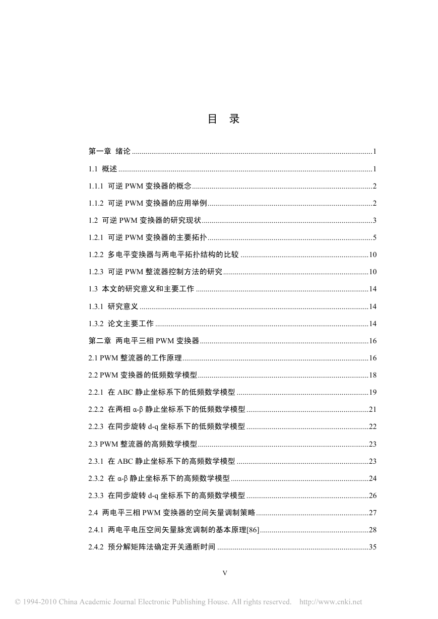
目 录
第一章 绪论 ............................................................................................................................1
1.1 概述 ...................................................................................................................................1
1.1.1 可逆 PWM 变换器的概念.............................................................................................2
1.1.2 可逆 PWM 变换器的应用举例.....................................................................................2
1.2 可逆 PWM 变换器的研究现状........................................................................................3
1.2.1 可逆 PWM 变换器的主要拓扑.....................................................................................5
1.2.2 多电平变换器与两电平拓扑结构的比较 ..................................................................10
1.2.3 可逆 PWM 整流器控制方法的研究...........................................................................10
1.3 本文的研究意义和主要工作 .........................................................................................14
1.3.1 研究意义 ......................................................................................................................14
1.3.2 论文主要工作 ..............................................................................................................14
第二章 两电平三相 PWM 变换器.......................................................................................16
2.1 PWM 整流器的工作原理................................................................................................16
2.2 PWM 变换器的低频数学模型........................................................................................18
2.2.1 在 ABC 静止坐标系下的低频数学模型 ....................................................................19
2.2.2 在两相 α-β 静止坐标系下的低频数学模型...............................................................21
2.2.3 在同步旋转 d-q 坐标系下的低频数学模型 ...............................................................22
2.3 PWM 整流器的高频数学模型........................................................................................23
2.3.1 在 ABC 静止坐标系下的高频数学模型 ....................................................................23
2.3.2 在 α-β 静止坐标系下的高频数学模型.......................................................................24
2.3.3 在同步旋转 d-q 坐标系下的高频数学模型 ...............................................................26
2.4 两电平三相 PWM 变换器的空间矢量调制策略..........................................................27
2.4.1 两电平电压空间矢量脉宽调制的基本原理[86]........................................................28
2.4.2 预分解矩阵法确定开关通断时间 ..............................................................................35
V
�


 2023年江西萍乡中考道德与法治真题及答案.doc
 2012年重庆南川中考生物真题及答案.doc
 2013年江西师范大学地理学综合及文艺理论基础考研真题.doc
 2020年四川甘孜小升初语文真题及答案I卷.doc
 2020年注册岩土工程师专业基础考试真题及答案.doc
 2023-2024学年福建省厦门市九年级上学期数学月考试题及答案.doc
 2021-2022学年辽宁省沈阳市大东区九年级上学期语文期末试题及答案.doc
 2022-2023学年北京东城区初三第一学期物理期末试卷及答案.doc
 2018上半年江西教师资格初中地理学科知识与教学能力真题及答案.doc
 2012年河北国家公务员申论考试真题及答案-省级.doc
 2020-2021学年江苏省扬州市江都区邵樊片九年级上学期数学第一次质量检测试题及答案.doc
 2022下半年黑龙江教师资格证中学综合素质真题及答案.doc