RM69330 Data Sheet
Rev:0.0
瑞 鼎 科 技 股 份 有 限 公 司
Raydium Semiconductor Corporation
RM69330 Data Sheet
Single Chip Driver with 16.7M color
for 480RGBx480 OLED driver
Revision:0.0
Date:Nov,01 2017
Attachment is the exclusive property of Raydium and shall not be reproduced or copied or transformed to any other format without prior
permission of Raydium. Please handle the information based on Non-Disclosure Agreement.
Page1
�
Revision History
Version
No.
Date
0.0
2017/11/01
First Release
RM69330 Data Sheet
Rev:0.0
Modified
Checked
By
Howard
Hsiung
By
CN.Lin
Description
Page
Attachment is the exclusive property of Raydium and shall not be reproduced or copied or transformed to any other format without prior
permission of Raydium. Please handle the information based on Non-Disclosure Agreement.
2
Page2
�
RM69330 Data Sheet
Rev:0.0
Table of Contents
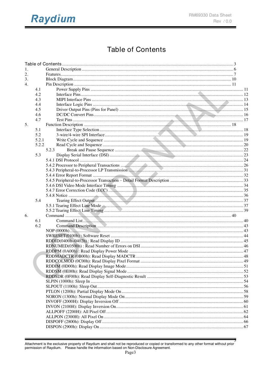
Table of Contents ........................................................................................................................................................... 3
General Description ......................................................................................................................................... 6
1.
Features ............................................................................................................................................................ 7
2.
3.
Block Diagram ............................................................................................................................................... 10
Pin Description .............................................................................................................................................. 11
4.
Power Supply Pins .......................................................................................................................................... 11
Interface Pins ................................................................................................................................................... 12
MIPI Interface Pins ......................................................................................................................................... 13
Interface Logic Pins ........................................................................................................................................ 14
Driver Output Pins (Pins for Panel) ................................................................................................................ 15
DC/DC Convert Pins ....................................................................................................................................... 16
Test Pins .......................................................................................................................................................... 17
5.
Function Description ..................................................................................................................................... 18
4.1
4.2
4.3
4.4
4.5
4.6
4.7
5.1
5.2
5.2.1
5.2.2
5.3
5.4
6.1
6.2
6.
5.2.3
Interface Type Selection .................................................................................................................................. 18
3-wire/4-wire SPI Interface ............................................................................................................................. 19
Write Cycle and Sequence .............................................................................................................................. 19
Read Cycle and Sequence ............................................................................................................................... 20
Break and Pause Sequence .................................................................................................................... 22
Display Serial Interface (DSI) ......................................................................................................................... 23
5.4.1 DSI Protocol .................................................................................................................................................... 24
5.4.2 Processor to Peripheral Transactions ............................................................................................................... 26
5.4.3 Peripheral-to-Processor LP Transmission ........................................................................................................ 31
5.4.4 Error Report Format ........................................................................................................................................ 32
5.4.5 Peripheral-to-Processor Transaction – Detail Format Description .................................................................. 33
5.4.6 DSI Video Mode Interface Timing .................................................................................................................. 34
5.4.7 Error Correction Code (ECC) .......................................................................................................................... 35
5.4.8 Notice .............................................................................................................................................................. 36
Tearing Effect Output ...................................................................................................................................... 37
5.5.1 Tearing Effect Line Mode ................................................................................................................................ 37
5.5.2 Tearing Effect Line Timing .............................................................................................................................. 39
Command ...................................................................................................................................................... 40
Command List ................................................................................................................................................. 40
Command Description .................................................................................................................................... 43
NOP (0000h) ............................................................................................................................................................. 43
SWRESET(0100h) : Software Reset ........................................................................................................................ 44
RDDID(0400h~0402h) : Read Display ID ............................................................................................................... 45
RDNUMED(0500h) : Read Number of Errors on DSI ............................................................................................. 46
RDDPM (0A00h) : Read Display Power Mode ....................................................................................................... 47
RDDMADCTR (0B00h): Read Display MADCTR ................................................................................................. 48
RDDCOLMOD (0C00h): Read Display Pixel Format ............................................................................................. 49
RDDIM (0D00h): Read Display Image Mode .......................................................................................................... 51
RDDSM (0E00h): Read Display Signal Mode ......................................................................................................... 52
RDDSDR (0F00h): Read Display Self-Diagnostic Result ....................................................................................... 53
SLPIN (1000h): Sleep In .......................................................................................................................................... 54
SLPOUT (1100h): Sleep Out .................................................................................................................................... 56
PTLON (1200h): Partial Display Mode On .............................................................................................................. 58
NORON (1300h): Normal Display Mode On ........................................................................................................... 59
INVOFF (2000H): Display Inversion Off ................................................................................................................ 60
INVON (2100H): Display Inversion On................................................................................................................... 61
ALLPOFF (2200H): All Pixel Off ............................................................................................................................ 62
ALLPON (2300H): All Pixel On .............................................................................................................................. 64
DISPOFF (2800h): Display Off ................................................................................................................................ 66
DISPON (2900h): Display On .................................................................................................................................. 67
Attachment is the exclusive property of Raydium and shall not be reproduced or copied or transformed to any other format without prior
permission of Raydium. Please handle the information based on Non-Disclosure Agreement.
3
Page3
�
RM69330 Data Sheet
Rev:0.0
7.
8.
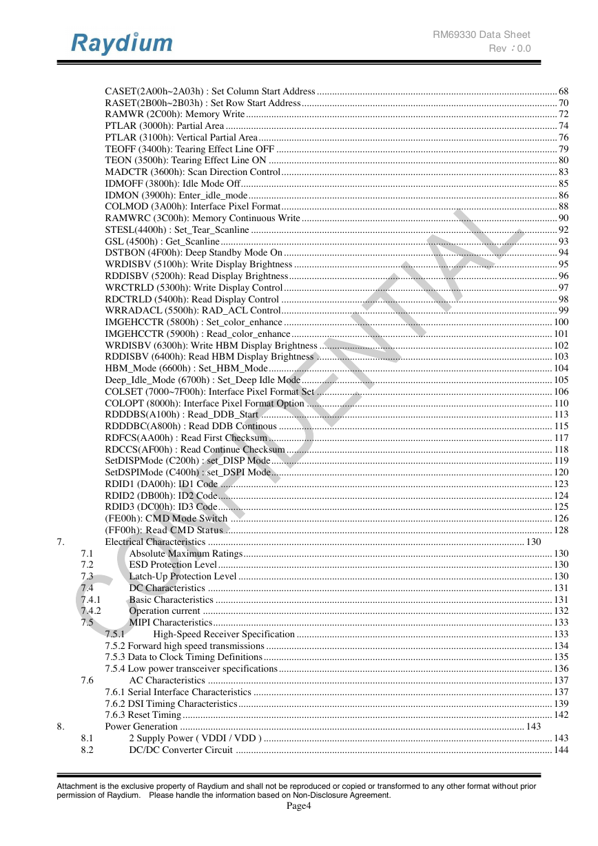
CASET(2A00h~2A03h) : Set Column Start Address ............................................................................................... 68
RASET(2B00h~2B03h) : Set Row Start Address ..................................................................................................... 70
RAMWR (2C00h): Memory Write ........................................................................................................................... 72
PTLAR (3000h): Partial Area ................................................................................................................................... 74
PTLAR (3100h): Vertical Partial Area ...................................................................................................................... 76
TEOFF (3400h): Tearing Effect Line OFF ............................................................................................................... 79
TEON (3500h): Tearing Effect Line ON .................................................................................................................. 80
MADCTR (3600h): Scan Direction Control ............................................................................................................. 83
IDMOFF (3800h): Idle Mode Off............................................................................................................................. 85
IDMON (3900h): Enter_idle_mode .......................................................................................................................... 86
COLMOD (3A00h): Interface Pixel Format ............................................................................................................. 88
RAMWRC (3C00h): Memory Continuous Write ..................................................................................................... 90
STESL(4400h) : Set_Tear_Scanline ......................................................................................................................... 92
GSL (4500h) : Get_Scanline ..................................................................................................................................... 93
DSTBON (4F00h): Deep Standby Mode On ............................................................................................................ 94
WRDISBV (5100h): Write Display Brightness ........................................................................................................ 95
RDDISBV (5200h): Read Display Brightness.......................................................................................................... 96
WRCTRLD (5300h): Write Display Control ............................................................................................................ 97
RDCTRLD (5400h): Read Display Control ............................................................................................................. 98
WRRADACL (5500h): RAD_ACL Control............................................................................................................. 99
IMGEHCCTR (5800h) : Set_color_enhance .......................................................................................................... 100
IMGEHCCTR (5900h) : Read_color_enhance ....................................................................................................... 101
WRDISBV (6300h): Write HBM Display Brightness ............................................................................................ 102
RDDISBV (6400h): Read HBM Display Brightness ............................................................................................. 103
HBM_Mode (6600h) : Set_HBM_Mode ................................................................................................................ 104
Deep_Idle_Mode (6700h) : Set_Deep Idle Mode ................................................................................................... 105
COLSET (7000~7F00h): Interface Pixel Format Set ............................................................................................. 106
COLOPT (8000h): Interface Pixel Format Option ................................................................................................. 110
RDDDBS(A100h) : Read_DDB_Start ................................................................................................................... 113
RDDDBC(A800h) : Read DDB Continous ............................................................................................................ 115
RDFCS(AA00h) : Read First Checksum ................................................................................................................ 117
RDCCS(AF00h) : Read Continue Checksum ......................................................................................................... 118
SetDISPMode (C200h) : set_DISP Mode ............................................................................................................... 119
SetDSPIMode (C400h) : set_DSPI Mode............................................................................................................... 120
RDID1 (DA00h): ID1 Code ................................................................................................................................... 123
RDID2 (DB00h): ID2 Code .................................................................................................................................... 124
RDID3 (DC00h): ID3 Code .................................................................................................................................... 125
(FE00h): CMD Mode Switch ............................................................................................................................... 126
(FF00h): Read CMD Status ................................................................................................................................. 128
Electrical Characteristics ............................................................................................................................. 130
Absolute Maximum Ratings.......................................................................................................................... 130
ESD Protection Level .................................................................................................................................... 130
Latch-Up Protection Level ............................................................................................................................ 130
DC Characteristics ........................................................................................................................................ 131
Basic Characteristics ..................................................................................................................................... 131
Operation current .......................................................................................................................................... 132
MIPI Characteristics...................................................................................................................................... 133
7.5.1
High-Speed Receiver Specification ..................................................................................................... 133
7.5.2 Forward high speed transmissions ................................................................................................................. 134
7.5.3 Data to Clock Timing Definitions .................................................................................................................. 135
7.5.4 Low power transceiver specifications ............................................................................................................ 136
AC Characteristics ........................................................................................................................................ 137
7.6.1 Serial Interface Characteristics ...................................................................................................................... 137
7.6.2 DSI Timing Characteristics ............................................................................................................................ 139
7.6.3 Reset Timing .................................................................................................................................................. 142
Power Generation ........................................................................................................................................ 143
2 Supply Power ( VDDI / VDD ) .................................................................................................................. 143
DC/DC Converter Circuit ............................................................................................................................. 144
7.1
7.2
7.3
7.4
7.4.1
7.4.2
7.5
7.6
8.1
8.2
Attachment is the exclusive property of Raydium and shall not be reproduced or copied or transformed to any other format without prior
permission of Raydium. Please handle the information based on Non-Disclosure Agreement.
Page4
�
9.
8.3
8.4
8.5
8.6
External Components .................................................................................................................................... 145
Power on/off sequence and timing ................................................................................................................ 146
Power Level Modes....................................................................................................................................... 147
Maximum Series Resistance ......................................................................................................................... 148
Pad Diagram and Coordination ................................................................................................................... 149
RM69330 Data Sheet
Rev:0.0
Attachment is the exclusive property of Raydium and shall not be reproduced or copied or transformed to any other format without prior
permission of Raydium. Please handle the information based on Non-Disclosure Agreement.
Page5
�
RM69330 Data Sheet
Rev:0.0
1. General Description
The RM69330 device is a single-chip solution for LTPS AMOLED that incorporates gate drivers and is
capable of 480RGBx480, 400RGBx400, 360RGBx480, 320RGBx320, 320RGBx480, 272RGBx480,
240RGBx240, 240RGBx320, 180RGBx360, 180RGBx540, 128RGBx432with internal GRAM. It includes a
2,764,800 bits internal memory, a timing controller with glass interface level-shifters and a glass power supply
circuit.
The RM69330 supports MIPI Interface, 8-bit system interfaces, serial peripheral interfaces (SPI), dual serial
peripheral interfaces (Dual-SPI). The specified window area can be updated selectively, so that moving
pictures can be displayed simultaneously independent of the still picture area.
The RM69330 is also able to make gamma correction settings separately for RGB dots to allow benign
adjustments to panel characteristics, resulting in higher display qualities. The IC possesses internal GRAM
that stores 480 x 480 x 1/2 x 24 bits for 16.77M-color images. A deep standby mode is also supported for
lower power consumption.
This LSI is suitable for wearable device applications, including I-watch and smart band.
Attachment is the exclusive property of Raydium and shall not be reproduced or copied or transformed to any other format without prior
permission of Raydium. Please handle the information based on Non-Disclosure Agreement.
Page6
�
2. Features
Single chip AMOLED controller/driver with display RAM
Display resolution option
RM69330 Data Sheet
Rev:0.0
480RGB x 480
400RGB x 400
360RGB x 480
320RGB x 320
320RGB x 480
272RGB x 480
240RGB x 240
240RGB x 320
180RGB x 360
180RGB x 540
128RGB x 432
Display data RAM (frame memory): 2,764,800 bits
Display mode (Color mode)
Full color mode: 16.7M-colors
Idle mode: 16.7M-colors, 4096-colors, 8-colors
Interface
8-bits 80-series MPU interface
Serial peripheral interface (SPI)
Dual serial peripheral interface (Dual-SPI)
MIPI Display Serial Interface (1 clock and 2 data lane pairs)
Support 1lane/2lane (1lane: 500Mbps)
Maximum total bit rate is 500Mbps of 2 data lanes 24-bit data format/ 360Mbps of 2 data
lanes 18-bit data format/ 320Mbps of 2 data lanes 16-bit data format
Abundant color display and drawing functions
Programmable γ-correction function for 16.7 million color display
Individual gamma correction setting for RGB dots
Partial display function
Sunlight readable
Control power IC by one-wire interface
On chip
VREFP5/VREFN5 voltage generator for panel voltage
VGHR/VGLR voltage for gate control signal
Internal oscillator for display clock
Source output MUX 1-6 with 240ch source output pins
Supports gate control signals to gate driver in the panel
Built-in OTP function to adjust panel setting
Logic / interface power supply voltage VDDI = 1.65V ~ 3.3V
Analog power supply voltage VDD = 2.7V ~ 3.6V
Attachment is the exclusive property of Raydium and shall not be reproduced or copied or transformed to any other format without prior
permission of Raydium. Please handle the information based on Non-Disclosure Agreement.
Page7
�
RM69330 Data Sheet
Rev:0.0
Output voltage levels
Positive gate driver voltage range for VGHR: 3 ~ 10.5V (Max<=VGH-0.3v)
Negative gate driver voltage range for VGLR: -2V ~ -9.5V (Min>=VGL+0.3v)
VREFP5 panel voltage range : 0~5V (Max<=AVDD-0.3v)
VREFN5 panel voltage range : -0.5~-4.5V (Min>=VCL+0.3v)
Step-up 1,2 output voltage range for AVDD: 4.5 ~ 6.5V, VCL: -3.5 ~ -5.0V
Gamma high/low voltage range for VGMP: 2.0V ~ 6.0V (Max<=AVDD-0.5v) , VGSP: 0V, 0.2125V ~
4.5V
Package: COF/COG
Chip size evaluation : 8300um x 2060um(including scribe line)
Attachment is the exclusive property of Raydium and shall not be reproduced or copied or transformed to any other format without prior
permission of Raydium. Please handle the information based on Non-Disclosure Agreement.
Page8
�


 2023年江西萍乡中考道德与法治真题及答案.doc
 2012年重庆南川中考生物真题及答案.doc
 2013年江西师范大学地理学综合及文艺理论基础考研真题.doc
 2020年四川甘孜小升初语文真题及答案I卷.doc
 2020年注册岩土工程师专业基础考试真题及答案.doc
 2023-2024学年福建省厦门市九年级上学期数学月考试题及答案.doc
 2021-2022学年辽宁省沈阳市大东区九年级上学期语文期末试题及答案.doc
 2022-2023学年北京东城区初三第一学期物理期末试卷及答案.doc
 2018上半年江西教师资格初中地理学科知识与教学能力真题及答案.doc
 2012年河北国家公务员申论考试真题及答案-省级.doc
 2020-2021学年江苏省扬州市江都区邵樊片九年级上学期数学第一次质量检测试题及答案.doc
 2022下半年黑龙江教师资格证中学综合素质真题及答案.doc