通用寄存器组实验报告
一、 实验目的
1、 了解通用寄存器组的用途及对 CPU 的重要性。
2、 掌握通用寄存器组的设计方法。
二、 实验原理
通用寄存器组是 CPU 的重要组成部分。由于从通用寄存器组中取数据比从
存储器或者外部设备取数据快得多,因此参加算术运算和逻辑运算的数据一般是
从通用寄存器组中取出,它向算术逻辑单元 ALU 提供了进行算术运算和逻辑运
算所需要的两个操作数,同时又是运算结果的暂存地。通用寄存器组内寄存器的
数目与 CPU 性能有关,CPU 性能预告,通用寄存器组内的寄存器数目越多。由
于算术逻辑运算需要两个操作数,因此通用寄存器组有两个读端口,负责提供进
行算术逻辑单元需要的源操作数和目的操作数。通用寄存器组有 1 个写端口,负
责将运算结果保存到指定的寄存器内。根据通用寄存器组的功能要求,一个只有
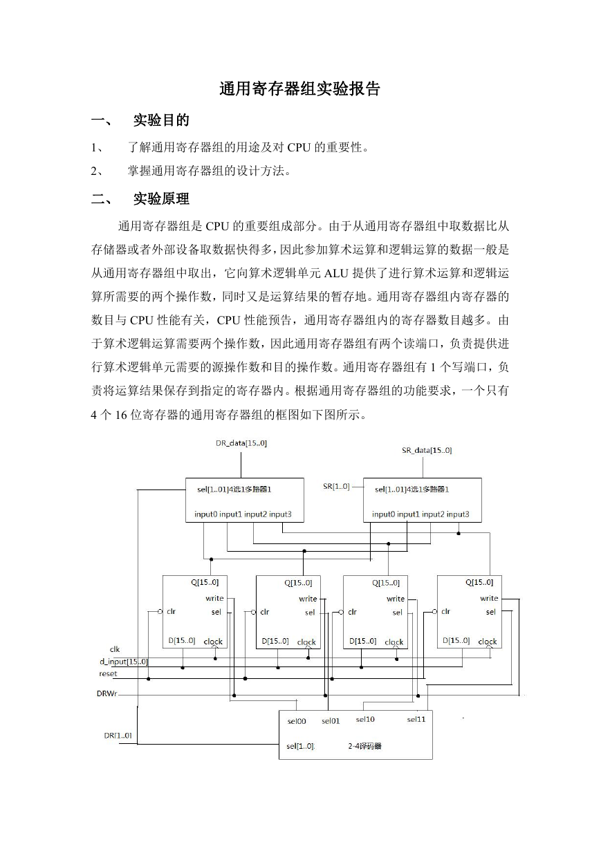
4 个 16 位寄存器的通用寄存器组的框图如下图所示。
�
在上图所示的电路中,当 reset 为低电平时,将 4 个 16 位寄存器 R0~R3 复
位为 0。当寄存器的 write 和 sel 为高电平时,在时钟信号 clk 的上升沿将 D 端的
输入 D[15..0]写入寄存器,然后送到寄存器的输出 Q[15..0]。4 个寄存器的允许写
信号 write 和外部产生的目的寄存器写信号 DRWr 直接相连。每个寄存器还有另
一个选择信号 sel,它决定哪一个寄存器进行写操作。4 个寄存器的选择信号分
别和 2-4 译码器产生的 sel00、sel01、sel10 和 sel11 相连。只有当 1 个寄存器被
选中时,才允许对该寄存器进行写操作。2-4 译码器的输入 sel[1..0]接 DR[1..0],
2-4 译码器对 2 位的输入信号 sel[1..0]进行 2-4 译码,产生 4 个输出 sel00、sel01、
sel10 和 sel11,分别送往 4 个寄存器 R0、R1、R2、R3 的选择端 4 选 1 多路选择
器 1 从 4 个寄存器 R0、R1、R2、R3 的输出 Q[15..0]选择 1 路送到 DR_data[1..0],
给算术逻辑单元提供目的操作数;选择信号 sel[1..0]接 DR[1..0]。4 选 1 多路选择
器 2 从 4 个寄存器 R0、R1、R2、R3 的输出 Q[15..0]选择一路送到 SR_data[1..0],
给算术逻辑单元提供源操作数;选择信号 sel[1..0]接 SR[1..0]。
三、实验要求
1、实验设计目标
(1) 通用寄存器组有 4 个 16 位的寄存器。
(2) 当复位信号 reset=0 时,将通用寄存器组中的 4 个寄存器清零。
(3) 通用寄存器组中有 1 个写入端口,当 DRWr=1 时,在时钟 clk 的上升沿
将数据总线上的数写入 DR[1..0]指定的寄存器。
(4) 通用寄存器组中有两个读出端口,一个对应算术逻辑单元的目的操作数
DR,另一个对应算术逻辑单元的源操作数 SR。DR[1..0]选择目的操作数;SR[1..0]
选择源操作数。
(5) 设计要求层次设计。底层的设计实体有 3 个:16 位寄存器,具有复位功
能和允许写功能;一个 2-4 译码器,对应寄存器写选择;一个 4 选 1 多路开关,
负责选择寄存器的读出。顶层设计构成一个完整的通用寄存器组。
2、顶层设计实体的引脚连接
(1) clk 对应实验台上的时钟(单脉冲)。
(2) reset 对应试验台上的 CPU 复位信号 CPU-RST。
(3) SR[1...0]对应试验台开关 SA1,SA0。
�
(4) DR[1..0]对应试验台开关 SA3,SA2。
(5) DRWr 对应试验台开关 SA5。
(6) 目的操作数用实验台上的指示灯 A15~A0 显示,源操作数用试验台
上的指示灯 R15~R0 显示。
(7) d_input 对应实验台开关 SD15~SD0。
四、 实验步骤及结果
1、将实验台设置成 FPGA-CPU 独立调试模式,REGSEL=0、CLKSEL=1、
FDSEL=0。使用试验台上的单脉冲,即DTEP_CLK 短路子短接,短路子RUN_CLK
断开。
2、将涉及在 QuartusII 下输入,编译后下载到 TEC_CA 上的 FPGA 中。
3、将下列数据存入寄存器:
R0 0x3333
R1 0x5555
R2 0xAAAA
R3 0xFFFF
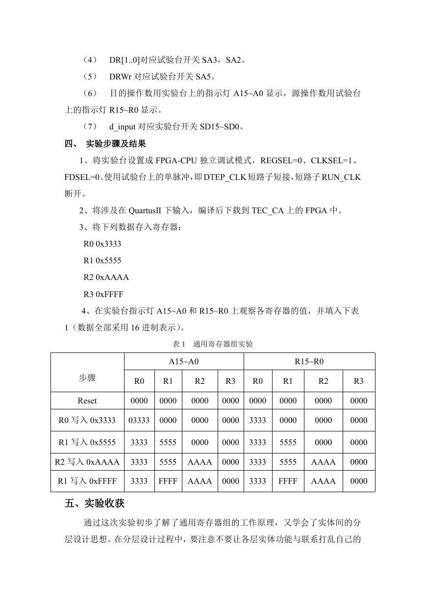
4、在实验台指示灯 A15~A0 和 R15~R0 上观察各寄存器的值,并填入下表
1(数据全部采用 16 进制表示)。
表 1 通用寄存器组实验
A15~A0
R15~R0
步骤
Reset
R0
R1
0000
0000
R0 写入 0x3333
03333
0000
R2
0000
0000
R3
R0
0000
0000
0000
3333
R1 写入 0x5555
3333
5555
0000
0000
3333
R2 写入 0xAAAA 3333
5555 AAAA 0000
3333
R1
0000
0000
5555
5555
R2
0000
0000
0000
AAAA
R1 写入 0xFFFF
3333
FFFF AAAA 0000
3333
FFFF
AAAA
R3
0000
0000
0000
0000
0000
五、实验收获
通过这次实验初步了解了通用寄存器组的工作原理,又学会了实体间的分
层设计思想。在分层设计过程中,要注意不要让各层实体功能与联系打乱自己的
�
思维。底层实体各自完成自己的功能,供顶层实体通过输入输出引脚总体调度连
接使用。
library ieee;
use ieee.std_logic_1164.all;
entity reg is
port(
clock,sel,w,clr : in std_logic;
D:in std_logic_vector(15 downto 0);
Q:out std_logic_vector(15 downto 0)
);
end entity;
architecture rtl of reg is
begin
process(clock,clr)
begin
if(clock'event and clock='1')then
if(w='1' and sel='1')then
Q(15 downto 0)<=D(15 downto 0);
end if;
end if;
if(clr='0')then
Q(15 downto 0)<="0000000000000000";
end if;
end process;
end rtl;
library ieee;
use ieee.std_logic_1164.all;
entity t2_4 is
port(
sel:in std_logic_vector(1 downto 0);
sel00,sel01,sel10,sel11:out std_logic
);
end entity;
architecture rtl of t2_4 is
begin
sel00<=(not sel(1)) and (not sel(0));
sel01<=(not sel(1)) and
sel(0);
sel10<= sel(1) and (not sel(0));
�
sel11<= sel(1) and
sel(0);
end rtl;
library ieee;
use ieee.std_logic_1164.all;
entity R4_to_1 is
port(
input0,input1,input2,input3:in std_logic_vector(15 downto 0);
sel:in std_logic_vector(1 downto 0);
R_data:out std_logic_vector(15 downto 0)
);
end entity;
architecture rtl of R4_to_1 is
begin
process(input0,input1,input2,input3,sel)
begin
case sel is
when "00"=>R_data<=input0;
when "01"=>R_data<=input1;
when "10"=>R_data<=input2;
when "11"=>R_data<=input3;
end case;
end process;
end rtl;
library ieee;
use ieee.std_logic_1164.all;
entity registers is
port(
clk,reset,DRWr:in std_logic;
DR,SR:in std_logic_vector(1 downto 0);
d_input:in std_logic_vector(15 downto 0);
DR_data,SR_data:out std_logic_vector(15 downto 0)
);
end entity;
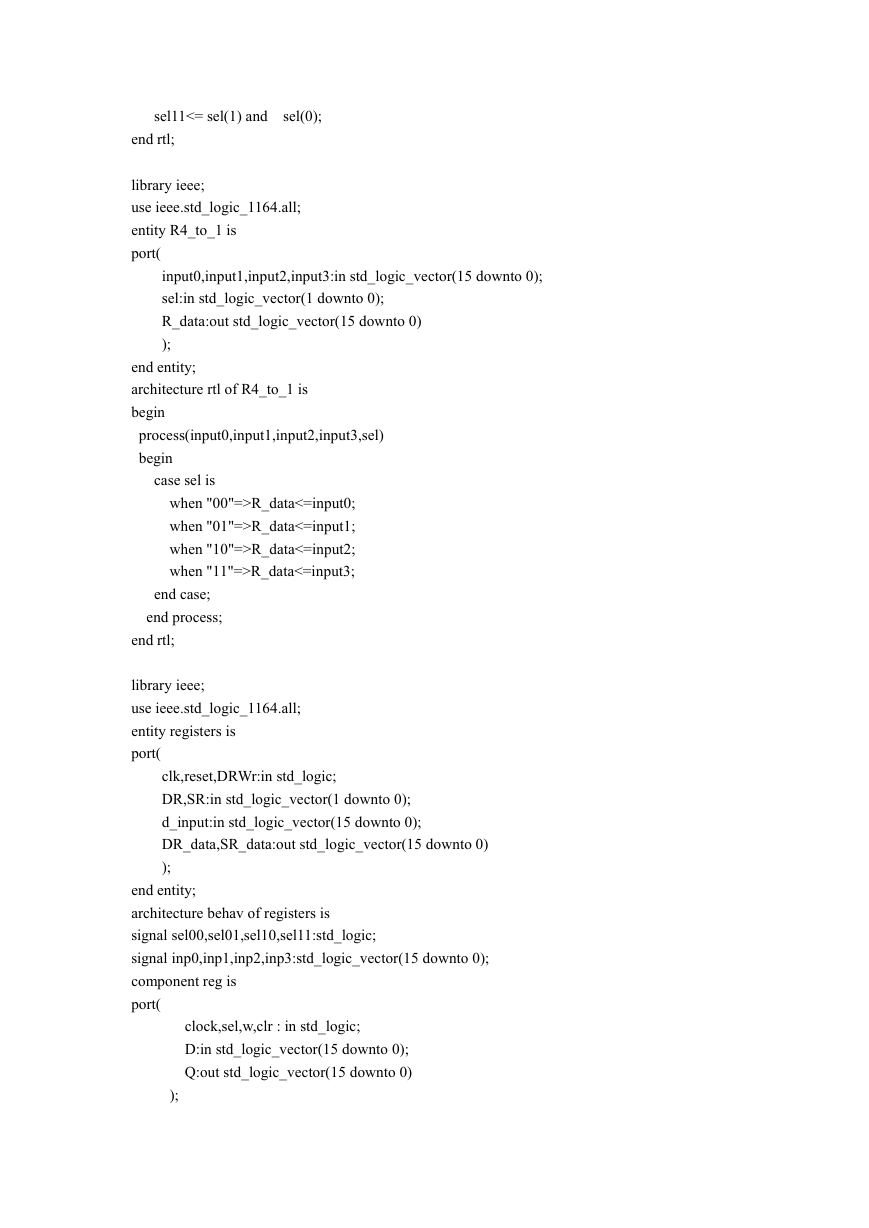
architecture behav of registers is
signal sel00,sel01,sel10,sel11:std_logic;
signal inp0,inp1,inp2,inp3:std_logic_vector(15 downto 0);
component reg is
port(
clock,sel,w,clr : in std_logic;
D:in std_logic_vector(15 downto 0);
Q:out std_logic_vector(15 downto 0)
);
�
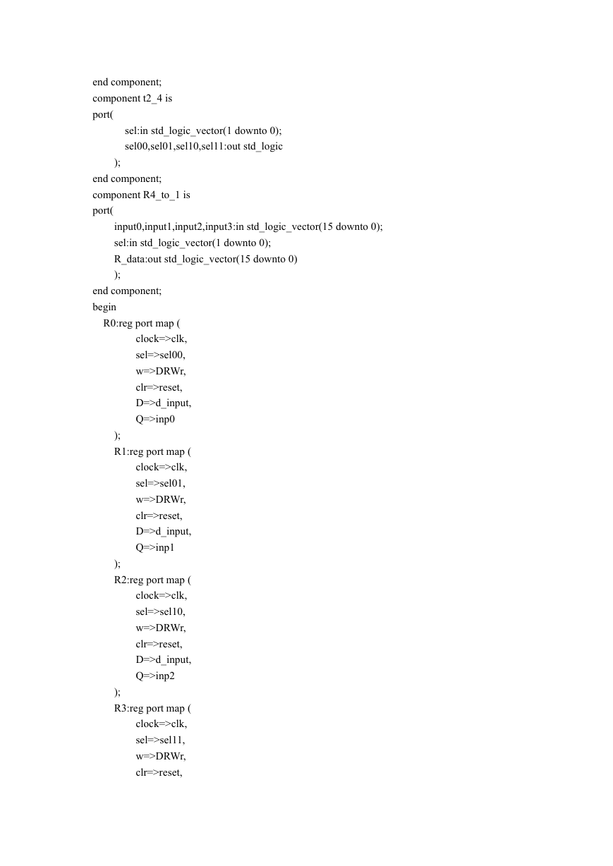
end component;
component t2_4 is
port(
sel:in std_logic_vector(1 downto 0);
sel00,sel01,sel10,sel11:out std_logic
);
end component;
component R4_to_1 is
port(
input0,input1,input2,input3:in std_logic_vector(15 downto 0);
sel:in std_logic_vector(1 downto 0);
R_data:out std_logic_vector(15 downto 0)
);
end component;
begin
R0:reg port map (
clock=>clk,
sel=>sel00,
w=>DRWr,
clr=>reset,
D=>d_input,
Q=>inp0
);
R1:reg port map (
clock=>clk,
sel=>sel01,
w=>DRWr,
clr=>reset,
D=>d_input,
Q=>inp1
);
R2:reg port map (
clock=>clk,
sel=>sel10,
w=>DRWr,
clr=>reset,
D=>d_input,
Q=>inp2
);
R3:reg port map (
clock=>clk,
sel=>sel11,
w=>DRWr,
clr=>reset,
�
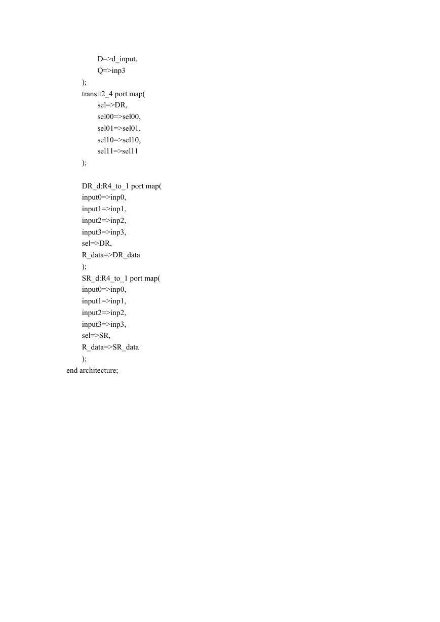
D=>d_input,
Q=>inp3
);
trans:t2_4 port map(
sel=>DR,
sel00=>sel00,
sel01=>sel01,
sel10=>sel10,
sel11=>sel11
);
DR_d:R4_to_1 port map(
input0=>inp0,
input1=>inp1,
input2=>inp2,
input3=>inp3,
sel=>DR,
R_data=>DR_data
);
SR_d:R4_to_1 port map(
input0=>inp0,
input1=>inp1,
input2=>inp2,
input3=>inp3,
sel=>SR,
R_data=>SR_data
);
end architecture;
�


 2023年江西萍乡中考道德与法治真题及答案.doc
 2012年重庆南川中考生物真题及答案.doc
 2013年江西师范大学地理学综合及文艺理论基础考研真题.doc
 2020年四川甘孜小升初语文真题及答案I卷.doc
 2020年注册岩土工程师专业基础考试真题及答案.doc
 2023-2024学年福建省厦门市九年级上学期数学月考试题及答案.doc
 2021-2022学年辽宁省沈阳市大东区九年级上学期语文期末试题及答案.doc
 2022-2023学年北京东城区初三第一学期物理期末试卷及答案.doc
 2018上半年江西教师资格初中地理学科知识与教学能力真题及答案.doc
 2012年河北国家公务员申论考试真题及答案-省级.doc
 2020-2021学年江苏省扬州市江都区邵樊片九年级上学期数学第一次质量检测试题及答案.doc
 2022下半年黑龙江教师资格证中学综合素质真题及答案.doc