Chapter
16
Advanced Visual Servoing
This chapter builds on the previous one and introduces some advanced visual servo
techniques and applications. Section 16.1 introduces a hybrid visual servo method
that avoids some of the limitations of the IBVS and PBVS schemes described pre-
viously.
Wide-angle cameras such as fisheye lenses and catadioptric cameras have signifi-
cant advantages for visual servoing. Section 16.2 shows how IBVS can be reformulated
for polar rather than Cartesian image-plane coordinates. This is directly relevant to
fisheye lenses but also gives improved rotational control when using a perspective
camera. The unified imaging model from Sect. 11.4 allows most cameras (perspective,
fisheye and catadioptric) to be represented by a spherical projection model, and
Sect. 16.3 shows how IBVS can reformulated for spherical coordinates.
The remaining sections present a number of application examples. These illus-
trate how visual servoing can be used with different types of cameras (perspective
and spherical) and different types of robots (arm-type robots, mobile ground robots
and flying robots). Section 16.4 considers a 6 degree of freedom robot arm manipu-
lating the camera. Section 16.5 considers a mobile robot moving to a specific pose
which could be used for navigating through a doorway or docking. Finally, Sect. 16.6
considers visual servoing of a quadcopter flying robot to hover at fixed pose with
respect to a target on the ground.
16.1
lXY/Z-Partitioned IBVS
In the last chapter we encountered the problem of camera retreat in an IBVS system.
This phenomenon can be explained intuitively by the fact that our IBVS control law
causes feature points to move in straight lines on the image plane, but for a rotating
camera the points will naturally move along circular arcs. The linear IBVS controller
dynamically changes the overall image scale so that motion along an arc appears as
motion along a straight line. The scale change is achieved by z-axis translation.
Partitioned methods eliminate camera retreat by using IBVS to control some de-
grees of freedom while using a different controller for the remaining degrees of freedom.
The XY/Z hybrid schemes consider the x- and y-axes as one group, and the z-axes as
another group. The approach is based on a couple of insights. Firstly, and intuitively,
the camera retreat problem is a z-axis phenomenon: z-axis rotation leads to unwanted
z-axis translation. Secondly, from Fig. 15.7, the image plane motion due to x- and y-axis
translational and rotation motion are quite similar, whereas the optical flow due to z-axis
rotation and translation are radically different.
We partition the point-feature optical flow of Eq. 15.7 so that
(16.1)
where νxy = (vx, vy, ω
z), and Jxy and Jz are respectively columns {1, 2, 4, 5}
and {3, 6} of Jp. Since νz will be computed by a different controller we can write Eq. 16.1 as
y), νz = (vz, ω
x, ω
�
482
Chapter 16 · Advanced Visual Servoing
Fig. 16.1.
Image features for XY /Z parti-
tioned IBVS control. As well as
the coordinates of the four
points (blue dots), we use the
polygon area A and the angle
of the longest line segment θ
(16.2)
where
The z-axis velocities vz and ω
¹
* is the desired feature point velocity as in the traditional IBVS scheme Eq. 15.10.
z are computed directly from two additional image
features A and θ that shown in Fig. 16.1. The first image feature θ ∈ [0, 2π), is the angle
between the u-axis and the directed line segment joining feature points i and j. For
numerical conditioning it is advantageous to select the longest line segment that can
be constructed from the feature points, and allowing that this may change during the
motion as the feature point configuration changes. The desired rotational rate is ob-
tained using a simple proportional control law
Rotationally invariant to rotation about
the z-axis, not the x- and y-axes.
where the operator indicates modulo-2π subtraction. As always with motion on a
circle there are two directions to move to achieve the goal. If the rotation is limited, for
instance by a mechanical stop, then the sign of ω
z should be chosen so as to avoid
motion through that stop.
The second image feature that we use is a function of the area A of the regular
polygon whose vertices are the image feature points. The advantages of this measure
are: it is a scalar; it is rotation invariant thus decoupling camera rotation from
Z-axis translation; and it can be cheaply computed. The area of the polygon is just the
zeroth-order moment, m00 which can be computed using the Toolbox function
mpq_poly(p, 0, 0). The feature for control is the square root of area
which has units of length, in pixels. The desired camera z-axis translation rate is ob-
tained using a simple proportional control law
(16.3)
The features discussed above for z-axis translation and rotation control are simple
and inexpensive to compute, but work best when the target normal is within ±40° of
the camera’s optical axis. When the target plane is not orthogonal to the optical axis its
area will appear diminished, due to perspective, which causes the camera to initially
approach the target. Perspective will also change the perceived angle of the line seg-
ment which can cause small, but unnecessary, z-axis rotational motion.
The Simulink® model
>> sl_xyzpartitioned
is shown in Fig. 16.2. The initial pose of the camera is set by a parameter of the pose
block. The simulation is run by
�
16.1 · XY/Z-Partitioned IBVS
483
Fig. 16.2. The Simulink® model
sl_partitioned is an XY /Z-
partitioned visual servo scheme,
an extension of the IBVS system
shown in Fig. 15.9. The initial
camera pose is set in the pose
block and the desired image plane
* are set in the green con-
points p
stant block
>> sim('sl_partitioned')
and the camera pose, image plane feature error and camera velocity are animated.
Scope blocks also plot the camera velocity and feature error against time.
If points are moving toward the edge of the field of view the simplest way to keep them
in view is to move the camera away from the scene. We define a repulsive force that acts on
the camera, pushing it away as a point approaches the boundary of the image plane
where d(p) is the shortest distance to the edge of the image plane from the image
point p, and d0 is the width of the image zone in which the repulsive force acts, and
η is a scalar gain coefficient. For a W × H image
(16.4)
The repulsion force is incorporated into the z-axis translation controller
where η is a gain constant with units of damping. The repulsion force is discontinuous
and may lead to chattering where the feature points oscillate in and out of the repul-
sive force – this can be remedied by introducing smoothing filters and velocity limiters.
�
484
Chapter 16 · Advanced Visual Servoing
16.2
lIBVS Using Polar Coordinates
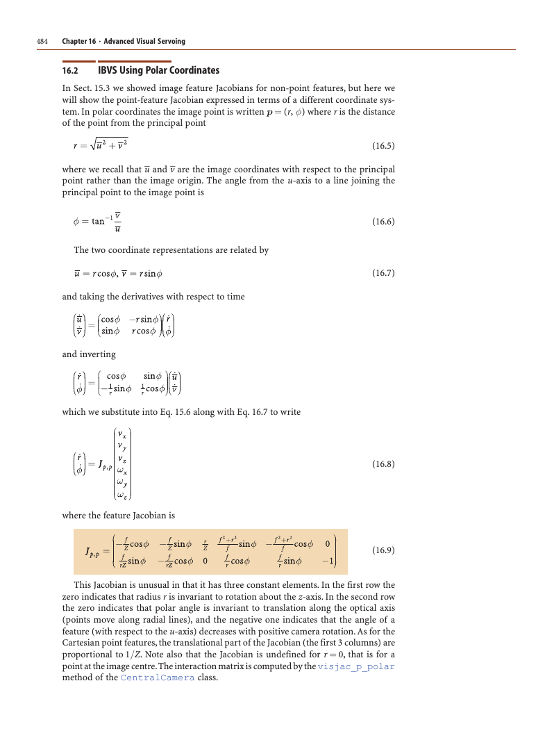
In Sect. 15.3 we showed image feature Jacobians for non-point features, but here we
will show the point-feature Jacobian expressed in terms of a different coordinate sys-
tem. In polar coordinates the image point is written p = (r, φ) where r is the distance
of the point from the principal point
where we recall that –u and –v are the image coordinates with respect to the principal
point rather than the image origin. The angle from the u-axis to a line joining the
principal point to the image point is
(16.5)
The two coordinate representations are related by
and taking the derivatives with respect to time
and inverting
which we substitute into Eq. 15.6 along with Eq. 16.7 to write
where the feature Jacobian is
(16.6)
(16.7)
(16.8)
(16.9)
This Jacobian is unusual in that it has three constant elements. In the first row the
zero indicates that radius r is invariant to rotation about the z-axis. In the second row
the zero indicates that polar angle is invariant to translation along the optical axis
(points move along radial lines), and the negative one indicates that the angle of a
feature (with respect to the u-axis) decreases with positive camera rotation. As for the
Cartesian point features, the translational part of the Jacobian (the first 3 columns) are
proportional to 1/Z. Note also that the Jacobian is undefined for r = 0, that is for a
point at the image centre. The interaction matrix is computed by the visjac_p_polar
method of the CentralCamera class.
�
16.2 · IBVS Using Polar Coordinates
485
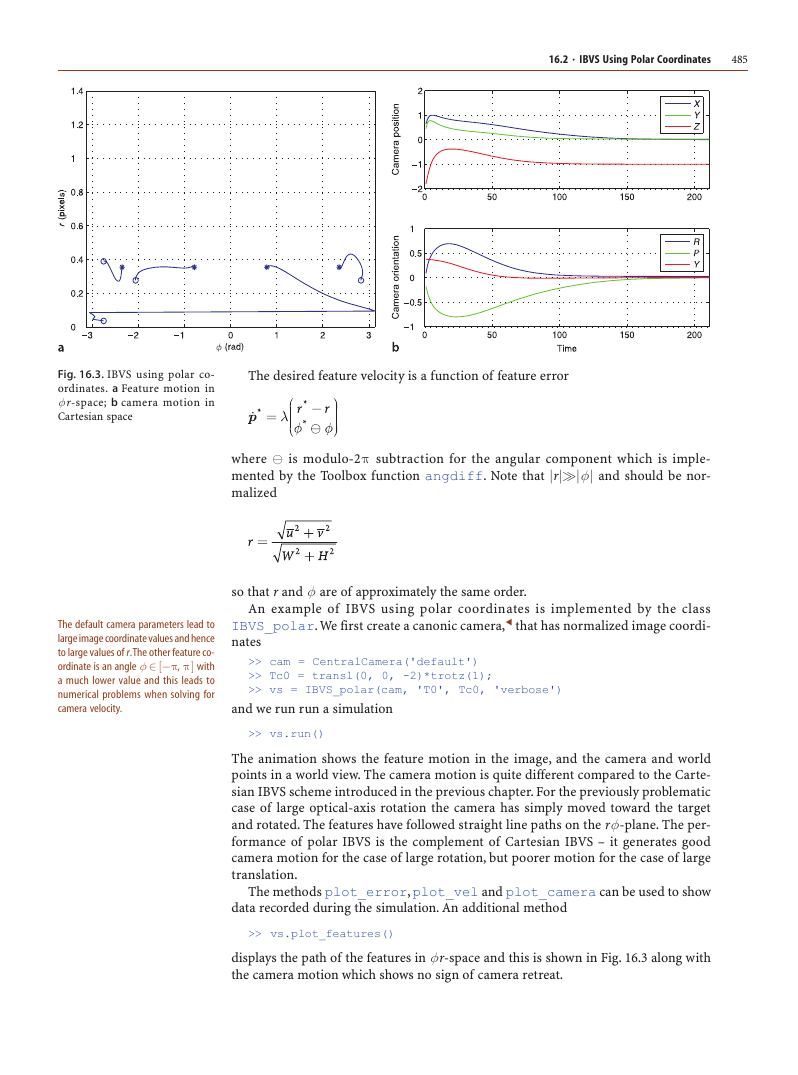
Fig. 16.3. IBVS using polar co-
ordinates. a Feature motion in
φ r-space; b camera motion in
Cartesian space
The desired feature velocity is a function of feature error
where is modulo-2π subtraction for the angular component which is imple-
mented by the Toolbox function angdiff. Note that |r||φ | and should be nor-
malized
The default camera parameters lead to
large image coordinate values and hence
to large values of r. The other feature co-
ordinate is an angle φ ∈ [−π, π ] with
a much lower value and this leads to
numerical problems when solving for
camera velocity.
so that r and φ are of approximately the same order.
An example of IBVS using polar coordinates is implemented by the class
IBVS_polar. We first create a canonic camera, that has normalized image coordi-
nates
>> cam = CentralCamera('default')
>> Tc0 = transl(0, 0, -2)*trotz(1);
>> vs = IBVS_polar(cam, 'T0', Tc0, 'verbose')
and we run run a simulation
>> vs.run()
The animation shows the feature motion in the image, and the camera and world
points in a world view. The camera motion is quite different compared to the Carte-
sian IBVS scheme introduced in the previous chapter. For the previously problematic
case of large optical-axis rotation the camera has simply moved toward the target
and rotated. The features have followed straight line paths on the rφ-plane. The per-
formance of polar IBVS is the complement of Cartesian IBVS – it generates good
camera motion for the case of large rotation, but poorer motion for the case of large
translation.
The methods plot_error, plot_vel and plot_camera can be used to show
data recorded during the simulation. An additional method
>> vs.plot_features()
displays the path of the features in φr-space and this is shown in Fig. 16.3 along with
the camera motion which shows no sign of camera retreat.
�
486
Chapter 16 · Advanced Visual Servoing
16.3
lIBVS for a Spherical Camera
In Sect. 11.3 we looked at non-perspective cameras such as the fisheye lens camera
and the catadioptric camera. Given the particular projection equations we can derive
an image-feature Jacobian from first principles. However the many different lens and
mirror shapes leads to many different projection models and image Jacobians. Alter-
natively we can project the features from any type of camera to the sphere, Sect. 11.5.1,
and derive an image Jacobian for visual servo control on the sphere.
The image Jacobian for the sphere is derived in a manner similar to the perspective
camera in Sect. 15.2.1. Referring to Fig. 11.20 the world point P is represented by the
vector P = (X, Y, Z) in the camera frame, and is projected onto the surface of the sphere
at the point p = (x, y, z) by a ray passing through the centre of the sphere
(16.10)
_
(X 2
gg
g
Z
+
where R =
gg
g
Y 2
+
g
2) is the distance from the camera origin to the world point.
The spherical surface constraint x2 + y2 + z2 = 1 means that one of the Cartesian
coordinates is redundant so we will use a minimal spherical coordinate system com-
prising the angle of colatitude
where r = √
⎯
x2
⎯
+
⎯
y 2, and the azimuth angle (or longitude)
(16.11)
(16.12)
which yields the point feature vector p = (θ, φ).
Taking the derivatives of Eq. 16.11 and Eq. 16.12 with respect to time and substitut-
ing Eq. 15.2 as well as
we obtain, in matrix form, the spherical optical flow equation
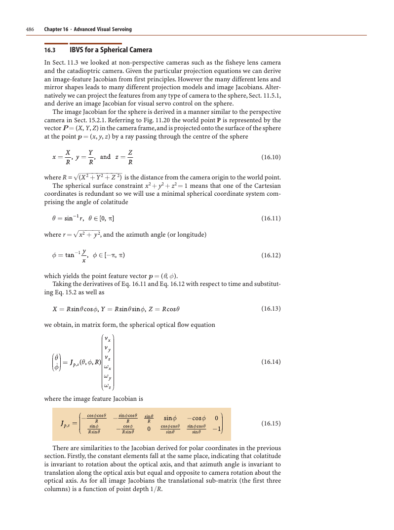
where the image feature Jacobian is
(16.13)
(16.14)
(16.15)
There are similarities to the Jacobian derived for polar coordinates in the previous
section. Firstly, the constant elements fall at the same place, indicating that colatitude
is invariant to rotation about the optical axis, and that azimuth angle is invariant to
translation along the optical axis but equal and opposite to camera rotation about the
optical axis. As for all image Jacobians the translational sub-matrix (the first three
columns) is a function of point depth 1/R.
�
16.3 · IBVS for a Spherical Camera
487
The Jacobian is not defined at the north and south poles where sin θ = 0 and azi-
muth also has no meaning at these points. This is a singularity, and as we remarked in
Sect. 2.2.1.3, in the context of Euler angle representation of orientation, this is a conse-
quence of using a minimal representation. However, in general the benefits outweigh
the costs for this application.
For control purposes we follow the normal procedure of computing one 2 × 6 Jaco-
bian, Eq. 8.2, for each of N feature points and stacking them to form a 2N × 6 matrix
The control law is
(16.16)
(16.17)
¹
* is the desired velocity of the features in φ θ -space. Typically we choose this to
where
be proportional to feature error
(16.18)
Note that motion on this plane is in gen-
eral not a great circle on the sphere –
only motion along lines of colatitude and
the equator are great circles.
* the desired
where λ is a positive gain, p is the current point in φ θ -coordinates, and p
value. This results in locally linear motion of features within the feature space.
denotes modulo subtraction and returns the smallest angular distance given that
θ ∈ [0, π] and φ = [−π, π).
An example of IBVS using spherical coordinates (Fig. 16.4) is implemented by the
class IBVS_sph. We first create a spherical camera
>> cam = SphericalCamera()
and then a spherical IBVS object
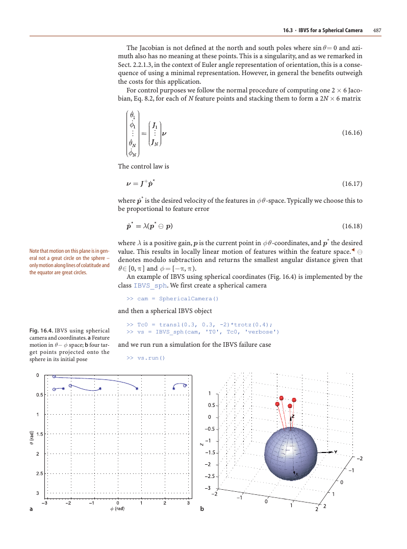
Fig. 16.4. IBVS using spherical
camera and coordinates. a Feature
motion in θ − φ space; b four tar-
get points projected onto the
sphere in its initial pose
>> Tc0 = transl(0.3, 0.3, -2)*trotz(0.4);
>> vs = IBVS_sph(cam, 'T0', Tc0, 'verbose')
and we run run a simulation for the IBVS failure case
>> vs.run()
�
488
Chapter 16 · Advanced Visual Servoing
The animation shows the feature motion on the φ θ -plane and the camera and world
points in a world view. Spherical imaging has many advantages for visual servoing.
Firstly, a spherical camera eliminates the need to explicitly keep features in the field of
view which is a problem with both position-based visual servoing and some hybrid
schemes. Secondly, we previously observed an ambiguity between the optical flow fields
for Rx and −Ty motion (and Ry and −Tx motion) for small field of view. For IBVS with
a long focal length this can lead to slow convergence and/or sensitivity to noise in
feature coordinates. For a spherical camera, with the largest possible field of view, this
ambiguity is reduced.
Spherical cameras do not yet exist but we can can project features from one or more
cameras of any type onto spherical image plane, and compute the control law in terms
of spherical coordinates.
16.4
lApplication: Arm-Type Robot
In this example the camera is carried by a 6-axis robot which can control all six de-
grees of camera motion. We will assume that the robot’s joints are ideal velocity sources,
that is, they move at precisely the velocity that was commanded. A modern robot is
very close to this ideal, typically having high performance joint controllers using ve-
locity and position feedback from encoders on the joints.
The nested control structure for a robot joint was discussed in Sect. 9.4.2. The inner
velocity loop uses joint velocity feedback to ensure that the joint moves at the desired
speed. The outer position loop uses joint position feedback to determine the joint speed
required to follow the trajectory. In this visual servo system the position loop function is
provided by the vision system. Vision sensors have a low sample rate compared to an
encoder, typically 25 or 30 Hz, and often with a high latency of one or two sample times.
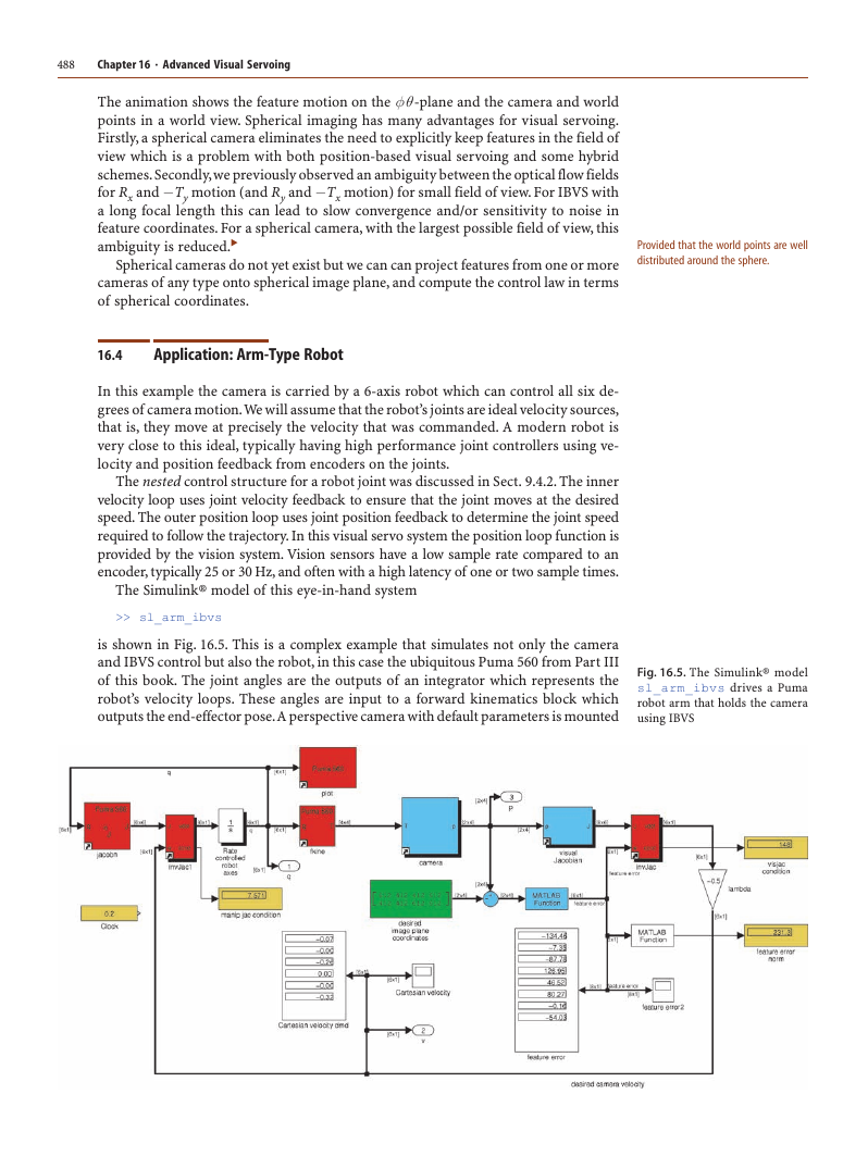
The Simulink® model of this eye-in-hand system
>> sl_arm_ibvs
Provided that the world points are well
distributed around the sphere.
is shown in Fig. 16.5. This is a complex example that simulates not only the camera
and IBVS control but also the robot, in this case the ubiquitous Puma 560 from Part III
of this book. The joint angles are the outputs of an integrator which represents the
robot’s velocity loops. These angles are input to a forward kinematics block which
outputs the end-effector pose. A perspective camera with default parameters is mounted
Fig. 16.5. The Simulink® model
sl_arm_ibvs drives a Puma
robot arm that holds the camera
using IBVS
�




 2023年江西萍乡中考道德与法治真题及答案.doc
 2012年重庆南川中考生物真题及答案.doc
 2013年江西师范大学地理学综合及文艺理论基础考研真题.doc
 2020年四川甘孜小升初语文真题及答案I卷.doc
 2020年注册岩土工程师专业基础考试真题及答案.doc
 2023-2024学年福建省厦门市九年级上学期数学月考试题及答案.doc
 2021-2022学年辽宁省沈阳市大东区九年级上学期语文期末试题及答案.doc
 2022-2023学年北京东城区初三第一学期物理期末试卷及答案.doc
 2018上半年江西教师资格初中地理学科知识与教学能力真题及答案.doc
 2012年河北国家公务员申论考试真题及答案-省级.doc
 2020-2021学年江苏省扬州市江都区邵樊片九年级上学期数学第一次质量检测试题及答案.doc
 2022下半年黑龙江教师资格证中学综合素质真题及答案.doc