NASA MARSHALL SPACE FLIGHT CENTER
Simulink Code Generation
Tutorial for generating C code from Simulink
Models using Simulink Coder
José Carlos Molina Fraticelli
4/25/2012
https://ntrs.nasa.gov/search.jsp?R=20120014980 2017-11-29T02:11:50+00:00Z�
1.
2. Good Programming Practices in Simulink .............................................................................. 4
3. Choosing Variable Data Types ................................................................................................ 6
Introduction ............................................................................................................................. 3
Contents
4. Hardware Implementation data type information .................................................................... 7
5. Naming Standards.................................................................................................................... 7
6. Creation of practice model for code generation ...................................................................... 8
7. Preparing practice model for code generation ....................................................................... 17
8. Compiling and Executing generated code ............................................................................. 29
9. Comparing output of MATLAB with that of the generated code ......................................... 36
References ..................................................................................................................................... 37
Appendix A Hardware Implementation Table .............................................................................. 38
�
1. Introduction
This document explains all the necessary steps in order to generate optimized C code from
Simulink (Ref. [2]) Models. This document also covers some general information on good
programming practices, selection of variable types, how to organize models and subsystems, and
finally how to test the generated C code and compare it with data from MATLAB (Ref. [1]).
(NOTE: This guide was prepared using MATLAB/Simulink Ver. R2011b (Ref. [1]).)
�
2. Good Programming Practices in Simulink
Below are some guidelines to follow when creating Simulink (Ref. [2]) Models:
Create bus objects for subsystems with many outputs and inputs. It makes organizing a
model simpler by requiring less cabling and also makes management of the data
contained in the bus easier when debugging as errors usually show up in a single location.
Avoid using Mux blocks to create Bus signals. Always use a Bus Creator blocks.
Avoid Crossing Cables when possible: There are a variety of ways to avoid crossing
cables which can make debugging Simulink (Ref. [2]) models complicated. Some of
these include: Organizing Subsystem Inputs to match cabling going into the subsystem,
Goto and From blocks, Bus Creator blocks, Bus Selector blocks, among others.
Determine variable types ahead of time. Simulink (Ref. [2]) defaults all data types to 64-
bit doubles by default. This can sometimes be a problem for code generation as not all
targets can support these types of variables and it can be hard to change these once a
model is created. This will save a lot of time trying to find problematic typecasts.
Use MATLAB (Ref. [1]) structures when working with Bus Signals.
Determine whether a model is a sub-function or a subsystem.
Avoid Algebraic Loops. They are problematic for code generation as stated by
Mathworks. If the algebraic loop cannot be avoided use a Unit Delay Block to break up
the loop. (NOTE: Verify that adding this block has not changed the output of the model.)
Avoid using different sampling times between models. This is not supported by code
generation.
Avoid using variable-step solvers. The only valid solver for code generation is the Fixed
Step Solver with a discrete time step.
Build models from the ground up with code generation in mind.
Test models as a standalone piece both in simulation and in the generated code and
ensure it is working before adding additional models.
Avoid using equal names for buses, data, constants and models. This can cause serious
problems with code generation. Use a naming standard to clearly define what every
object is or isn’t.
Rename models such as “Foo One Model”; to Foo_One_Model. This will help avoid
problems with code generation.
�
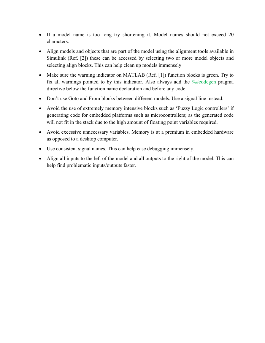
If a model name is too long try shortening it. Model names should not exceed 20
characters.
Align models and objects that are part of the model using the alignment tools available in
Simulink (Ref. [2]) these can be accessed by selecting two or more model objects and
selecting align blocks. This can help clean up models immensely
Make sure the warning indicator on MATLAB (Ref. [1]) function blocks is green. Try to
fix all warnings pointed to by this indicator. Also always add the %#codegen pragma
directive below the function name declaration and before any code.
Don’t use Goto and From blocks between different models. Use a signal line instead.
Avoid the use of extremely memory intensive blocks such as ‘Fuzzy Logic controllers’ if
generating code for embedded platforms such as microcontrollers; as the generated code
will not fit in the stack due to the high amount of floating point variables required.
Avoid excessive unnecessary variables. Memory is at a premium in embedded hardware
as opposed to a desktop computer.
Use consistent signal names. This can help ease debugging immensely.
Align all inputs to the left of the model and all outputs to the right of the model. This can
help find problematic inputs/outputs faster.
�
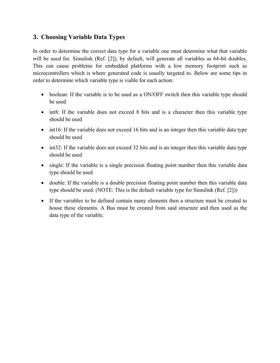
3. Choosing Variable Data Types
In order to determine the correct data type for a variable one must determine what that variable
will be used for. Simulink (Ref. [2]), by default, will generate all variables as 64-bit doubles.
This can cause problems for embedded platforms with a low memory footprint such as
microcontrollers which is where generated code is usually targeted to. Below are some tips in
order to determine which variable type is viable for each action:
boolean: If the variable is to be used as a ON/OFF switch then this variable type should
be used
int8: If the variable does not exceed 8 bits and is a character then this variable type
should be used
int16: If the variable does not exceed 16 bits and is an integer then this variable data type
should be used
int32: If the variable does not exceed 32 bits and is an integer then this variable data type
should be used
single: If the variable is a single precision floating point number then this variable data
type should be used
double: If the variable is a double precision floating point number then this variable data
type should be used. (NOTE: This is the default variable type for Simulink (Ref. [2]))
If the variables to be defined contain many elements then a structure must be created to
house these elements. A Bus must be created from said structure and then used as the
data type of the variable.
�
4. Hardware Implementation data type information
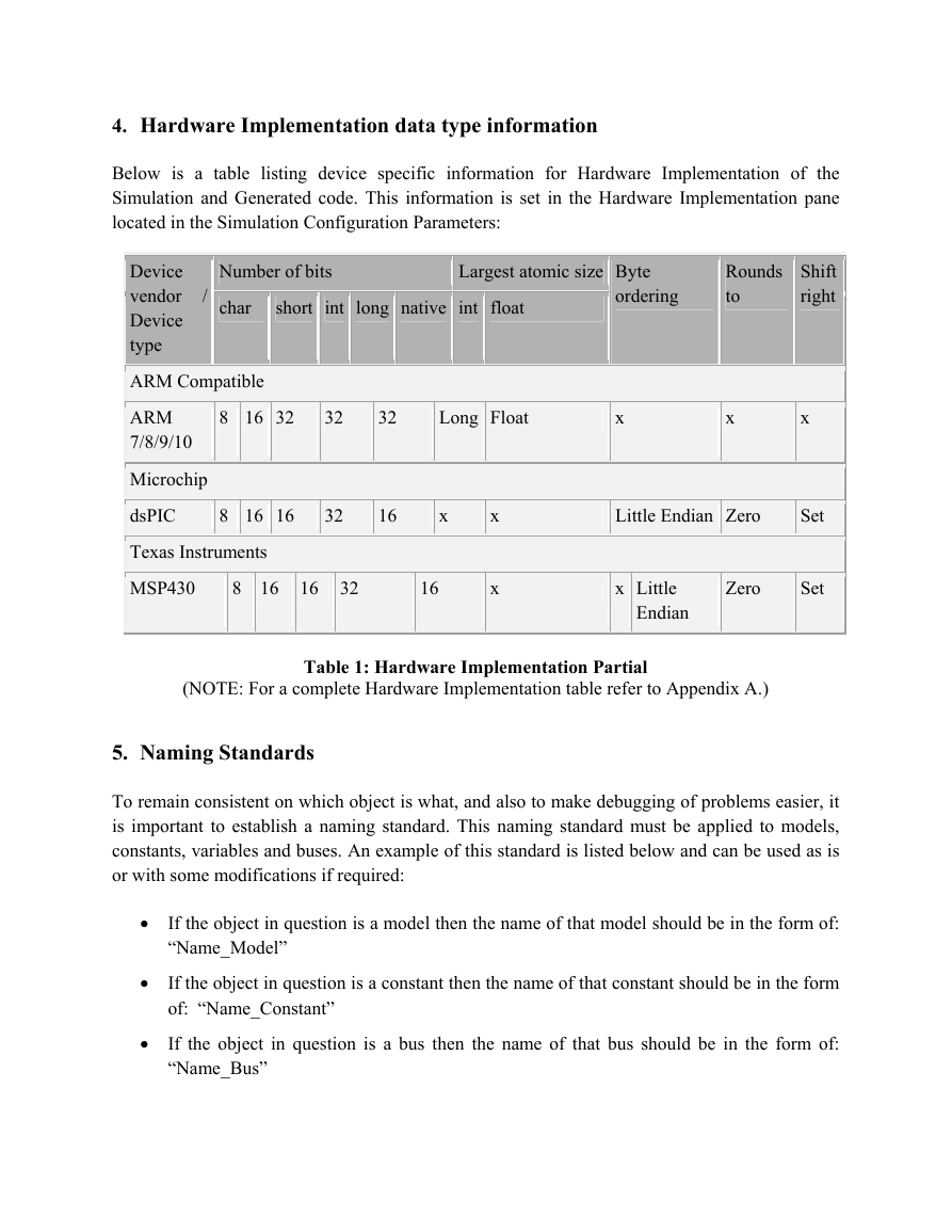
Below is a table listing device specific information for Hardware Implementation of the
Simulation and Generated code. This information is set in the Hardware Implementation pane
located in the Simulation Configuration Parameters:
Number of bits
char
short int long native int float
Largest atomic size Byte
ordering
Rounds
to
Shift
right
8 16 32
32
32
Long Float
x
x
x
/
Device
vendor
Device
type
ARM Compatible
ARM
7/8/9/10
Microchip
dsPIC
Texas Instruments
MSP430
8 16 16
32
16
x
8 16 16 32
16
x
x
Little Endian Zero
Set
x Little
Endian
Zero
Set
Table 1: Hardware Implementation Partial
(NOTE: For a complete Hardware Implementation table refer to Appendix A.)
5. Naming Standards
To remain consistent on which object is what, and also to make debugging of problems easier, it
is important to establish a naming standard. This naming standard must be applied to models,
constants, variables and buses. An example of this standard is listed below and can be used as is
or with some modifications if required:
If the object in question is a model then the name of that model should be in the form of:
“Name_Model”
If the object in question is a constant then the name of that constant should be in the form
of: “Name_Constant”
If the object in question is a bus then the name of that bus should be in the form of:
“Name_Bus”
�
If the object in question is a signal then the name of that signal should be in the form of:
“Name_Signal”
If the object in question is a function then the name of that signal should be in the form
of: “Name_Func”
If the object in question is a subsystem input then the name of that input should be in the
form of: "Name_Input"
If the object in question is a subsystem input then the name of that input should be in the
form of: "Name_Output"
6. Creation of practice model for code generation
In this section a new practice model will be created in order to demonstrate the necessary steps to
do successful code generation from any Simulink (Ref. [2]) model.
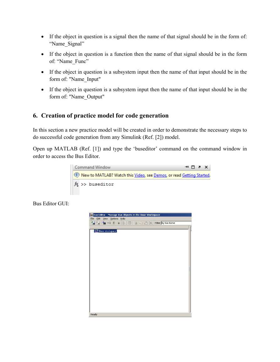
Open up MATLAB (Ref. [1]) and type the ‘buseditor’ command on the command window in
order to access the Bus Editor.
Bus Editor GUI:
�


 2023年江西萍乡中考道德与法治真题及答案.doc
 2012年重庆南川中考生物真题及答案.doc
 2013年江西师范大学地理学综合及文艺理论基础考研真题.doc
 2020年四川甘孜小升初语文真题及答案I卷.doc
 2020年注册岩土工程师专业基础考试真题及答案.doc
 2023-2024学年福建省厦门市九年级上学期数学月考试题及答案.doc
 2021-2022学年辽宁省沈阳市大东区九年级上学期语文期末试题及答案.doc
 2022-2023学年北京东城区初三第一学期物理期末试卷及答案.doc
 2018上半年江西教师资格初中地理学科知识与教学能力真题及答案.doc
 2012年河北国家公务员申论考试真题及答案-省级.doc
 2020-2021学年江苏省扬州市江都区邵樊片九年级上学期数学第一次质量检测试题及答案.doc
 2022下半年黑龙江教师资格证中学综合素质真题及答案.doc