logo资料库

QCA7000使用说明手册.pdf

第1页 / 共308页
第2页 / 共308页
第3页 / 共308页
第4页 / 共308页
第5页 / 共308页
第6页 / 共308页
第7页 / 共308页
第8页 / 共308页
资料共308页,剩余部分请下载后查看
Functionality Supported:
1 Architecture Overview
1.1 Powerline Frequency
1.2 Device Components
1.3 Design Considerations
1.4 Differences between the Ethernet/MII and SPI Slave Host Interfaces
1.5 Supported Flash Devices
2 NVM File Formats
2.1 Data Structures
2.1.1 NVM Chain
2.1.2 NVM Header
2.1.3 Modules
2.1.4 NVM Chain Manifest
2.1.5 NVM Chain Traversal
2.1.6 Checksum Calculation
3 Boot Process
3.1 Boot from Flash
3.2 Device Identification
3.3 Boot from Host
3.3.1 Extracting Modules from Firmware NVM Chain
3.3.2 Boot from Host Procedure
3.4 Major Boot Loader changes Compared to Previous Chips
3.5 Caveats
3.6 Initial Provisioning using AVitar
3.6.1 Installation and Start the AVitar Application
3.6.2 Initial Provisioning of Blank Flash Devices
3.6.2.1 Booting Firmware from Host
3.6.2.2 Writing Firmware and PIB into NVM
3.6.2.3 Dual Firmware in Flash
3.7 Module Operations
3.7.1 Overview
3.7.2 Updating the PIB
3.7.2.1 Merge
3.7.2.2 Replace (with Personalization)
3.7.2.3 Replace (Unconditional)
3.7.3 Module Operations for Reading Module Content
3.7.3.1 PIB Read
3.7.4 Module Operations for Flashless Devices (No NVM)
3.7.4.1 Major Changes from Previous Design
3.7.4.2 Powerline PIB-Only Update
3.7.4.2.1 Successful Powerline PIB Only Update
3.7.4.2.2 Error Cases
3.7.4.3 Powerline PIB and Firmware Update
3.7.4.4 PIB Merge Operation via Embedded Host
3.7.4.4.1 Successful PIB Merge Process
3.7.4.4.2 Error Cases
3.7.5 Module Operations for Devices with Flash (NVM)
3.7.5.1 Firmware and PIB Update for Devices with NVM
3.7.5.2 PIB Only Update for Devices with NVM
3.7.5.3 Production Test System Firmware and PIB Update
3.7.5.4 Initial Provisioning
3.8 Major Changes to Firmware and PIB update Compared to Previous Chips
3.9 Flash Layout
4 PIB Upgrade
4.1 PIB Overview
4.2 Factory Default PIB
4.3 User PIB
4.3.1 Manufacturing
4.3.2 Deployment
4.3.3 Field Upgrade
4.3.4 End-user Settings
5 Encryption
5.1 Device Access Key (DAK)
5.2 Device Password (DPW)
5.3 Network Membership Key (NMK)
5.4 Network Password (NPW)
5.5 Password Hashing
6 Pushbutton Simple Connect
6.1 Introduction
6.2 Logical Networks
6.3 Considerations
6.4 Joining a Network
6.5 Leaving a Network
6.6 Visual Feedback
6.7 Variable Time Limits
6.8 The Ground Rules
6.9 Push Button Timing Customization
6.10 Case 1: Forming a Network
6.11 Case 2: Joining a Network
6.12 Case 3: Leaving a Network
6.13 Case 4: Join Multiple Devices to a Network
6.14 Default Power LED Behavior
7 GPIO/LED Engine
7.1 Introduction
7.1.1 Programmability for Customization
7.2 Programming Restriction on GPIOs
7.3 Push Button Programmability
7.3.1 Simple Connect Function
7.3.2 Reset to Factory Defaults
7.3.3 NMK Randomization
7.3.4 Report GPIO State Change
7.3.5 Request Remote GPIO State Change
7.4 Standby Mode Interaction with Push Button and Connection Quality Diagnostics
7.5 LED Programmability
7.5.1 Multiple Software Events on one LED Behavior
7.5.2 Software Event Definitions
7.5.3 Mapping between Events and LED Behaviors
7.5.4 Creating LED Behaviors
7.6 Power Saving Options
8 TEI, NID & SNID
8.1 Terminal Equipment Identifier (TEI)
8.2 Network Identifier (NID)
8.3 Short Network Identifier (SNID)
9 Bridging
9.1 Acting as an AV Bridge
9.1.1 Behavior for Incoming Traffic from the Powerline Network
9.1.2 Behavior for Incoming Traffic from the Bridged Network
9.2 Communicating through an AV Bridge
9.2.1 Communication with a Known DA
9.2.1.1 Known AV Station
9.2.1.2 Known Bridged Destination
9.2.1.3 Known Multicast Address
9.2.1.4 Unknown Unicast Destination
9.2.1.5 Broadcast Address
9.2.1.6 Unknown Multicast Address
9.3 MAC Address Aging
10 Multiport Switch (AR7420 Only)
11 Generic Multi-Port Ethernet Switch Controller Support (AR7420 Only)
11.1 MDIO Command MME
11.2 Module Operations MME
12 Internal Switch Programming (AR7420 Only)
12.1 PIB Base Switch Configuration
12.1.1 PIB Offsets
13 Quality of Service (QoS)
13.1 Introduction
13.2 QoS Capabilities
13.3 Classification
13.4 VLAN, TOS Priority
13.4.1 VLAN ID
13.4.2 Source/Destination MAC Address
13.4.3 TCP/UDP Port Number
13.4.4 IPv4 Source and Destination Port
13.4.5 IPv6 Flow Label
13.4.6 Default Classification
13.5 Priority Based Queuing
13.6 TTL
13.7 Aggregation
13.8 Priority Contention
13.9 Configuration
13.9.1 TCP/UDP Port Number
13.9.2 MAC Address
13.9.3 VLAN CoS Bits
13.9.4 TOS Priority Bits
13.9.5 How to Modify Default Classification
13.9.6 TTL
13.9.7 Classification Setting MME
13.9.7.1 Special Consideration on storage of the Classification Rule Sets
13.9.7.1.1 Storage of Classification Rules Sets in current runtime DRAM (Volatile)
13.9.7.1.2 Storage of Classification Rule Sets Non-Volatile RAM (PIB)
13.9.7.2 Special Consideration on use of the Classification Rules
13.9.7.2.1 Overview of Use of Classification by the PLC chipset
13.9.7.2.2 Organization of Classification Rule Sets
13.10 Scenario Examples
13.10.1 Performance Testing
13.10.2 Residential Gateway
13.10.3 MDU Internet Distribution
13.10.4 Downstream IPTV with MDU Upstream Traffic
13.11 PLC Multimedia QoS (AR7420 Only)
13.12 Testing
14 UART Transparent (QCA7000 Only)
15 UART Transparent Mode Multipoint (QCA7000 Only)
16 IGMP and MLD Multicast Snooping
16.1 How Snooping Works
16.1.1 Internet Engineering Task Force (IETF)
16.2 Qualcomm Atheros IGMP Implementation
16.3 IGMP Topology Enhancements for Improved Microsoft© IPTV Delivery
17 Advanced Power Management
17.1 Options
17.1.1 Uncoordinated Sleep Selection Option
17.1.2 Coordinated Sleep Selection Option (QCA7000 Only)
17.2 Events
18 Dynamic PSD
19 HomePlug Generic MMEs
19.1 Management Message Byte Order
19.1.1 Original Destination Address (ODA)
19.1.2 Original Source Address (OSA)
19.2 VLAN Tag
19.3 MTYPE
19.4 Management Message Version (MMV)
19.5 Management Message Type (MMTYPE)
19.5.1 Fragment Management Information
19.6 Management Message Entry Data (MME)
19.7 MME PAD
19.8 Station – Central Coordination (CCo) MMEs
19.8.1 CC_DISCOVER_LIST.REQ
19.8.2 CC_DISCOVER_LIST.CNF
19.8.3 CC_WHO_RU.REQ
19.8.4 CC_WHO_RU.CNF
19.9 Station – Station
19.9.1 CM_ENCRYPTED_PAYLOAD.IND
19.9.1.1 Payload Encryption Key Select (PEKS)
19.9.1.2 AVLN Status
19.9.1.3 Protocol ID (PID)
19.9.1.4 Protocol Run Number (PRN)
19.9.1.5 Protocol Message Number (PMN)
19.9.1.6 Initialization Vector (IV) or Universally Unique Identifier (UUID)
19.9.1.7 Length (Len)
19.9.1.8 Random Filler (RF)
19.9.1.9 Management Message (MM) or HLE Payload
19.9.1.10 Cyclic Redundancy Check (CRC)
19.9.1.11 Protocol ID (PID - Encrypted)
19.9.1.12 Protocol Run Number (PRN - Encrypted)
19.9.1.13 Protocol Message Number (PMN - Encrypted)
19.9.1.14 Padding - Encrypted
19.9.1.15 RF Length (RFLen - Encrypted)
19.9.2 CM_ENCRYPTED_PAYLOAD.RSP
19.9.2.1 Result
19.9.3 CM_SET_KEY.REQ
19.9.3.1 Key Type
19.9.3.2 NID
19.9.3.3 New_EKS
19.9.4 CM_SET_KEY.CNF
19.9.5 CM_GET_KEY.REQ
19.9.5.1 Request Type
19.9.5.2 Requested Key Type
19.9.5.3 NID
19.9.6 CM_GET_KEY.CNF
19.9.6.1 Request Type
19.9.6.2 Requested Key Type
19.9.7 CM_BRG_INFO.REQ
19.9.8 CM_BRG_INFO.CNF
19.9.8.1 Bridge TEI (BTEI)
19.9.8.2 Number of Bridge Destination Addresses (NBDA)
19.9.8.3 Bridged Destination Address [i] (BDA[i])
19.9.9 CM_STA_CAP.REQ
19.9.10 CM_STA_CAP.CNF
19.9.11 CM_NW_INFO.REQ
19.9.12 CM_NW_INFO.CNF
19.9.13 CM_NW_STATS.REQ
19.9.14 CM_NW_STATS.CNF
19.9.15 CM_HFID.REQ
19.9.16 CM_HFID_CNF
19.9.17 CM_MME_ERROR.IND
19.10 Green PHY SLAC Protocol
19.10.1 Signal Level Attenuation Characterization
19.10.2 CM_STA_IDENTIFY.REQ
19.10.3 CM_STA_IDENTIFY.CNF
19.10.4 CM_SLAC_PARM.REQ
19.10.4.1 APPLICATION TYPE
19.10.4.2 SECURITY TYPE
19.10.4.3 RUN IDENTIFIER
19.10.4.4 CIPHER SUITE SET SIZE
19.10.4.5 CIPHER SUITE [1] to CIPHER SUITE [N]
19.10.5 CM_SLAC_PARM.CNF
19.10.5.1 M-SOUND_TARGET
19.10.5.2 NUM_SOUNDS
19.10.5.3 Time_Out
19.10.5.4 RESP_TYPE
19.10.5.5 FORWARDING_STA
19.10.5.6 APPLICATION TYPE
19.10.5.7 SECURITY TYPE
19.10.5.8 RUN IDENTIFIER
19.10.5.9 CIPHER SUITE
19.10.6 CM_START_ATTEN_CHAR.IND
19.10.6.1 APPLICATION TYPE
19.10.6.2 SECURITY TYPE
19.10.6.3 ACVarField
19.10.6.4 NUM_SOUNDS
19.10.6.5 Time_Out
19.10.6.6 RESP_TYPE
19.10.6.7 FORWARDING_STA
19.10.6.8 RUN IDENTIFIER
19.10.7 CM_ATTEN_CHAR.IND
19.10.7.1 APPLICATION TYPE
19.10.7.2 SECURITY TYPE
19.10.7.3 ACVarField
19.10.7.4 SOURCE_ADDRESS
19.10.7.5 RUN IDENTIFIER
19.10.7.6 SOURCE IDENTIFIER
19.10.7.7 RESPONDER IDENTIFIER
19.10.7.8 NumSounds
19.10.7.9 ATTEN_PROFILE
19.10.8 CM_ATTEN_CHAR.RSP
19.10.8.1 APPLICATION TYPE
19.10.8.2 SECURITY TYPE
19.10.8.3 ACVarField
19.10.8.4 SOURCE_ADDRESS
19.10.8.5 RUN IDENTIFIER
19.10.8.6 SOURCE IDENTIFIER
19.10.8.7 RESPONDER IDENTIFIER
19.10.9 CM_PKCS_CERT.REQ
19.10.10 CM_PKCS_CERT.CNF
19.10.11 CM_PKCS_CERT.IND
19.10.12 CM_PKCS_CERT.RSP
19.10.13 CM_MNBC_SOUND.IND
19.10.13.1 APPLICATION TYPE
19.10.13.2 SECURITY TYPE
19.10.13.3 MSVarField
19.10.13.4 SENDER IDENTIFIER
19.10.13.5 CNT
19.10.13.6 RUN IDENTIFIER
19.10.13.7 RND
19.10.14 CM_VALIDATE.REQ
19.10.15 CM_VALIDATE.CNF
19.10.16 CM_SLAC_MATCH.REQ
19.10.16.1 APPLICATION TYPE
19.10.16.2 SECURITY TYPE
19.10.16.3 MVFLength
19.10.16.4 Match Variable Field
19.10.17 CM_SLAC_MATCH.CNF
19.10.17.1 APPLICATION TYPE
19.10.17.2 SECURITY TYPE
19.10.17.3 MVFLength
19.10.17.4 Match Variable Field
19.10.18 CM_SLAC_USER_DATA.REQ
19.10.18.1 Broadcast_TLV
19.10.18.2 User_data_TLVs
19.10.18.2.1 TLV
19.10.18.2.2 TLV_TYPE
19.10.18.2.3 TLV_STR_LEN
19.10.18.2.4 TLV_INFO_STR
19.10.18.2.4.1 OUI
19.10.18.2.4.2 Subtype
19.10.18.2.4.3 INFO_STR
19.10.19 CM_ATTEN_PROFILE.IND (GREEN PHY)
19.11 PEV - EVSE Association
19.11.1 PEV – EVSE Association Procedure
19.11.1.1 Configuration of GP stations in PEV and EVSE
19.11.1.2 SLAC
19.11.1.2.1 PEV SLAC
19.11.1.2.2 EVSE SLAC
19.11.1.3 Matching Decision at PEV
19.11.1.4 Validation
19.11.1.5 Inform EVSE of Decision
19.11.1.6 Matching Confirm by EVSE
19.11.1.7 Network Join
19.11.1.8 Amplitude Map exchange
19.11.2 Secure SLAC Overview
19.11.2.1 Public Key Certificates
19.11.3 Exchange of User Data
19.11.4 EVSE Power Save Restrictions
20 Qualcomm Atheros Manufacturer Specific MMEs
20.1 Manufacturer Specific MME Header Format
20.2 Start Push Button Encryption MME (MS_PB_ENC)
21 Qualcomm Atheros Vendor Specific MMEs
21.1 Vendor Specific MMEs Header Format
21.2 Get Device/SW Version MME (VS_SW_VER)
21.2.1 Get Device/SW Version Details/Examples
21.2.1.1 Get Device/SW Version – Expected Return Values for Production ICs
21.3 Get NVM Parameters MME (VS_GET_NVM)
21.4 Reset Device MME (VS_RS_DEV)
21.5 Get Watchdog Report MME (VS_WD_RPT)
21.6 Link Statistics MME (VS_LNK_STATS)
21.7 Network Info MME (VS_NW_INFO)
21.8 Check Points MME (VS_CP_RPT)
21.9 Set Encryption Key Request MME (VS_SET_KEY)
21.10 Get Manufacturer String MME (VS_MFG_STRING)
21.11 Embedded Host Action Requested MME (VS_HST_ACTION)
21.12 Get Device Attributes MME (VS_OP_ATTRIBUTES)
21.13 Ethernet PHY Settings (VS_ENET_SETTINGS)
21.14 Tone Map Characteristics MME (VS_TONE_MAP_CHAR)
21.15 Network Information & Statistics MME (VS_NW_INFO_STATS)
21.16 Reset to Factory Defaults MME (VS_FAC_DEFAULTS)
21.17 Multicast Group Info MME (VS_MULTICAST_INFO)
21.18 Classification Setting MME (VS_CLASSIFICATION)
21.19 Receive Tone Map Characteristics MME (VS_RX_TONE_MAP_CHAR)
21.20 Set LED Behaviors MME (VS_SET_LED_BEHAVIOR)
21.21 Write and Execute Applet MME (VS_WRITE_AND_EXECUTE_APPLET)
21.22 Read or Write MDIO Settings (VS_MDIO_COMMAND)
21.23 Static Neighbor Network Mitigation Operation MME (VS_NN_MITIGATE)
21.24 Module Operation MME (VS_MODULE_OPERATION)
21.25 Diagnostic Network Probe MME (VS_DIAG_NETWORK_PROBE)
21.26 Powerline Link Status MME (VS_PL_LNK_STATUS)
21.27 GPIO State Change MME (VS_GPIO_STATE_CHANGE)
21.28 Multi-Port Link Status MME (VS_MULTIPORT_LNK_STA)
21.29 Standby MME (VS_STANDBY)
21.30 Sleep Schedule MME (VS_SLEEPSCHEDULE)
21.31 Sleep Schedule Notification MME (VS_SLEEPSCHEDULE_NOTIFICATION)
21.32 Microcontroller Diagnostics MME (VS_MICROCONTROLLER_DIAG)
21.33 Get Property MME (VS_GET_PROPERTY)
21.34 Set Property MME (VS_SET_PROPERTY)
21.35 Attenuation Characteristics MME (VS_ATTEN_CHAR)
22 QCA7000 SPI Device Driver
22.1 SPI Frame Encapsulation
22.2 SPI Requirements
22.3 SPI Transfers
22.4 Legacy vs. Burst Transfer Modes
22.5 Write Buffer Sequence
22.5.1 Register List and Control Bits
22.5.2 Reading an QCA7000 Register over SPI
22.5.3 Writing an QCA7000 Register over SPI
22.5.4 Writing a Packet over SPI
22.6 How is a SPI Frame Constructed?
22.7 Basic Network Driver Operations for QCA7000 SPI Interface
22.8 Handling the QCA7000 Interrupt
22.9 Consider Enabling All Interrupts
22.10 Handling Initialization
22.11 Transmit Considerations
22.12 Receive Considerations
22.13 Known QCA7000 Differences from the PL14
23 QCA7000 UART Interface
23.1 UART Frame Encapsulation
23.2 UART Requirements
23.3 UART Driver Architecture
24 Building a Virtual Machine for the PL16
24.1 Why a Virtual Machine?
24.2 Download VMware Player
24.3 Download Ubuntu 10.10 LTS
24.4 Install WMware Player™
24.5 Install Ubuntu on VMware Player
24.5.1 Create New Virtual Machine
24.5.2 Enter Ubuntu Username and Password
24.5.3 Name the Virtual Machine and Location
24.5.4 Specify Virtual Disk Capacity
24.5.5 Customize Hardware
24.5.6 Ignore Warning Message
24.5.7 Login to Ubuntu
24.6 Share Host File Folders
24.7 Connect to the Network
24.8 Install Extra Ubuntu Packages
24.9 What’s Next?
25 Program the PL16 Device using Binaries
25.1 Obtain QCA PL16 Binary Archive
25.2 Extract the Binary Archive
25.3 Write Bootable Image
26 Compile PL16 Software from Source
26.1 Download Freescale Board Support Package
26.2 Obtain QCA Archives and Script Files
26.3 Copy Board Support Packages to Home Folder
26.4 Enable Special Permissions
26.5 Extract the Freescale Board Support Package
26.6 Install Freescale LTIB
26.7 Install Freescale Scripts
26.8 Build Freescale Image
26.8.1 Select Freescale iMX Platform Series
26.8.2 Select iMX28 Software Stack
26.8.3 Select Freescale i.MX28 Platform
26.8.4 Configure iMX28 Board Settings
26.8.5 Build LTIB Packages
26.9 Install QCA Source Package
26.10 Write Bootable Image
26.10.1 Ubuntu 11.10
27 QCA Installation Scripts
27.1 Environment
27.2 QCA-PL16-extra.sh
27.3 QCA-PL16-setup.sh
27.4 QCA-PL16-patch.sh
28 Overview of PL16 Software
28.1 Software Boot Sequence
28.2 File System Layout
28.3 PL16 Configuration
28.3.1 SPI Driver
28.3.1.1 Resource Requirements
28.3.2 UART Driver
28.3.2.1 Resource Requirements
29 PIB API
29.1 Namespace
29.2 Programming Guidelines
29.3 Getters and Setters Functions
AR7420, QCA6410 IEEE 1901, HomePlug® AV and QCA7000 HomePlug® Green PHY Powerline (PLC) Chipset Programmer’s Guide 80-Y1908-1 Rev. H August 12, 2013 Q ualco m m Atheros Confidential NO PUBLIC DISCLOSURE PERMITTED: Please report postings of this document on public servers or websites to: DocCtrlAgent@qualcomm.com. Restricted Distribution: Not to be distributed to anyone who is not an employee of either Qualcomm or its subsidiaries without the express approval of Qualcomm's Configuration Management. Not to be used, copied, reproduced, or modified in whole or in part, nor its contents revealed in any manner to others without the express written permission of Qualcomm Atheros, Inc. Qualcomm is a registered trademark of QUALCOMM Incorporated. Atheros is a registered trademark of Qualcomm Atheros, Inc. All other registered and unregistered trademarks are the property of QUALCOMM Incorporated, Qualcomm Atheros, Inc., or their respective owners and used with permission. Registered marks owned by QUALCOMM Incorporated and Qualcomm Atheros, Inc. are registered in the United States and may be registered in other countries. This technical data may be subject to U.S. and international export, re-export, or transfer (“export”) laws. Diversion contrary to U.S. and international law is strictly prohibited. Confidential and Proprietary – Qualcomm Atheros, Inc. Qualcomm Atheros, Inc. 1700 Technology Drive San Jose, CA 95110 U.S.A. © 2012-2013 Qualcomm Atheros, Inc.
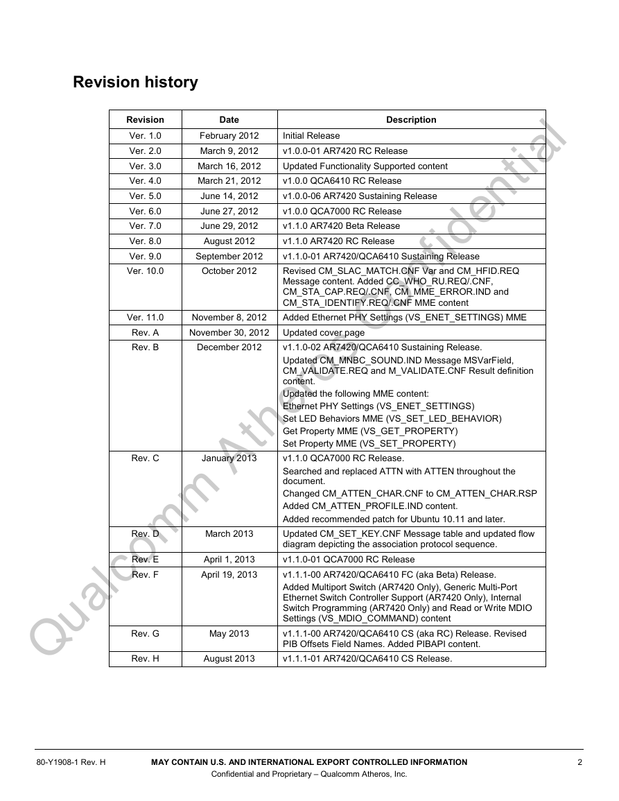
Revision history Date Description September 2012 October 2012 November 8, 2012 November 30, 2012 Updated cover page Revision Ver. 1.0 Ver. 2.0 Ver. 3.0 Ver. 4.0 Ver. 5.0 Ver. 6.0 Ver. 7.0 Ver. 8.0 Ver. 9.0 Ver. 10.0 February 2012 March 9, 2012 March 16, 2012 March 21, 2012 June 14, 2012 June 27, 2012 June 29, 2012 August 2012 Initial Release v1.0.0-01 AR7420 RC Release Updated Functionality Supported content v1.0.0 QCA6410 RC Release v1.0.0-06 AR7420 Sustaining Release v1.0.0 QCA7000 RC Release v1.1.0 AR7420 Beta Release v1.1.0 AR7420 RC Release v1.1.0-01 AR7420/QCA6410 Sustaining Release Revised CM_SLAC_MATCH.CNF Var and CM_HFID.REQ Message content. Added CC_WHO_RU.REQ/.CNF, CM_STA_CAP.REQ/.CNF, CM_MME_ERROR.IND and CM_STA_IDENTIFY.REQ/.CNF MME content Added Ethernet PHY Settings (VS_ENET_SETTINGS) MME Q ualco m m Atheros Confidential v1.1.0-02 AR7420/QCA6410 Sustaining Release. Updated CM_MNBC_SOUND.IND Message MSVarField, CM_VALIDATE.REQ and M_VALIDATE.CNF Result definition content. Updated the following MME content: Ethernet PHY Settings (VS_ENET_SETTINGS) Set LED Behaviors MME (VS_SET_LED_BEHAVIOR) Get Property MME (VS_GET_PROPERTY) Set Property MME (VS_SET_PROPERTY) v1.1.0 QCA7000 RC Release. Searched and replaced ATTN with ATTEN throughout the document. Changed CM_ATTEN_CHAR.CNF to CM_ATTEN_CHAR.RSP Added CM_ATTEN_PROFILE.IND content. Added recommended patch for Ubuntu 10.11 and later. Updated CM_SET_KEY.CNF Message table and updated flow diagram depicting the association protocol sequence. v1.1.0-01 QCA7000 RC Release v1.1.1-00 AR7420/QCA6410 FC (aka Beta) Release. Added Multiport Switch (AR7420 Only), Generic Multi-Port Ethernet Switch Controller Support (AR7420 Only), Internal Switch Programming (AR7420 Only) and Read or Write MDIO Settings (VS_MDIO_COMMAND) content v1.1.1-00 AR7420/QCA6410 CS (aka RC) Release. Revised PIB Offsets Field Names. Added PIBAPI content. v1.1.1-01 AR7420/QCA6410 CS Release. May 2013 August 2013 March 2013 April 1, 2013 April 19, 2013 Rev. D Rev. E Rev. F Rev. G Rev. H Ver. 11.0 Rev. A Rev. B December 2012 Rev. C January 2013 80-Y1908-1 Rev. H MAY CONTAIN U.S. AND INTERNATIONAL EXPORT CONTROLLED INFORMATION 2 Confidential and Proprietary – Qualcomm Atheros, Inc.
Contents Q ualco m m Atheros Confidential Functionality Supported: ................................................................................. 17 1 Architecture Overview .................................................................................. 19 1.1 Powerline Frequency .................................................................................................. 19 1.2 Device Components .................................................................................................... 19 1.3 Design Considerations ................................................................................................ 19 1.4 Differences between the Ethernet/MII and SPI Slave Host Interfaces ....................... 20 1.5 Supported Flash Devices............................................................................................. 21 2 NVM File Formats .......................................................................................... 22 2.1 Data Structures ............................................................................................................ 22 2.1.1 NVM Chain ..................................................................................................... 22 2.1.2 NVM Header ................................................................................................... 23 2.1.3 Modules ........................................................................................................... 24 2.1.4 NVM Chain Manifest ...................................................................................... 24 2.1.5 NVM Chain Traversal ..................................................................................... 26 2.1.6 Checksum Calculation ..................................................................................... 26 3 Boot Process ................................................................................................. 28 3.1 Boot from Flash .......................................................................................................... 28 3.2 Device Identification ................................................................................................... 28 3.3 Boot from Host ........................................................................................................... 29 3.3.1 Extracting Modules from Firmware NVM Chain ............................................ 29 3.3.2 Boot from Host Procedure ............................................................................... 29 3.4 Major Boot Loader changes Compared to Previous Chips ......................................... 32 3.5 Caveats ........................................................................................................................ 32 3.6 Initial Provisioning using AVitar ................................................................................ 33 3.6.1 Installation and Start the AVitar Application .................................................. 33 3.6.2 Initial Provisioning of Blank Flash Devices .................................................... 33 3.7 Module Operations ..................................................................................................... 34 3.7.1 Overview ......................................................................................................... 34 3.7.2 Updating the PIB ............................................................................................. 36 3.7.3 Module Operations for Reading Module Content ........................................... 36 3.7.4 Module Operations for Flashless Devices (No NVM) .................................... 37 3.7.5 Module Operations for Devices with Flash (NVM) ........................................ 41 3.8 Major Changes to Firmware and PIB update Compared to Previous Chips ............... 44 3.9 Flash Layout ............................................................................................................... 45 4 PIB Upgrade ................................................................................................... 46 4.1 PIB Overview ............................................................................................................. 46 4.2 Factory Default PIB .................................................................................................... 46 80-Y1908-1 Rev. H MAY CONTAIN U.S. AND INTERNATIONAL EXPORT CONTROLLED INFORMATION 3 Confidential and Proprietary – Qualcomm Atheros, Inc.
AR7420, QCA6410 and QCA7000 PLC Chipset Programmer’s Guide Q ualco m m Atheros Confidential 4.3 User PIB ...................................................................................................................... 47 4.3.1 Manufacturing.................................................................................................. 47 4.3.2 Deployment...................................................................................................... 48 4.3.3 Field Upgrade .................................................................................................. 48 4.3.4 End-user Settings ............................................................................................. 48 5 Encryption ...................................................................................................... 49 5.1 Device Access Key (DAK) ......................................................................................... 49 5.2 Device Password (DPW) ............................................................................................ 49 5.3 Network Membership Key (NMK) ............................................................................. 50 5.4 Network Password (NPW) .......................................................................................... 50 5.5 Password Hashing ....................................................................................................... 50 6 Pushbutton Simple Connect ......................................................................... 52 6.1 Introduction ................................................................................................................. 52 6.2 Logical Networks ........................................................................................................ 52 6.3 Considerations ............................................................................................................ 52 6.4 Joining a Network ....................................................................................................... 53 6.5 Leaving a Network ...................................................................................................... 53 6.6 Visual Feedback .......................................................................................................... 53 6.7 Variable Time Limits .................................................................................................. 53 6.8 The Ground Rules ....................................................................................................... 53 6.9 Push Button Timing Customization ............................................................................ 54 6.10 Case 1: Forming a Network ...................................................................................... 54 6.11 Case 2: Joining a Network ........................................................................................ 55 6.12 Case 3: Leaving a Network ....................................................................................... 56 6.13 Case 4: Join Multiple Devices to a Network............................................................. 56 6.14 Default Power LED Behavior ................................................................................... 56 7 GPIO/LED Engine .......................................................................................... 58 7.1 Introduction ................................................................................................................. 58 7.1.1 Programmability for Customization ................................................................ 58 7.2 Programming Restriction on GPIOs ........................................................................... 58 7.3 Push Button Programmability ..................................................................................... 58 7.3.1 Simple Connect Function ................................................................................ 59 7.3.2 Reset to Factory Defaults ................................................................................. 59 7.3.3 NMK Randomization ....................................................................................... 59 7.3.4 Report GPIO State Change .............................................................................. 59 7.3.5 Request Remote GPIO State Change ............................................................... 59 7.4 Standby Mode Interaction with Push Button and Connection Quality Diagnostics ... 60 7.5 LED Programmability ................................................................................................. 60 7.5.1 Multiple Software Events on one LED Behavior ............................................ 61 7.5.2 Software Event Definitions .............................................................................. 61 7.5.3 Mapping between Events and LED Behaviors ................................................ 63 7.5.4 Creating LED Behaviors .................................................................................. 63 7.6 Power Saving Options ................................................................................................ 64 80-Y1908-1 Rev. H MAY CONTAIN U.S. AND INTERNATIONAL EXPORT CONTROLLED INFORMATION 4 Confidential and Proprietary – Qualcomm Atheros, Inc.
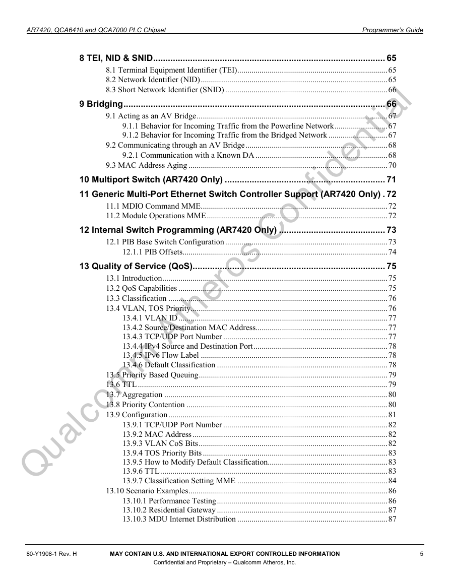
AR7420, QCA6410 and QCA7000 PLC Chipset Programmer’s Guide Q ualco m m Atheros Confidential 8 TEI, NID & SNID .............................................................................................. 65 8.1 Terminal Equipment Identifier (TEI) .......................................................................... 65 8.2 Network Identifier (NID) ............................................................................................ 65 8.3 Short Network Identifier (SNID) ................................................................................ 66 9 Bridging .......................................................................................................... 66 9.1 Acting as an AV Bridge .............................................................................................. 67 9.1.1 Behavior for Incoming Traffic from the Powerline Network .......................... 67 9.1.2 Behavior for Incoming Traffic from the Bridged Network ............................. 67 9.2 Communicating through an AV Bridge ...................................................................... 68 9.2.1 Communication with a Known DA ................................................................. 68 9.3 MAC Address Aging .................................................................................................. 70 10 Multiport Switch (AR7420 Only) ................................................................. 71 11 Generic Multi-Port Ethernet Switch Controller Support (AR7420 Only) . 72 11.1 MDIO Command MME ............................................................................................ 72 11.2 Module Operations MME ......................................................................................... 72 12 Internal Switch Programming (AR7420 Only) ........................................... 73 12.1 PIB Base Switch Configuration ................................................................................ 73 12.1.1 PIB Offsets..................................................................................................... 74 13 Quality of Service (QoS).............................................................................. 75 13.1 Introduction ............................................................................................................... 75 13.2 QoS Capabilities ....................................................................................................... 75 13.3 Classification ............................................................................................................ 76 13.4 VLAN, TOS Priority ................................................................................................. 76 13.4.1 VLAN ID ....................................................................................................... 77 13.4.2 Source/Destination MAC Address................................................................. 77 13.4.3 TCP/UDP Port Number ................................................................................. 77 13.4.4 IPv4 Source and Destination Port .................................................................. 78 13.4.5 IPv6 Flow Label ............................................................................................ 78 13.4.6 Default Classification .................................................................................... 78 13.5 Priority Based Queuing ............................................................................................. 79 13.6 TTL ........................................................................................................................... 79 13.7 Aggregation .............................................................................................................. 80 13.8 Priority Contention ................................................................................................... 80 13.9 Configuration ............................................................................................................ 81 13.9.1 TCP/UDP Port Number ................................................................................. 82 13.9.2 MAC Address ................................................................................................ 82 13.9.3 VLAN CoS Bits ............................................................................................. 82 13.9.4 TOS Priority Bits ........................................................................................... 83 13.9.5 How to Modify Default Classification........................................................... 83 13.9.6 TTL ................................................................................................................ 83 13.9.7 Classification Setting MME .......................................................................... 84 13.10 Scenario Examples .................................................................................................. 86 13.10.1 Performance Testing .................................................................................... 86 13.10.2 Residential Gateway .................................................................................... 87 13.10.3 MDU Internet Distribution .......................................................................... 87 80-Y1908-1 Rev. H MAY CONTAIN U.S. AND INTERNATIONAL EXPORT CONTROLLED INFORMATION 5 Confidential and Proprietary – Qualcomm Atheros, Inc.
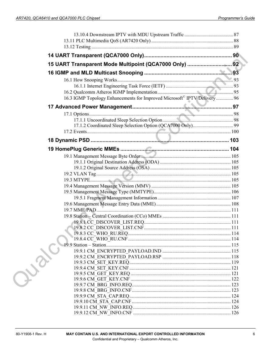
AR7420, QCA6410 and QCA7000 PLC Chipset Programmer’s Guide Q ualco m m Atheros Confidential 13.10.4 Downstream IPTV with MDU Upstream Traffic ........................................ 87 13.11 PLC Multimedia QoS (AR7420 Only) ................................................................... 88 13.12 Testing .................................................................................................................... 89 14 UART Transparent (QCA7000 Only) ........................................................... 90 15 UART Transparent Mode Multipoint (QCA7000 Only) .............................. 92 16 IGMP and MLD Multicast Snooping ........................................................... 93 16.1 How Snooping Works ............................................................................................... 93 16.1.1 Internet Engineering Task Force (IETF) ....................................................... 93 16.2 Qualcomm Atheros IGMP Implementation .............................................................. 95 16.3 IGMP Topology Enhancements for Improved Microsoft© IPTV Delivery .............. 96 17 Advanced Power Management ................................................................... 97 17.1 Options ...................................................................................................................... 98 17.1.1 Uncoordinated Sleep Selection Option .......................................................... 98 17.1.2 Coordinated Sleep Selection Option (QCA7000 Only) ................................. 99 17.2 Events...................................................................................................................... 100 18 Dynamic PSD ............................................................................................. 103 19 HomePlug Generic MMEs ......................................................................... 104 19.1 Management Message Byte Order .......................................................................... 105 19.1.1 Original Destination Address (ODA) .......................................................... 105 19.1.2 Original Source Address (OSA) .................................................................. 105 19.2 VLAN Tag .............................................................................................................. 105 19.3 MTYPE ................................................................................................................... 105 19.4 Management Message Version (MMV) ................................................................. 105 19.5 Management Message Type (MMTYPE) ............................................................... 106 19.5.1 Fragment Management Information ............................................................ 107 19.6 Management Message Entry Data (MME) ............................................................. 108 19.7 MME PAD .............................................................................................................. 111 19.8 Station – Central Coordination (CCo) MMEs ........................................................ 111 19.8.1 CC_DISCOVER_LIST.REQ ....................................................................... 111 19.8.2 CC_DISCOVER_LIST.CNF ....................................................................... 111 19.8.3 CC_WHO_RU.REQ .................................................................................... 114 19.8.4 CC_WHO_RU.CNF .................................................................................... 114 19.9 Station – Station ...................................................................................................... 115 19.9.1 CM_ENCRYPTED_PAYLOAD.IND ........................................................ 115 19.9.2 CM_ENCRYPTED_PAYLOAD.RSP ........................................................ 118 19.9.3 CM_SET_KEY.REQ ................................................................................... 119 19.9.4 CM_SET_KEY.CNF ................................................................................... 121 19.9.5 CM_GET_KEY.REQ .................................................................................. 121 19.9.6 CM_GET_KEY.CNF .................................................................................. 122 19.9.7 CM_BRG_INFO.REQ ................................................................................. 123 19.9.8 CM_BRG_INFO.CNF ................................................................................. 123 19.9.9 CM_STA_CAP.REQ ................................................................................... 124 19.9.10 CM_STA_CAP.CNF ................................................................................. 124 19.9.11 CM_NW_INFO.REQ ................................................................................ 126 19.9.12 CM_NW_INFO.CNF ................................................................................ 126 80-Y1908-1 Rev. H MAY CONTAIN U.S. AND INTERNATIONAL EXPORT CONTROLLED INFORMATION 6 Confidential and Proprietary – Qualcomm Atheros, Inc.
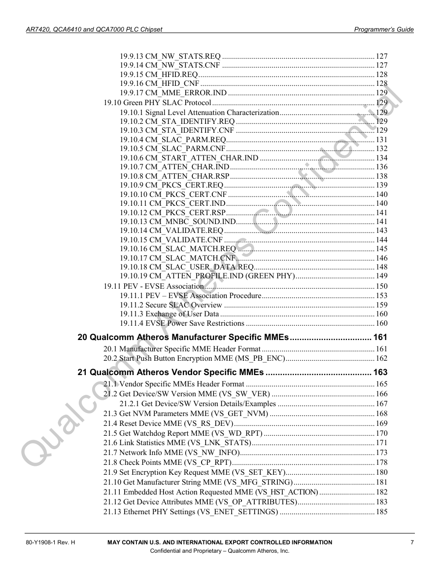
AR7420, QCA6410 and QCA7000 PLC Chipset Programmer’s Guide Q ualco m m Atheros Confidential 19.9.13 CM_NW_STATS.REQ ............................................................................. 127 19.9.14 CM_NW_STATS.CNF ............................................................................. 127 19.9.15 CM_HFID.REQ ......................................................................................... 128 19.9.16 CM_HFID_CNF ........................................................................................ 128 19.9.17 CM_MME_ERROR.IND .......................................................................... 129 19.10 Green PHY SLAC Protocol .................................................................................. 129 19.10.1 Signal Level Attenuation Characterization ................................................ 129 19.10.2 CM_STA_IDENTIFY.REQ ...................................................................... 129 19.10.3 CM_STA_IDENTIFY.CNF ...................................................................... 129 19.10.4 CM_SLAC_PARM.REQ ........................................................................... 131 19.10.5 CM_SLAC_PARM.CNF ........................................................................... 132 19.10.6 CM_START_ATTEN_CHAR.IND .......................................................... 134 19.10.7 CM_ATTEN_CHAR.IND ......................................................................... 136 19.10.8 CM_ATTEN_CHAR.RSP ......................................................................... 138 19.10.9 CM_PKCS_CERT.REQ ............................................................................ 139 19.10.10 CM_PKCS_CERT.CNF .......................................................................... 140 19.10.11 CM_PKCS_CERT.IND ........................................................................... 140 19.10.12 CM_PKCS_CERT.RSP ........................................................................... 141 19.10.13 CM_MNBC_SOUND.IND...................................................................... 141 19.10.14 CM_VALIDATE.REQ ............................................................................ 143 19.10.15 CM_VALIDATE.CNF ............................................................................ 144 19.10.16 CM_SLAC_MATCH.REQ ..................................................................... 145 19.10.17 CM_SLAC_MATCH.CNF ...................................................................... 146 19.10.18 CM_SLAC_USER_DATA.REQ ............................................................. 148 19.10.19 CM_ATTEN_PROFILE.IND (GREEN PHY) ........................................ 149 19.11 PEV - EVSE Association ...................................................................................... 150 19.11.1 PEV – EVSE Association Procedure ......................................................... 153 19.11.2 Secure SLAC Overview ............................................................................ 159 19.11.3 Exchange of User Data .............................................................................. 160 19.11.4 EVSE Power Save Restrictions ................................................................. 160 20 Qualcomm Atheros Manufacturer Specific MMEs .................................. 161 20.1 Manufacturer Specific MME Header Format ......................................................... 161 20.2 Start Push Button Encryption MME (MS_PB_ENC) ............................................. 162 21 Qualcomm Atheros Vendor Specific MMEs ............................................ 163 21.1 Vendor Specific MMEs Header Format ................................................................. 165 21.2 Get Device/SW Version MME (VS_SW_VER) .................................................... 166 21.2.1 Get Device/SW Version Details/Examples ................................................. 167 21.3 Get NVM Parameters MME (VS_GET_NVM) ..................................................... 168 21.4 Reset Device MME (VS_RS_DEV) ....................................................................... 169 21.5 Get Watchdog Report MME (VS_WD_RPT) ........................................................ 170 21.6 Link Statistics MME (VS_LNK_STATS) .............................................................. 171 21.7 Network Info MME (VS_NW_INFO) .................................................................... 173 21.8 Check Points MME (VS_CP_RPT) ........................................................................ 178 21.9 Set Encryption Key Request MME (VS_SET_KEY) ............................................. 180 21.10 Get Manufacturer String MME (VS_MFG_STRING) ......................................... 181 21.11 Embedded Host Action Requested MME (VS_HST_ACTION) ............................ 182 21.12 Get Device Attributes MME (VS_OP_ATTRIBUTES) ....................................... 183 21.13 Ethernet PHY Settings (VS_ENET_SETTINGS) ................................................ 185 80-Y1908-1 Rev. H MAY CONTAIN U.S. AND INTERNATIONAL EXPORT CONTROLLED INFORMATION 7 Confidential and Proprietary – Qualcomm Atheros, Inc.
AR7420, QCA6410 and QCA7000 PLC Chipset Programmer’s Guide 21.14 Tone Map Characteristics MME (VS_TONE_MAP_CHAR) .............................. 187 21.15 Network Information & Statistics MME (VS_NW_INFO_STATS).................... 190 21.16 Reset to Factory Defaults MME (VS_FAC_DEFAULTS) .................................. 195 21.17 Multicast Group Info MME (VS_MULTICAST_INFO) ..................................... 196 21.18 Classification Setting MME (VS_CLASSIFICATION) ....................................... 200 21.19 Receive Tone Map Characteristics MME (VS_RX_TONE_MAP_CHAR) ........ 207 21.20 Set LED Behaviors MME (VS_SET_LED_BEHAVIOR) ................................... 211 21.21 Write and Execute Applet MME (VS_WRITE_AND_EXECUTE_APPLET) .... 214 21.22 Read or Write MDIO Settings (VS_MDIO_COMMAND) .................................. 217 21.23 Static Neighbor Network Mitigation Operation MME (VS_NN_MITIGATE) ... 219 21.24 Module Operation MME (VS_MODULE_OPERATION) .................................. 221 21.25 Diagnostic Network Probe MME (VS_DIAG_NETWORK_PROBE) ................ 229 21.26 Powerline Link Status MME (VS_PL_LNK_STATUS) ...................................... 231 21.27 GPIO State Change MME (VS_GPIO_STATE_CHANGE) ............................... 232 21.28 Multi-Port Link Status MME (VS_MULTIPORT_LNK_STA)............................... 235 21.29 Standby MME (VS_STANDBY) ......................................................................... 236 21.30 Sleep Schedule MME (VS_SLEEPSCHEDULE) ................................................ 238 21.31 Sleep Schedule Notification MME Q ualco m m Atheros Confidential (VS_SLEEPSCHEDULE_NOTIFICATION) ......................................................... 239 21.32 Microcontroller Diagnostics MME (VS_MICROCONTROLLER_DIAG) ......... 239 21.33 Get Property MME (VS_GET_PROPERTY)....................................................... 241 21.34 Set Property MME (VS_SET_PROPERTY) ........................................................ 244 21.35 Attenuation Characteristics MME (VS_ATTEN_CHAR) ................................... 247 22 QCA7000 SPI Device Driver ...................................................................... 248 22.1 SPI Frame Encapsulation ........................................................................................ 248 22.2 SPI Requirements ................................................................................................... 249 22.3 SPI Transfers ........................................................................................................... 250 22.4 Legacy vs. Burst Transfer Modes ........................................................................... 251 22.5 Write Buffer Sequence ............................................................................................ 251 22.5.1 Register List and Control Bits ..................................................................... 251 22.5.2 Reading an QCA7000 Register over SPI ..................................................... 252 22.5.3 Writing an QCA7000 Register over SPI ...................................................... 252 22.5.4 Writing a Packet over SPI ............................................................................ 252 22.6 How is a SPI Frame Constructed? .......................................................................... 252 22.7 Basic Network Driver Operations for QCA7000 SPI Interface .............................. 252 22.8 Handling the QCA7000 Interrupt ........................................................................... 253 22.9 Consider Enabling All Interrupts ............................................................................ 254 22.10 Handling Initialization .......................................................................................... 254 22.11 Transmit Considerations ....................................................................................... 255 22.12 Receive Considerations ......................................................................................... 255 22.13 Known QCA7000 Differences from the PL14 ..................................................... 255 23 QCA7000 UART Interface .......................................................................... 256 23.1 UART Frame Encapsulation ................................................................................... 256 23.2 UART Requirements .............................................................................................. 257 23.3 UART Driver Architecture ..................................................................................... 258 80-Y1908-1 Rev. H MAY CONTAIN U.S. AND INTERNATIONAL EXPORT CONTROLLED INFORMATION 8 Confidential and Proprietary – Qualcomm Atheros, Inc.
分享到:
收藏