logo资料库

CC-Link通信说明书.pdf

第1页 / 共26页
第2页 / 共26页
第3页 / 共26页
第4页 / 共26页
第5页 / 共26页
第6页 / 共26页
第7页 / 共26页
第8页 / 共26页
资料共26页,剩余部分请下载后查看
Contents
Chapter 1 Overview
Chapter 2 Specifications
CC-Link communication specifications
Compatible PLC and applicable master/local unit
Chapter 3 Settings at the V6 side and wiring
Installation to the V6 and the settings
Interface unit
Dimensions of CC-Link I/F unit
How to install a CC-Link I/F unit
Settings at CC-Link I/F unit side
Outline of the CC-Link I/F unit
Settings of transmission speed
Mode setting
Station number setting
Condition setting
Wiring
Wiring
Chapter 4 Connection to the PLC
Available memory
Settings of the master station
Setting of master ・ local unit
Parameter setting
[Sample program]
Notes
Master ・ local unit
Chapter 5 Screen data editing
System setting
Selecting PLC type
Communication parameters
Chapter 6 Errors
Output signal status when the V6 has an error
Error messages on the V6 unit
Station Number Error
Word Writing to Op. Relay (Mitsubishi A series only.)
I/F Board Err
Checking errors by the LED display
Back to Manual List
run stop - - - - - - - - - - - - - - - - - - - - - - - - - - - - - - - - - - - - - - - - - - - - - - - - 5 4 E F 0 7 8 0 STATION NO. MODE 9 A B C D 6 7 8 1 2 3 1 2 3 6 7 8 ON 1 2 4 5 6 3 0 2 1 5 4 9 9 3 4 5 6 7 8 - - - - - - B RATE V612 V608 V610 V608 V608
Contents Chapter 1 Overview....................................................... 1-1 Chapter 2 Specifications .............................................. 2-1 CC-Link communication specifications .............................................. 2-1 Compatible PLC and applicable master/local unit.............................. 2-2 Chapter 3 Settings at the V6 side and wiring ............. 3-1 Installation to the V6 and the settings ................................................ 3-1 Interface unit ................................................................................... 3-1 Dimensions of CC-Link I/F unit ....................................................... 3-1 How to install a CC-Link I/F unit ..................................................... 3-2 Settings at CC-Link I/F unit side......................................................... 3-3 Outline of the CC-Link I/F unit ....................................................... 3-3 Settings of transmission speed ....................................................... 3-3 Mode setting ................................................................................... 3-3 Station number setting .................................................................... 3-3 Condition setting ............................................................................. 3-4 Wiring ............................................................................................. 3-4 Wiring ................................................................................................. 3-5 Chapter 4 Connection to the PLC ................................ 4-1 Available memory ............................................................................... 4-1 Settings of the master station ............................................................. 4-2 Setting of master • local unit AJ61BT11/A1SJ61BT11/AJ61QBT11/A1SJ61QBT11 ..................... 4-2 Parameter setting ........................................................................... 4-3 [Sample program] ................................................................................ 4-4 Notes .................................................................................................. 4-5 Master • local unit ........................................................................... 4-5
Chapter 5 Screen data editing ..................................... 5-1 System setting.................................................................................... 5-1 Selecting PLC type ......................................................................... 5-1 Communication parameters ........................................................... 5-1 Chapter 6 Errors ............................................................ 6-1 Output signal status when the V6 has an error .................................. 6-1 Error messages on the V6 unit........................................................... 6-1 Station Number Error...................................................................... 6-1 Word Writing to Op. Relay (Mitsubishi A series only.) .................. 6-2 I/F Board Err ................................................................................... 6-2 Checking errors by the LED display ................................................... 6-2
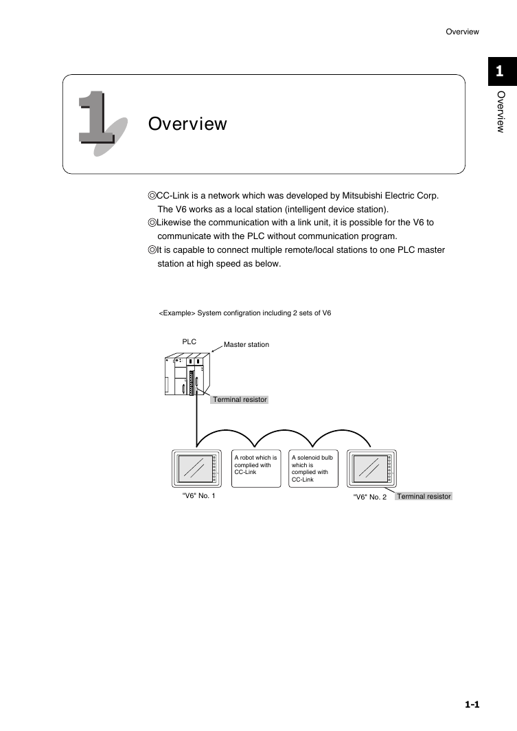
11 Overview Overview 1 O v e r v e w i CC-Link is a network which was developed by Mitsubishi Electric Corp. The V6 works as a local station (intelligent device station). Likewise the communication with a link unit, it is possible for the V6 to communicate with the PLC without communication program. It is capable to connect multiple remote/local stations to one PLC master station at high speed as below. System configration including 2 sets of V6 PLC run stop . . . . . . . . . . . . . . . . . . . . . . . . . . . . . . . . . . . . . . . . . . . . . . . . Master station Terminal resistor A robot which is complied with CC-Link A solenoid bulb which is complied with CC-Link "V6" No. 1 "V6" No. 2 Terminal resistor 1-1
Overview Please use this page freely. 1-2
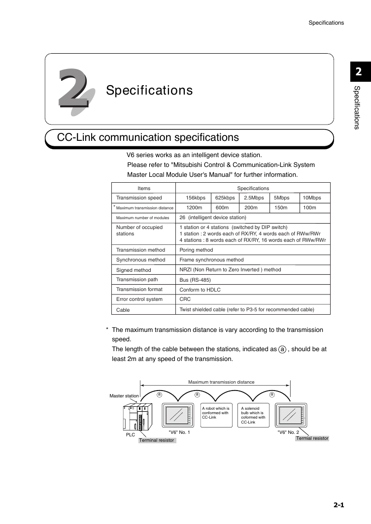
22 Specifications CC-Link communication specifications Specifications 2 S p e c i f i c a t i o n s V6 series works as an intelligent device station. Please refer to "Mitsubishi Control & Communication-Link System Master Local Module User's Manual" for further information. Items Specifications Transmission speed 156kbps 625kbps 2.5Mbps 5Mbps 10Mbps * Maximum transmission distance 1200m 600m 200m 150m 100m Maximum number of modules 26 (intelligent device station) Number of occupied stations 1 station or 4 stations (switched by DIP switch) 1 station : 2 words each of RX/RY, 4 words each of RWw/RWr 4 stations : 8 words each of RX/RY, 16 words each of RWw/RWr Transmission method Poring method Synchronous method Frame synchronous method Signed method NRZI (Non Return to Zero Inverted ) method Transmission path Bus (RS-485) Transmission format Conform to HDLC Error control system CRC Cable Twist shielded cable (refer to P3-5 for recommended cable) * The maximum transmission distance is vary according to the transmission speed. The length of the cable between the stations, indicated as a , should be at least 2m at any speed of the transmission. Master station a a a Maximum transmission distance run stop . . . . . . . . . . . . . . . . . . . . . . . . . . . . . . . . . . . . . . . . . . . . . . . . A robot which is conformed with CC-Link A solenoid bulb which is coformed with CC-Link PLC "V6" No. 1 Terminal resistor "V6" No. 2 Termial resistor 2-1
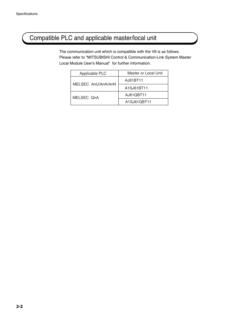
Specifications Compatible PLC and applicable master/local unit The communication unit which is compatible with the V6 is as follows. Please refer to "MITSUBISHI Control & Communication-Link System Master Local Module User's Manual" for further information. Applicable PLC Master or Local Unit MELSEC AnU/AnA/AnN MELSEC QnA AJ61BT11 A1SJ61BT11 AJ61QBT11 A1SJ61QBT11 2-2
分享到:
收藏