硕士研究生 生整些
指导教师
董堡型丝
学科专业
通信与信息墨缠
论文提交日期至!!!圭堡旦 论文答辩日期呈Q!!生!旦
论文评阅人虚基 剑耋咝
重鏖叠垫盘堂
型塑堂塾撞丝壹兰垫±三些苤旦三±查堑
答辩委员会主席张治中教授 重庆邮电大学
2011年5月28日
�
�
独创性声明
本人声明所呈交的学位论文是本人在导师指导下进行的研究工作及取得的研
究成果。据我所知,除了文中特别加以标注和致谢的地方外,论文中不包含其他
人已经发表或撰写过的研究成果,也不包含为获得重废自g电太堂或其他教育
机构的学位或证书而使用过的材料。与我一同工作的同志对本研究所做的任何贡
献均己在论文中作了明确的说明并表示谢意。
学位论文作者签名:9眵影≮缈签字日期:乙。(1年明2暑日
学位论文版权使用授权书
本学位论文作者完全了解 重迭由E电太堂 有关保留、使用学位论文的规
定,有权保留并向国家有关部门或机构送交论文的复印件和磁盘,允许论文被查
阅和借阅。本人授权 重迭由&电太堂 可以将学位论文的全部或部分内容编入
有关数据库进行检索,可以采用影印、缩印或扫描等复制手段保存、汇编学位论
文。
(保密的学位论文在解密后适用本授权书)
学位论文作者签名:卿
签字日期:讼f f年岁月2 8日
新繇罐,馁、
签字日期:锄cF 9砧日
�
�
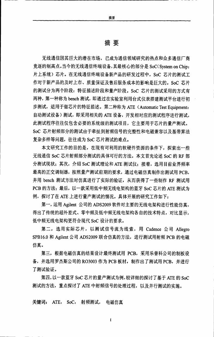
摘要
摘要
无线通信因其巨大的潜在市场,已成为通信领域研究的热点和众多通信厂商
竞逐的制高点。当今的无线通信终端设备,其最核心的部分是SoC(System on Chip:
片上系统)芯片。在无线通信终端设备新产品的研发过程中,SoC芯片的测试工
作对于新产品的及时上市、质量保证及售后服务成本的影响是巨大的。SoC芯片
的测试分为两个阶段:特征描述阶段和量产阶段。SoC芯片的测试采用的方式有
两种,第一种称为bench测试,即通过在实验室利用台式仪表搭建测试平台进行初
步测试,适用于做芯片的特征描述。第二种称为ATE(Automatic Test Equipment:
自动测试设备)测试,即采用相关的ATE设备,开发相对应的测试程序进行测试,
此测试程序往往仅包含必要的系统级的测试项目,它主要用于芯片的量产测试。
SoC芯片射频部分的测试由于牵扯到射频信号的完整性和电磁兼容以及基带算法
复杂多样等问题,往往成为SoC芯片测试的难点。
本文研究工作的目的是,在现有可利用的软硬件资源的条件下,探索出一些
无线通信SoC芯片射频部分测试的具体可行的方法。本文首先论述SoC的RF部
分测试现状;其次,介绍SoC测试理论和ATE测试仪;接着,选用目前业界频率
最高的正交调制器,按照量产测试前期的要求,通过电磁仿真制作出测试用PCB,
并用bench测试方法对仿真进行了实际的验证,从而获得了一些制作RF测试用
PCB的方法;最后,以一款采用低中频无线电架构的蓝牙SoC芯片的ATE测试为
例,探讨了在ATE上进行量产测试的情况。具体开展的研究工作如下:
第一,运用A百lent公司的ADS2009软件对主要的无线电架构进行性能仿真,
得出了传统的超外差式、零中频及低中频无线电架构各自的技术特点,对比显示,
低中频无线电架构更符合现代SoC设计的要求。
第二,选用实际芯片,以测试信号流为线索,用Cadence公司Allegro
SPBl6.0和A百lent公司ADS2009联合仿真的方法,进行测试用射频PCB的电磁
仿真。
第三,根据电磁仿真的结果设计最终测试用PCB,采用乐普科公司的制板设
备,并选用罗杰斯公司的R03003作为PCB板材,制作出了测试用PCB,并进行
了测试验证。
第四,以一款蓝牙SoC芯片的量产测试为例,较详细的探讨了基于ATE的SoC
测试的方法,重点探讨了ATE中射频信号的处理过程,以及并行测试的实施。
关键词: ATE, SoC, 射频测试, 电磁仿真
�
�
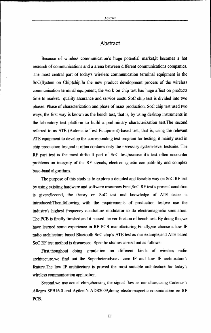
Abstract
Abstract
Because of wireless communication’S huge potential market,it becomes a hot
research of communications and a arena between different communications companies.
The most central part of today's wireless communication terminal equipment is the
SoC(System on Chip)chip.In the new product development process of the wireless
communication terminal equipment,the work on chip test has huge affect Oll products
time to market,quality assurance and service costs.SoC chip test is divided into two
phases:Phase of characterization and phase of mass production.SoC chip test used two
ways,the first way is known as the bench test,that is,by using desktop instruments in
the laboratory test platform to build a preliminary characterization test.The second
referred to as ATE(Automatic Test Equipment)·based test,that is,using the relevant
ATE equipment to develop the corresponding test program for testing,it mainly used in
chip production test,and it often contains only the necessary system-level testsuite.The
RF part test is the most difficult part of SoC test,because it’S test often encounter
problems on integrity of the RF signals,electromagnetic compatibility and complex
base—band algorithms.
The purpose of this study is to explore a detailed and feasible way on SoC RF test
by using existing hardware and software resources.First,SoC RF test’S present condition
is
given;Second,the
theory on SoC test and knowledge
of ATE tester
is
introduced;Then,following with the requirements of production
test,we use the
industrCs highest行equency quadrature modulator to do electromagnetic simulation.
The PCB is finally finished,and it passed the verification of bench test.By doing this,we
have learned some experience in RF PCB manufacturing;Finally,we choose a low IF
radio architecture based Bluetooth SoC chip’S ATE test as Our example,and ATE-based
SoC RF test method is discuessed.Specific studies carried out as follows:
First,thoughout
doing
simulation
on
different
kinds
of
wireless
radio
find out the Superheterodyne,zero IF and low IF architecture’S
architecture,we
feature.The low IF architecture is proved the most suitable architecture for today’S
wireless communication application.
Second,we use actual chip,choosing the signal flow as Our clues,using Cadence’S
Allegro SPB 1 6.0 and Agilent’S ADS2009,doing electromagnetic CO—simulation on RF
PCB.
III
�
_————-l_-—————————————-———————-—-———————-_—_——————————-—_—一
重庆邮电大学硕士论文
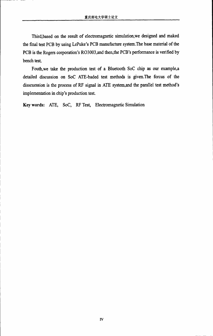
Third,based on the result of electromagnetic simulation,we designed and maked
the final test PCB by using LePuke’S PCB manufacture system.The base material of the
PCB is the Rogers corporation’S R03003,and then,me PCB’S performance is verified by
bench test.
Fouth,we take the production test of a Bluetooth SoC chip as our example,a
detailed discussion on SoC ATE-baded lest methods is given.The forcus of the
disscuession is the process of RF signal in ATE system,and the parallel test method’S
implementation in chip’S production test.
Key words:ATE,SoC,RF Test,Electromagnetic Simulation
IV
�


 2023年江西萍乡中考道德与法治真题及答案.doc
 2012年重庆南川中考生物真题及答案.doc
 2013年江西师范大学地理学综合及文艺理论基础考研真题.doc
 2020年四川甘孜小升初语文真题及答案I卷.doc
 2020年注册岩土工程师专业基础考试真题及答案.doc
 2023-2024学年福建省厦门市九年级上学期数学月考试题及答案.doc
 2021-2022学年辽宁省沈阳市大东区九年级上学期语文期末试题及答案.doc
 2022-2023学年北京东城区初三第一学期物理期末试卷及答案.doc
 2018上半年江西教师资格初中地理学科知识与教学能力真题及答案.doc
 2012年河北国家公务员申论考试真题及答案-省级.doc
 2020-2021学年江苏省扬州市江都区邵樊片九年级上学期数学第一次质量检测试题及答案.doc
 2022下半年黑龙江教师资格证中学综合素质真题及答案.doc