Firmware Programing Guide
ITE Embedded Controller
Firmware Programing Guide
ITE TECH. INC.
www.ite.com.tw
�
Firmware Programing Guide
Copyright 2009 ITE Tech. Inc.
All specifications are subject to change without notice. The material contained in this document
supersedes all previous documentation issued for the related products included herein. Please contact ITE
Tech. Inc. for the latest document(s).
All sales are subject to ITE’s Standard Terms and Conditions, a copy of which is included in the back of this
document.
All other trademarks are claimed by their respective owners.
All specifications are subject to change without notice.
Additional copies of this manual or other ITE literature may be obtained from:
If you have any marketing or sales questions, please contact:
ITE Tech. Inc.
Marketing Department
7F, No. 233-1, Baociao Rd., Sindian City,
Taipei County 23145, Taiwan, R.O.C.
(02) 29126889
(02) 2910-2551, 2910-2552
Phone:
Fax:
P.Y. Chang, at ITE Taiwan: E-mail: p.y.chang@ite.com.tw, Tel: 886-2-29126889 X6052,
Fax: 886-2-29102551
http://www.ite.com.tw
To find out more about ITE, visit our World Wide Web at:
Or e-mail itesupport@ite.com.tw for more product information/services
www.ite.com.tw
1
�
Data
04/09/2012
Firmware Programing Guide
Version History
Version
1.0
Description
First release
www.ite.com.tw
2
�
Firmware Programing Guide
CONTENTS
1.
Introduction ............................................................................................................. 4
1.1
General Description .............................................................................................................. 4
2. Compiler Environment ........................................................................................... 5
Source Code Folder Definition ............................................................................................. 5
Source Code Folder Architecture of Command Line Version ........................................... 5
Source Code Folder Architecture of IDE Version ............................................................... 6
Generating a Bin File of Command Line Version ............................................................... 6
Generating a Bin File of IDE Version ................................................................................... 7
Creating a New C Source File of Command Line Version ................................................. 8
Creating a New C Source File of IDE Version ..................................................................... 9
3. EC Memory Space ................................................................................................. 10
4. Firmware Architecture .......................................................................................... 12
The Start of EC firmware ..................................................................................................... 13
The Main Function of EC Firmware ................................................................................... 14
Interrupt Service Routine .................................................................................................... 17
LPC I/O 60h/64h Interface ................................................................................................... 23
LPC I/O 62h/66h Interface ................................................................................................... 29
PS2 Interface ........................................................................................................................ 32
Internal Keyboard Scanner ................................................................................................. 36
SMBus Interface .................................................................................................................. 43
SPI Read/Write Interface ..................................................................................................... 47
5. Debugging Interface ............................................................................................. 48
KBS Download Board ......................................................................................................... 48
Serial Port of 8032 ............................................................................................................... 51
4.1
4.2
4.3
4.4
4.5
4.6
4.7
4.8
4.9
2.1
2.2
2.3
2.4
2.5
2.6
2.7
5.1
5.2
www.ite.com.tw
3
�
1. Introduction
1.1 General Description
Firmware Programing Guide
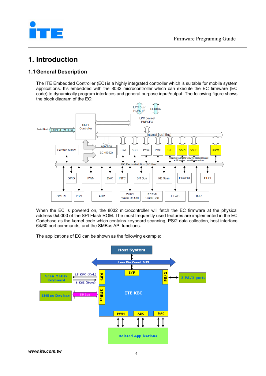
The ITE Embedded Controller (EC) is a highly integrated controller which is suitable for mobile system
applications. It’s embedded with the 8032 microcontroller which can execute the EC firmware (EC
code) to dynamically program interfaces and general purpose input/output. The following figure shows
the block diagram of the EC:
When the EC is powered on, the 8032 microcontroller will fetch the EC firmware at the physical
address 0x0000 of the SPI Flash ROM. The most frequently used features are implemented in the EC
Codebase as the kernel code which contains keyboard scanning, PS/2 data collection, host interface
64/60 port commands, and the SMBus API functions.
The applications of EC can be shown as the following example:
www.ite.com.tw
4
�
Firmware Programing Guide
2. Compiler Environment
The Keil C components (C51, A51, and BL51) are requested for generating bin file of EC firmware.
Please make sure Keil C is properly installed and containing at least these components before
generating bin file. Other necessary firmware utilities are included in the source code.
2.1 Source Code Folder Definition
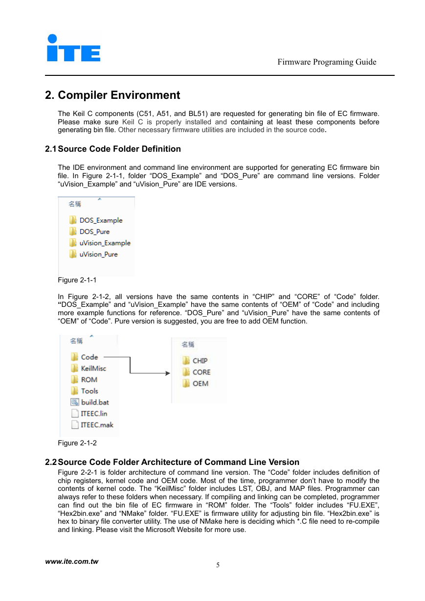
The IDE environment and command line environment are supported for generating EC firmware bin
file. In Figure 2-1-1, folder “DOS_Example” and “DOS_Pure” are command line versions. Folder
“uVision_Example” and “uVision_Pure” are IDE versions.
Figure 2-1-1
In Figure 2-1-2, all versions have the same contents in “CHIP” and “CORE” of “Code” folder.
“DOS_Example” and “uVision_Example” have the same contents of “OEM” of “Code” and including
more example functions for reference. “DOS_Pure” and “uVision_Pure” have the same contents of
“OEM” of “Code”. Pure version is suggested, you are free to add OEM function.
Figure 2-1-2
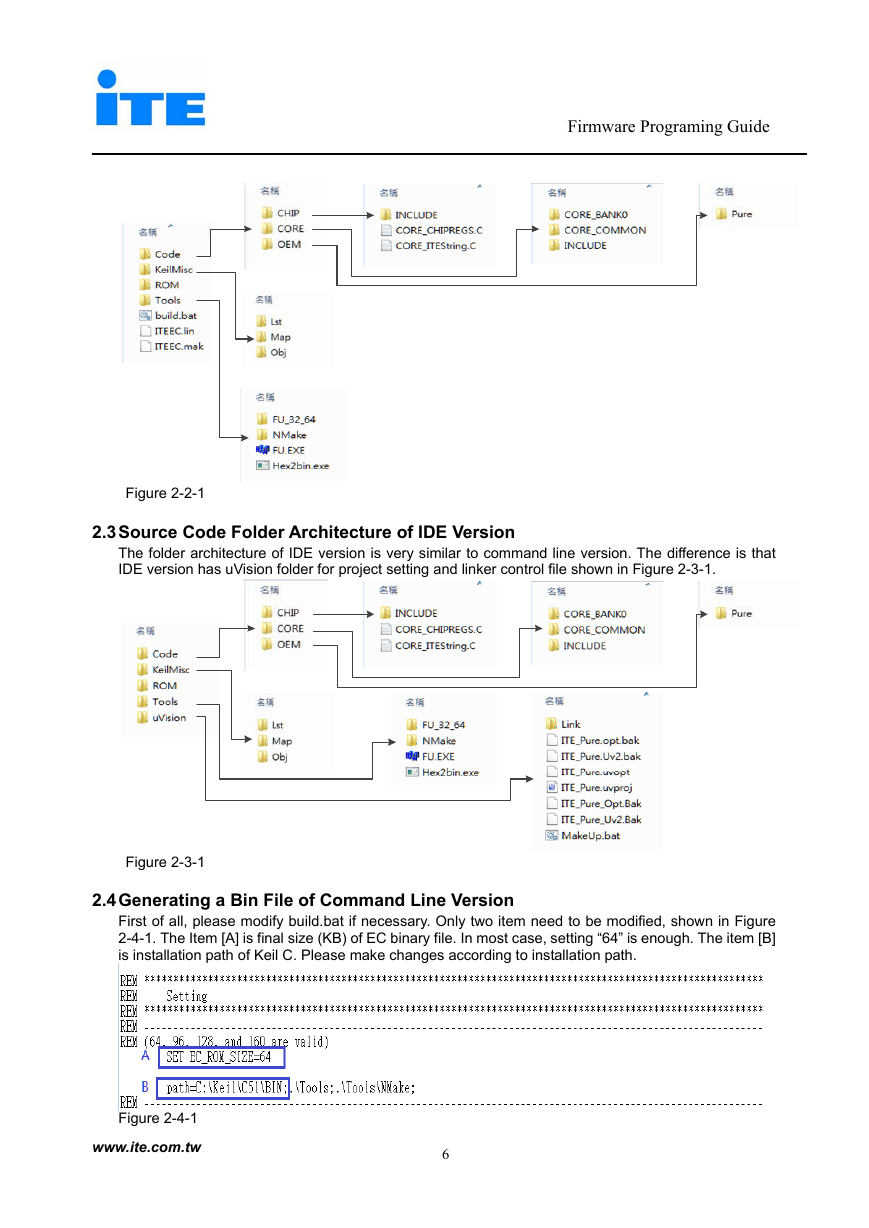
2.2 Source Code Folder Architecture of Command Line Version
Figure 2-2-1 is folder architecture of command line version. The “Code” folder includes definition of
chip registers, kernel code and OEM code. Most of the time, programmer don’t have to modify the
contents of kernel code. The “KeilMisc” folder includes LST, OBJ, and MAP files. Programmer can
always refer to these folders when necessary. If compiling and linking can be completed, programmer
can find out the bin file of EC firmware in “ROM” folder. The “Tools” folder includes “FU.EXE”,
“Hex2bin.exe” and “NMake” folder. “FU.EXE” is firmware utility for adjusting bin file. “Hex2bin.exe” is
hex to binary file converter utility. The use of NMake here is deciding which *.C file need to re-compile
and linking. Please visit the Microsoft Website for more use.
www.ite.com.tw
5
�
Firmware Programing Guide
Figure 2-2-1
2.3 Source Code Folder Architecture of IDE Version
The folder architecture of IDE version is very similar to command line version. The difference is that
IDE version has uVision folder for project setting and linker control file shown in Figure 2-3-1.
Figure 2-3-1
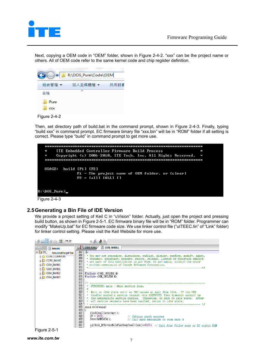
2.4 Generating a Bin File of Command Line Version
First of all, please modify build.bat if necessary. Only two item need to be modified, shown in Figure
2-4-1. The Item [A] is final size (KB) of EC binary file. In most case, setting “64” is enough. The item [B]
is installation path of Keil C. Please make changes according to installation path.
Figure 2-4-1
www.ite.com.tw
6
�
Firmware Programing Guide
Next, copying a OEM code in “OEM” folder, shown in Figure 2-4-2. “xxx” can be the project name or
others. All of OEM code refer to the same kernel code and chip register definition.
Figure 2-4-2
Then, set directory path of build.bat in the command prompt, shown in Figure 2-4-3. Finally, typing
“build xxx” in command prompt. EC firmware binary file “xxx.bin” will be in “ROM” folder if all setting is
correct. Please type “build” in command prompt to get more use.
Figure 2-4-3
2.5 Generating a Bin File of IDE Version
We provide a project setting of Keil C in “uVision” folder. Actually, just open the project and pressing
build button, as shown in Figure 2-5-1. EC firmware binary file will be in “ROM” folder. Programmer can
modify “MakeUp.bat” for EC firmware code size. We use linker control file (“uITEEC.lin” of “Link” folder)
for linker control setting. Please visit the Keil Website for more use.
Figure 2-5-1
www.ite.com.tw
7
�


 2023年江西萍乡中考道德与法治真题及答案.doc
 2012年重庆南川中考生物真题及答案.doc
 2013年江西师范大学地理学综合及文艺理论基础考研真题.doc
 2020年四川甘孜小升初语文真题及答案I卷.doc
 2020年注册岩土工程师专业基础考试真题及答案.doc
 2023-2024学年福建省厦门市九年级上学期数学月考试题及答案.doc
 2021-2022学年辽宁省沈阳市大东区九年级上学期语文期末试题及答案.doc
 2022-2023学年北京东城区初三第一学期物理期末试卷及答案.doc
 2018上半年江西教师资格初中地理学科知识与教学能力真题及答案.doc
 2012年河北国家公务员申论考试真题及答案-省级.doc
 2020-2021学年江苏省扬州市江都区邵樊片九年级上学期数学第一次质量检测试题及答案.doc
 2022下半年黑龙江教师资格证中学综合素质真题及答案.doc