logo资料库

NXP_PN544_DataSheet.pdf

第1页 / 共69页
第2页 / 共69页
第3页 / 共69页
第4页 / 共69页
第5页 / 共69页
第6页 / 共69页
第7页 / 共69页
第8页 / 共69页
资料共69页,剩余部分请下载后查看
1. Introduction
2. General description
3. Features
4. Applications
5. Quick reference data
6. Ordering information
7. Marking
8. Block diagram
9. Pinning information
9.1 Pinning
9.2 Pin description
10. Functional description
10.1 Functional / Power states of PN544
10.1.1 Standby mode
10.1.2 Active R/W mode
10.1.3 Active battery mode
10.1.4 Polling loop
10.1.5 Hard power down (HPD) mode
10.1.6 Monitor mode
10.1.7 Active antenna mode (Powered-by-field)
10.2 Microcontroller HT80C51MX
10.2.1 PN544 memory management
10.2.2 Timer0/1 description
10.2.3 Interrupts management
10.2.4 FW architecture
10.3 Host interfaces
10.3.1 High Speed UART (HSU) Interface
10.3.1.1 HSU configuration options
10.3.2 I2C interface
10.3.2.1 I2C configuration options
10.3.2.2 I2C functional description
10.3.3 Serial Peripheral Interface
10.3.3.1 Features
10.3.3.2 SPI configuration options
10.3.3.3 SPI functional description
10.3.4 IOs configuration
10.3.4.1 Pad configuration description
10.4 Secure element interfaces
10.4.1 SWP interface
10.4.2 NFC-WI interface support
10.5 PN544 clock concept
10.5.1 27.12 MHz crystal oscillator
10.5.2 Integrated FracNpll to make use of cellular clock
10.5.3 Low power 20 MHz oscillator
10.5.4 Low power 333 kHz oscillator
10.6 Supply concept
10.6.1 PN544 supply sources
10.6.2 PMU functional description
10.6.3 Secure element supply
10.6.4 UICC supply
10.6.5 Battery voltage monitor
10.7 Contactless interface Unit
10.7.1 Reader/Writer modes
10.7.1.1 ISO/IEC 14443-A/MIFARE PCD mode
10.7.1.2 FeliCa PCD mode
10.7.1.3 ISO/IEC 14443B PCD mode
10.7.1.4 ISO/IEC 15693 VCD mode
10.7.2 ISO/IEC 18092, ECMA 340 NFCIP-1 operating mode
10.7.2.1 ACTIVE Communication mode
10.7.2.2 PASSIVE Communication mode
10.7.2.3 NFCIP-1 framing and coding
10.7.2.4 NFCIP-1 protocol support
10.7.3 Card Operation mode
10.7.3.1 ISO/IEC 14443-A / MIFARE Card Operation mode
10.7.3.2 ISO/IEC 14443 B and B’ Card Operation mode
11. Application design-in information
12. Limiting values
13. Recommended operating conditions
14. Thermal characteristics
15. Characteristics
15.1 Current consumption characteristics
15.2 Functional block electrical characteristics
15.2.1 Battery voltage monitor characteristics
15.3 Pin characteristics
15.3.1 XTAL pin characteristics (XTAL1, XAL2)
15.3.2 VEN and VEN_MON input pin characteristics
15.3.3 NRESET input pin characteristics
15.3.4 Output pin characteristics for IRQ
15.3.5 Pin characteristics for GPIOs, IF0 and IF1
15.3.6 Pin characteristics for IF2, IF3
15.3.7 SWIO pin characteristics
15.3.8 Output pin characteristics for EXT_SW_CTRL
15.3.9 Input pin characteristics for SIGIN
15.3.10 Output pin characteristics for SIGOUT
15.3.11 Output pin characteristics for AUX1/AUX2/AUX3/AUX4
15.3.12 Input pin characteristics for RX
15.3.13 Output pin characteristics for TX1/TX2
16. Package outline
17. Abbreviations
18. References
19. Revision history
20. Legal information
20.1 Data sheet status
20.2 Definitions
20.3 Disclaimers
20.4 Licenses
20.5 Trademarks
21. Contact information
22. Tables
23. Figures
24. Contents
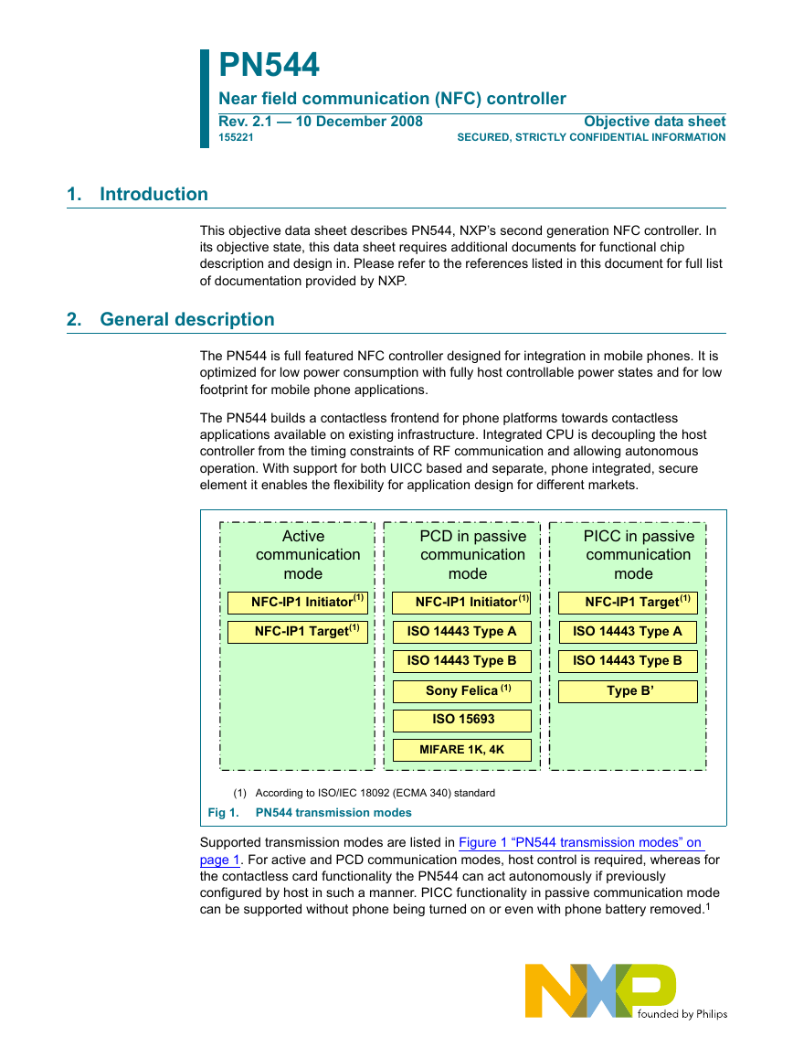
PN544 Near field communication (NFC) controller Rev. 2.1 — 10 December 2008 155221 Objective data sheet SECURED, STRICTLY CONFIDENTIAL INFORMATION 1. Introduction This objective data sheet describes PN544, NXP’s second generation NFC controller. In its objective state, this data sheet requires additional documents for functional chip description and design in. Please refer to the references listed in this document for full list of documentation provided by NXP. 2. General description The PN544 is full featured NFC controller designed for integration in mobile phones. It is optimized for low power consumption with fully host controllable power states and for low footprint for mobile phone applications. The PN544 builds a contactless frontend for phone platforms towards contactless applications available on existing infrastructure. Integrated CPU is decoupling the host controller from the timing constraints of RF communication and allowing autonomous operation. With support for both UICC based and separate, phone integrated, secure element it enables the flexibility for application design for different markets. communication Active mode PCD in passive communication mode PICC in passive communication mode NFC-IP1 Initiator(1) NFC-IP1 Initiator(1) NFC-IP1 Target(1) NFC-IP1 Target(1) ISO 14443 Type A ISO 14443 Type A ISO 14443 Type B ISO 14443 Type B Sony Felica (1) ISO 15693 MIFARE 1K, 4K Type B’ (1) According to ISO/IEC 18092 (ECMA 340) standard Fig 1. PN544 transmission modes Supported transmission modes are listed in Figure 1 “PN544 transmission modes” on page 1. For active and PCD communication modes, host control is required, whereas for the contactless card functionality the PN544 can act autonomously if previously configured by host in such a manner. PICC functionality in passive communication mode can be supported without phone being turned on or even with phone battery removed.1
NXP Semiconductors 3. Features PN544 Near field communication (NFC) controller SECURED, STRICTLY CONFIDENTIAL INFORMATION HT80C51MX low power microcontroller core Code memory: 128 KB ROM, 44 KB EEPROM Data memory: 5KB SRAM, 8 KB EEPROM Highly integrated demodulator and decoder Buffered output drivers to connect an antenna with minimum number of external components Integrated RF level detector Integrated configurable Polling Loop for automatic device discovery RF protocols supported Support of ISO/IEC 14443A, ISO/IEC 14443B, FeliCa PCD mode Supports MIFARE reader encryption mechanism (MIFARE 1K/4K) Supports NFC Forum tag (MIFARE Ultralight, Jewel, FeliCa open tag, DESFire) Support of ISO/IEC 15693/ICODE VCD mode Supports of NFC-IP1 protocol Support of ISO/IEC 14443A, ISO/IEC 14443B card emulation Supported host interfaces High Speed UART (HSU) SPI I2C Supported secure element interfaces SWP/HCI (Single Wire Protocol) according ETSI/SCP standardization Release 7 ISO/IEC 28361 (ECMA 373) NFC-WI interface to connect an external secure IC restricted to 106kb/s. Signal In activation is not implemented. Flexible clock supply concept to facilitate PN544 integration Integrated FracNPLL unit to make use of cellular reference clock Internal oscillator for 27.12 MHz crystal connection Integrated power management unit Direct connection to a mobile battery (2.3 V to 5.5 V voltage supply range) Power switch for secure companion chips connected over SWP or NFC-WI Support different power-down/standby mode by firmware Powered by the field and Powered by the battery mode when mobile is off supported Dedicated IO ports for external device control Flexible interrupts using IRQ pin Automatic host wake up via host control interface Integrated non-volatile memory to store data and executable code for customizing Integrated antenna detector for production tests 1. This functionality is strongly dependent on actual implementation and mechanical constraints (e.g. antenna size) 155221 Objective data sheet Rev. 2.1 — 10 December 2008 © NXP B.V. 2008. All rights reserved. 2 of 69
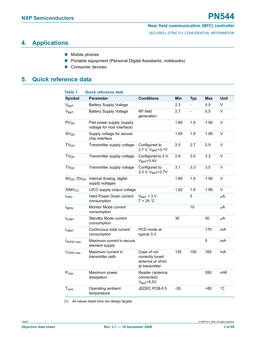
NXP Semiconductors 4. Applications PN544 Near field communication (NFC) controller SECURED, STRICTLY CONFIDENTIAL INFORMATION Mobile phones Portable equipment (Personal Digital Assistants, notebooks) Consumer devices 5. Quick reference data Table 1. Symbol VBAT VBAT Quick reference data Parameter Battery Supply Voltage Battery Supply Voltage Conditions RF field generation PVDD SVDD TVDD TVDD TVDD Pad power supply (supply voltage for host interface) Supply voltage for secure chip interface Transmitter supply voltage Configured to 2.7 V, VBAT>3.1V Transmitter supply voltage Configured to 3 V, VBAT>3.4V Transmitter supply voltage Configured to 3.3 V, VBAT>3.7V AVDD, DVDD Internal Analog, digital SIMVCC IHPD IMON ISTBY IVBAT ISVDD max ITVDD max Pmax Tamb supply voltages UICC supply output voltage Hard Power Down current consumption Monitor Mode current consumption Standby Mode current consumption Continuous total current consumption Maximum current in secure element supply Maximum current in transmitter path Maximum power dissipation Operating ambient temperature VBAT = 3 V T = 25 °C PCD mode at typical 3 V Case of not correctly tuned antenna or short at transmitter Reader (antenna connected) VBAT=5.5V JEDEC PCB-0.5 Typ - - 1.8 1.8 2.7 3.0 3.3 1.8 1.8 5 10 Min 2.3 2.7 1.65 1.65 2.5 2.8 3.1 1.65 1.62 30 Max 5.5 5.5 1.95 1.95 2.9 3.2 3.5 1.95 1.98 50 170 5 135 150 165 Unit V V V V V V V V V μA μA μA mA mA mA 550 mW -30 +85 °C [1] All values listed here are design targets 155221 Objective data sheet Rev. 2.1 — 10 December 2008 © NXP B.V. 2008. All rights reserved. 3 of 69
NXP Semiconductors 6. Ordering information PN544 Near field communication (NFC) controller SECURED, STRICTLY CONFIDENTIAL INFORMATION Table 2. Type number Package Ordering information PN5441A2ET [1] Name TFBGA64 plastic thin fine-pitch ball grid array package; 64 balls; Description body 4.5 × 4.5 × 0.8 mm Version SOT962-1 [1] Refer to ”Section 20.4 “Licenses” 7. Marking Fig 2. PN544 package marking Marking codes B C Table 3. Type number A Marking code Product name including three digits for string ’544’ and two digits for hardware version Diffusion batch sequence number Manufacturing code including: Diffusion center code Assembly center code ROHS compliancy indicator Manufacturing year and week Mask layout version Product life cycle status code 155221 Objective data sheet Rev. 2.1 — 10 December 2008 © NXP B.V. 2008. All rights reserved. 4 of 69
NXP Semiconductors 8. Block diagram UICC Interface SWP SWP Analog UART SE Interface NFC-WI Analog Cless RF detect Sensor Demod ADC Driver TxCtrl BG PLL VMID Contactless Interface Unit (CIU) Cless Co-processor Contactless CoProcessor RX codec TX codec Signal processing PbF :Power by the Field Power Management Unit 1.8V DS-LDO 3V TX-LDO POR PbF SE Supply UICC Supply Battery Monitor Fig 3. PN544 block diagram PN544 Near field communication (NFC) controller SECURED, STRICTLY CONFIDENTIAL INFORMATION Host Interface UART SPI I²C Timer0/1 Interrupt controller GPIO RNG Memory interface CPU HT80C51MX Clock management unit OSC 300kHz FracN PLL OSC 20MHz Quartz oscillator Data Memory SRAM 5KBytes E²PROM 8KBytes ROM 128KBytes E²PROM 44KBytes Progr. Memory 155221 Objective data sheet Rev. 2.1 — 10 December 2008 © NXP B.V. 2008. All rights reserved. 5 of 69
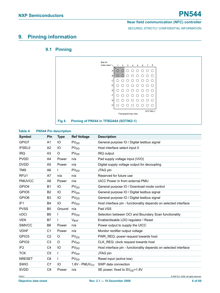
NXP Semiconductors 9. Pinning information 9.1 Pinning PN544 Near field communication (NFC) controller SECURED, STRICTLY CONFIDENTIAL INFORMATION Ball A1 index area 1 2 3 4 5 6 7 8 A B C D E F G H Fig 4. Pinning of PN544 in TFBGA64 (SOT962-1) Transparent top view SOT 962-1 PN544 Pin description Pin A1 A2 A3 A4 A5 A6 A7 A8 B1 B2 B3 B4 B5 B6 B7 B8 C1 C2 C3 C4 C5 C6 C7 C8 Ref Voltage PVDD PVDD PVDD n/a n/a PVDD n/a n/a PVDD PVDD PVDD PVDD Type IO IO O Power Power I n/a Power IO IO IO IO Ground n/a I I Power Power O O IO I I IO Power Description General purpose IO / Digital testbus signal Host interface select input 0 IRQ output Pad supply voltage input (VI/O) Digital supply voltage output for decoupling JTAG pin Reserved for future use UICC Power in from external PMU General purpose IO / Download mode control General purpose IO / Digital testbus signal General purpose IO / Digital testbus signal Host interface pin - functionality depends on selected interface Pad VSS Selection between OCI and Boundary Scan functionality Enable/disable LDO regulator / Reset Power output to supply the UICC Monitor rectifier output voltage PWR_REQ: power request towards host CLK_REQ: clock request towards host Host interface pin - functionality depends on selected interface JTAG pin Reset input (active low) PVDD VBAT n/a n/a PVDD PVDD PVDD PVDD PVDD 1.8V - PMUVCC SWP data connection n/a SE power; fixed to SVDD=1.8V Table 4. Symbol GPIO7 IFSEL0 IRQ PVDD DVDD TMS RFU1 PMUVCC GPIO4 GPIO5 GPIO6 IF1 PVSS nOCI VEN SIMVCC VDHF GPIO3 GPIO2 IF2 TCK NRESET SWIO SVDD 155221 Objective data sheet Rev. 2.1 — 10 December 2008 © NXP B.V. 2008. All rights reserved. 6 of 69
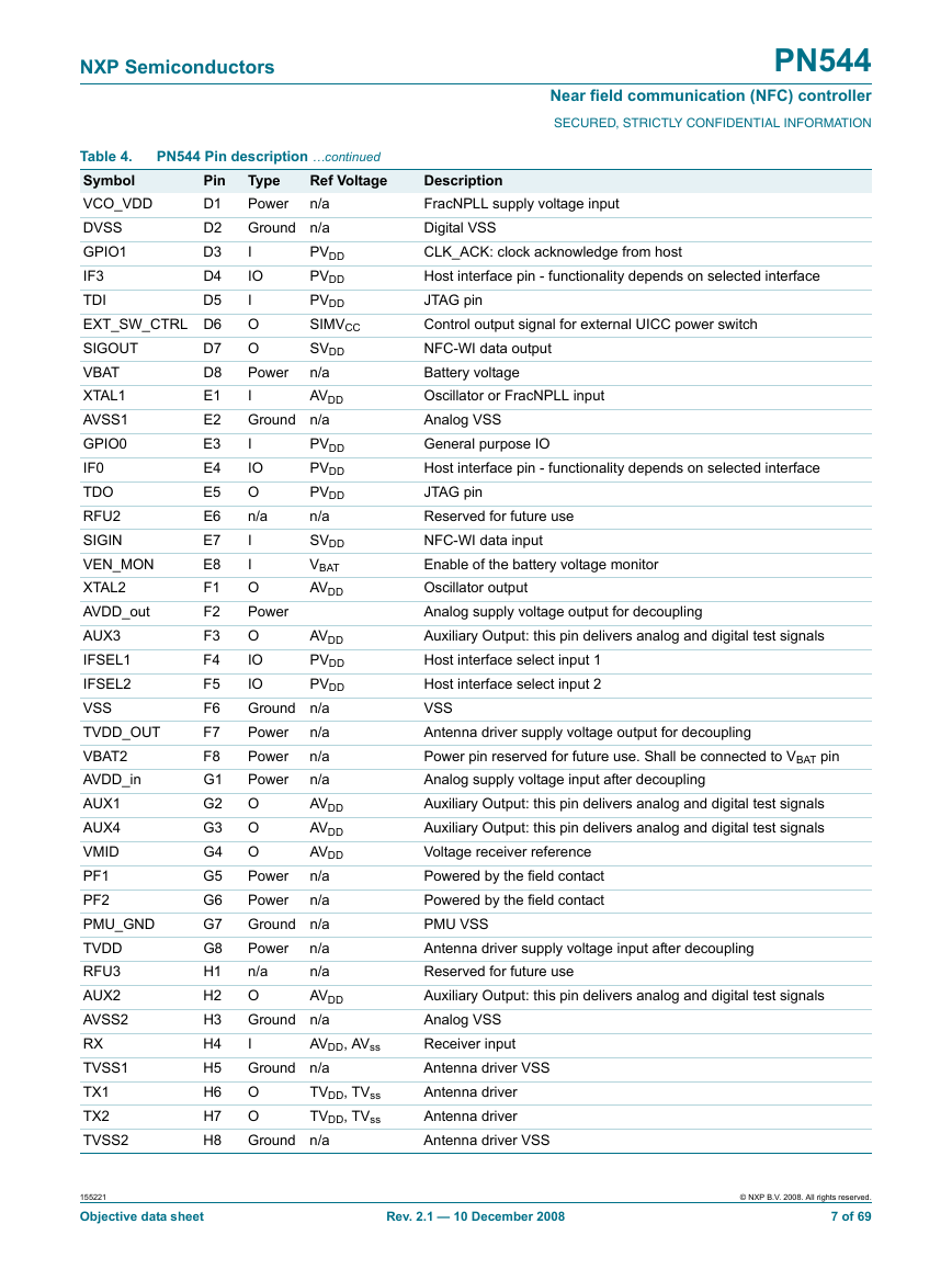
NXP Semiconductors PN544 Near field communication (NFC) controller SECURED, STRICTLY CONFIDENTIAL INFORMATION PVDD PVDD PVDD n/a SVDD VBAT AVDD AVDD PVDD PVDD PVDD PVDD PVDD SIMVCC SVDD n/a AVDD Table 4. Symbol Pin D1 VCO_VDD DVSS D2 GPIO1 D3 IF3 D4 TDI D5 EXT_SW_CTRL D6 D7 SIGOUT VBAT D8 E1 XTAL1 E2 AVSS1 GPIO0 E3 E4 IF0 E5 TDO E6 RFU2 SIGIN E7 E8 VEN_MON F1 XTAL2 AVDD_out F2 F3 AUX3 F4 IFSEL1 IFSEL2 F5 F6 VSS F7 TVDD_OUT F8 VBAT2 AVDD_in G1 G2 AUX1 G3 AUX4 VMID G4 G5 PF1 G6 PF2 PMU_GND G7 G8 TVDD H1 RFU3 H2 AUX2 AVSS2 H3 H4 RX H5 TVSS1 TX1 H6 H7 TX2 TVSS2 H8 PN544 Pin description …continued Ref Voltage Type n/a Power Ground n/a I IO I O O Power I Ground n/a I IO O n/a I I O Power O IO IO Ground n/a n/a Power n/a Power Power n/a AVDD O AVDD O O AVDD n/a Power Power n/a Ground n/a n/a Power n/a n/a O AVDD Ground n/a I Ground n/a O O Ground n/a AVDD, AVss TVDD, TVss TVDD, TVss Description FracNPLL supply voltage input Digital VSS CLK_ACK: clock acknowledge from host Host interface pin - functionality depends on selected interface JTAG pin Control output signal for external UICC power switch NFC-WI data output Battery voltage Oscillator or FracNPLL input Analog VSS General purpose IO Host interface pin - functionality depends on selected interface JTAG pin Reserved for future use NFC-WI data input Enable of the battery voltage monitor Oscillator output Analog supply voltage output for decoupling Auxiliary Output: this pin delivers analog and digital test signals Host interface select input 1 Host interface select input 2 VSS Antenna driver supply voltage output for decoupling Power pin reserved for future use. Shall be connected to VBAT pin Analog supply voltage input after decoupling Auxiliary Output: this pin delivers analog and digital test signals Auxiliary Output: this pin delivers analog and digital test signals Voltage receiver reference Powered by the field contact Powered by the field contact PMU VSS Antenna driver supply voltage input after decoupling Reserved for future use Auxiliary Output: this pin delivers analog and digital test signals Analog VSS Receiver input Antenna driver VSS Antenna driver Antenna driver Antenna driver VSS 155221 Objective data sheet Rev. 2.1 — 10 December 2008 © NXP B.V. 2008. All rights reserved. 7 of 69
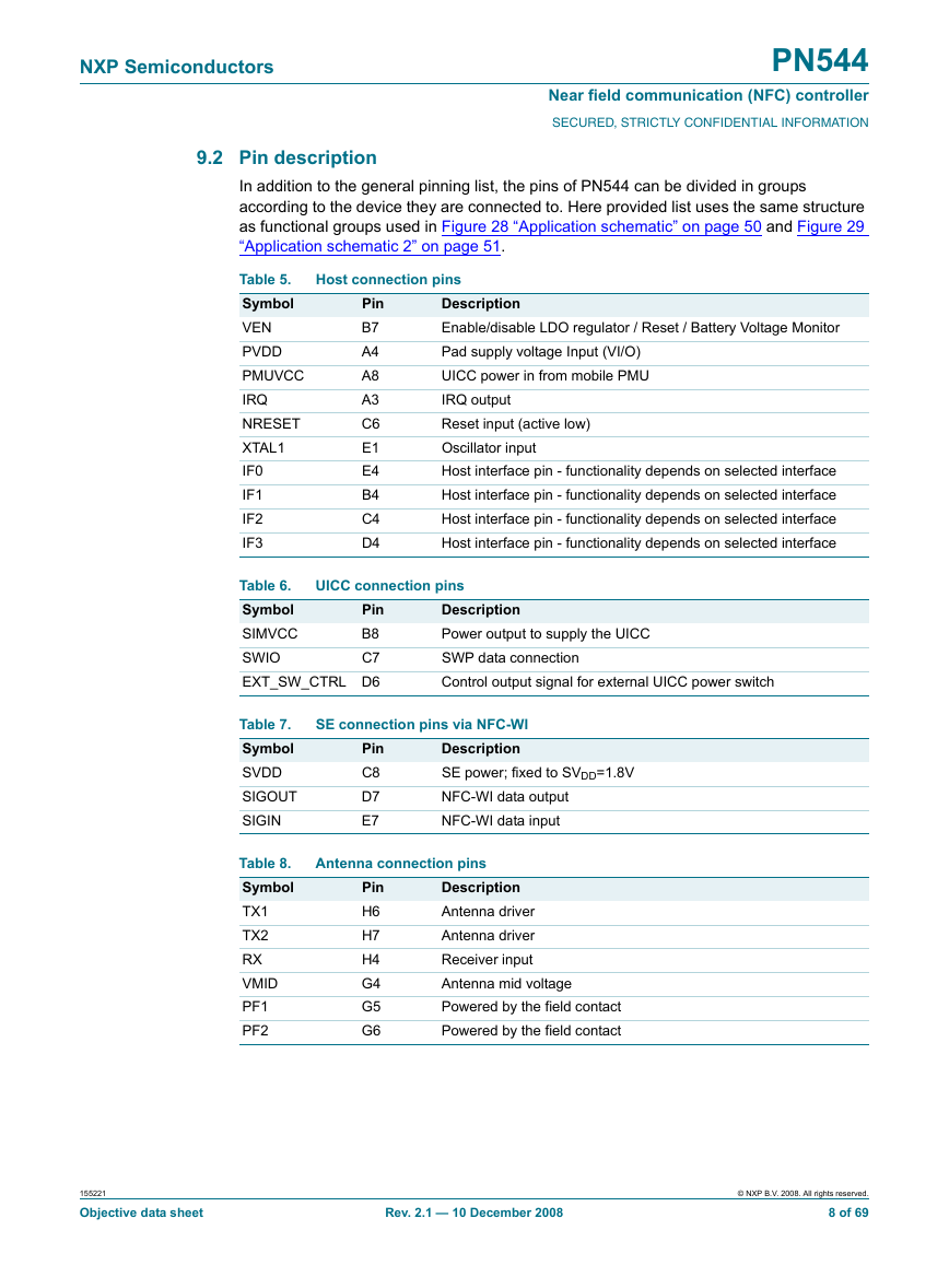
NXP Semiconductors PN544 Near field communication (NFC) controller SECURED, STRICTLY CONFIDENTIAL INFORMATION 9.2 Pin description In addition to the general pinning list, the pins of PN544 can be divided in groups according to the device they are connected to. Here provided list uses the same structure as functional groups used in Figure 28 “Application schematic” on page 50 and Figure 29 “Application schematic 2” on page 51. Table 5. Symbol VEN PVDD PMUVCC IRQ NRESET XTAL1 IF0 IF1 IF2 IF3 Host connection pins Pin B7 A4 A8 A3 C6 E1 E4 B4 C4 D4 Description Enable/disable LDO regulator / Reset / Battery Voltage Monitor Pad supply voltage Input (VI/O) UICC power in from mobile PMU IRQ output Reset input (active low) Oscillator input Host interface pin - functionality depends on selected interface Host interface pin - functionality depends on selected interface Host interface pin - functionality depends on selected interface Host interface pin - functionality depends on selected interface Table 6. Pin Symbol B8 SIMVCC SWIO C7 EXT_SW_CTRL D6 UICC connection pins Description Power output to supply the UICC SWP data connection Control output signal for external UICC power switch Table 7. Symbol SVDD SIGOUT SIGIN Table 8. Symbol TX1 TX2 RX VMID PF1 PF2 SE connection pins via NFC-WI Description SE power; fixed to SVDD=1.8V NFC-WI data output NFC-WI data input Pin C8 D7 E7 Antenna connection pins Pin H6 H7 H4 G4 G5 G6 Description Antenna driver Antenna driver Receiver input Antenna mid voltage Powered by the field contact Powered by the field contact 155221 Objective data sheet Rev. 2.1 — 10 December 2008 © NXP B.V. 2008. All rights reserved. 8 of 69
分享到:
收藏