OCP Mezzanine card 2.0 Design
Specification
Version 1.00
Author: Jia Ning, Engineer, Facebook
�
1 Contents
1 Contents ................................................................................................................................................... 2
2 Overview .................................................................................................................................................. 4
2.1 License .............................................................................................................................................................. 4
2.2 Background ..................................................................................................................................................... 4
2.3 New Use Cases ............................................................................................................................................... 4
2.4 Major Changes to Form Factor ................................................................................................................. 5
2.5 Major Changes to Electrical Interface ................................................................................................... 5
3 Mezzanine Card Form Factor ............................................................................................................ 5
3.1 Primary and Secondary Side Definition ................................................................................................ 5
3.2 Mezzanine Card Connectors ..................................................................................................................... 6
3.3 Form Factor Definition in Horizontal Plane ........................................................................................ 7
3.3.1 Optional Area for Connector B .......................................................................................................... 9
3.3.2 Optional Area for I/O ............................................................................................................................ 9
3.3.3 Connector C Area ................................................................................................................................... 9
3.4 Form Factor Vertical Stack Definition ................................................................................................ 10
3.5
Implementation Examples ..................................................................................................................... 12
3.5.1 Single/Dual Port SFP+ 10G/SFP28 25G Ethernet Mezzanine Card (Type 1) ...................... 13
3.5.2 Dual QSFP+ Port 40G Mezzanine Card (Type 1) ......................................................................... 13
3.5.3 Dual QSFP+ Port 40G Mezzanine card (Type 2) ......................................................................... 14
3.5.4 Quad SFP+ port 10G Mezzanine card (Type 3) ........................................................................... 15
3.5.5 Quad port 10G Base-T Mezzanine Card (Type 3) ....................................................................... 16
3.5.6 Dual Port QSFP28 Style A/Style B 50G/100G Mezzanine Card (Type 1) .............................. 17
3.5.7 Quad Port 10GBaseT RJ45 KR Mezzanine card with Connector C (Type 2) ....................... 18
3.5.8 Quad Port 10G SFP+ KR Mezzanine card with Connector C (Type 2) ................................. 18
3.6 Port and LED Location .............................................................................................................................. 19
3.6.1 Port and LED location for Single/Dual SFP+/SFP28 Mezzanine card ................................ 19
3.6.2 Port and LED location for PCIe/KR QSFP+/QSFP28 Mezzanine card ................................. 19
3.6.3 Port and LED location for 4x KR interfaces via a single QSFP+ cage ................................. 20
3.6.4 Port and LED location for Quad RJ45 Mezzanine card ........................................................... 21
3.7 MAC Address label requirement ........................................................................................................... 21
3.8 Plastic Insulation Sheet ........................................................................................................................... 22
4 Mezzanine Card to Baseboard Electrical Interface ................................................................ 22
4.1 Power Capability and Status on Connector ...................................................................................... 22
4.2 Pin Definition of Mezzanine Connector ............................................................................................. 24
4.2.1 x16 PCIe Mezzanine Card with Connector A and B ................................................................. 24
4.2.2 16x KR Mezzanine card with Connector A and B ..................................................................... 26
4.2.3 4x KR Mezzanine card with Connector C ................................................................................... 28
�
Open Compute Project Mezzanine Card 2.0
7
Rev1.00
4.3 Mezzanine Card Pin Description .......................................................................................................... 28
4.3.1 MEZZ FRU EEPROM ............................................................................................................................ 31
4.3.2 Baseboard ID ....................................................................................................................................... 32
5 Management Interface .................................................................................................................... 34
5.1
I2C side band ............................................................................................................................................... 35
5.2 NC-SI side band ........................................................................................................................................... 35
5.3 MAC address of management interface ............................................................................................. 36
6 PCIe Mezzanine NIC Data network .............................................................................................. 36
6.1 Network Booting ........................................................................................................................................ 36
Thermal Reporting Interface .......................................................................................................... 36
7.1 Overview of Thermal Reporting Interface ......................................................................................... 36
7.1.1 Emulated Thermal Reporting ......................................................................................................... 36
7.1.2 Remote on-die sensing ..................................................................................................................... 38
8 Environmental .................................................................................................................................... 39
8.1 Environmental Requirements ............................................................................................................... 39
8.1.1 Thermal Simulation Boundary Example .................................................................................... 39
8.2 Shock & Vibration ...................................................................................................................................... 39
8.3 Regulation .................................................................................................................................................... 39
9 Revision History ................................................................................................................................. 39
http://opencompute.org
3
�
2 Overview
2.1 License
As of April 7, 2011, the following persons or entities have made this Specification available under the
Open Web Foundation Final Specification Agreement (OWFa 1.0), which is available
at http://www.openwebfoundation.org/legal/the‐owf‐1‐0‐agreements/owfa‐1‐0:
Facebook, Inc.
You can review the signed copies of the Open Web Foundation Agreement Version 1.0 for this
Specification at http://opencompute.org/licensing/, which may also include additional parties to those
listed above.
Your use of this Specification may be subject to other third party rights. THIS SPECIFICATION IS
PROVIDED "AS IS." The contributors expressly disclaim any warranties (express, implied, or otherwise),
including implied warranties of merchantability, non‐infringement, fitness for a particular purpose, or
title, related to the Specification. The entire risk as to implementing or otherwise using the Specification
is assumed by the Specification implementer and user. IN NO EVENT WILL ANY PARTY BE LIABLE TO ANY
OTHER PARTY FOR LOST PROFITS OR ANY FORM OF INDIRECT, SPECIAL, INCIDENTAL, OR
CONSEQUENTIAL DAMAGES OF ANY CHARACTER FROM ANY CAUSES OF ACTION OF ANY KIND WITH
RESPECT TO THIS SPECIFICATION OR ITS GOVERNING AGREEMENT, WHETHER BASED ON BREACH OF
CONTRACT, TORT (INCLUDING NEGLIGENCE), OR OTHERWISE, AND WHETHER OR NOT THE OTHER
PARTY HAS BEEN ADVISED OF THE POSSIBILITY OF SUCH DAMAGE.
2.2 Background
The original OCP Mezzanine Card for Intel v2.0 Motherboard specification1 have been developed mainly
to serve the use case of Single and Dual port 10G Ethernet card. Adoption of this specification has been
seen in OCP community on different server and storage platforms. Over the recent two years, demand
of supporting new use cases were raised and the original Mezzanine card specification cannot support
those new use cases without modification in order to support different I/O types, increase bandwidth of
data and management, and support higher power controller IC.
Mezzanine card 2.0 specification is developed based on original OCP Mezzanine card. It extends the card
mechanical and electrical interface to enable new uses cases for Facebook and other users in OCP
community. The extension takes backward compatibility to existing OCP platforms designed for original
OCP Mezzanine card specification V0.5 into consideration, and some tradeoffs are made between
backward compatibility and new requirements.
2.3 New Use Cases
These new major use cases are taken into consideration in this specification.
Single and Dual QSFP+ port 40G/50G/100G Ethernet NIC
Single and Dual SFP+ port 25G Ethernet NIC
Quad SFP+ Port 10G NIC
Single, Dual and Quad port 10GBase‐T NIC
x16 PCIe lane to baseboard
1 http://www.opencompute.org/assets/download/Intel-Mezzanine-Card-Design-Specification-
v0.5.pdf
�
Open Compute Project Mezzanine Card 2.0
Rev1.00
16x KR to baseboard
NIC controller with high TDP that needs more heatsink volume
Management side band to support use case such as remote System Firmware update
Baseboard and Mezzanine card identification
KR Mezzanine card design with low speed and I2C signals that cannot be fit in original OCP
Mezzanine
System design to support x16 PCIe and KR without BOM change
System design that has more limited vertical space
The Mezzanine card 2.0 specification makes change on as needed base to maximize backward
compatibility to existing OCP platforms. Some modification impacts backward compatibility to existing
OCP platforms and compatibility check need to be done.
2.4 Major Changes to Form Factor
To accommodate the new uses cases above, major changes to form factor are listed as below. More
detailed description can be found in Chapter 3.
Extend PCB area to support Connector B to baseboard
Extend PCB area to support I/O interface
Add option to have I/O on Secondary side to support I/O interface
Add 12mm stacking option to support higher volume heatsink
Add 5mm stacking option to support system with limited vertical space
Add Connector C option for KR Mezz
2.5 Major Changes to Electrical Interface
To accommodate the new uses cases above, major changes to electrical interface are listed as below.
More detailed description can be found in chapter 3.8
Modify original 120 pin connector to have NC‐SI signals; this is the original OCP Mezzanine card
connector; it is referred to Connector A in this specification
Add 80 pin connector on Mezzanine card interface in order to expend PCIe lane width from x8
to x16; it is referred to Connector B in this specification
Add 64 pin connector on Mezzanine card interface in order to support KR Mezzanine card design
with low speed and I2C signals; it is referred to Connector C in this specification.
Add card ID mechanism for baseboard to identify different types of Mezzanine cards
Add definition of thermal reporting interface to support temperature based system fan speed
control
3 Mezzanine Card Form Factor
Mezzanine card form factor is described in this chapter. Vendor should refer to 2D DXF and 3D files for
dimension, tolerance, and height restriction details.
3.1 Primary and Secondary Side Definition
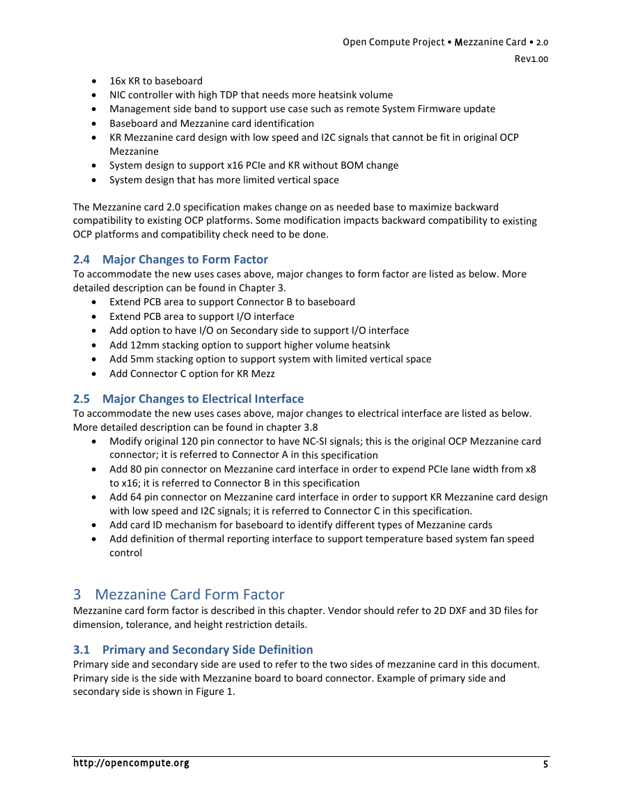
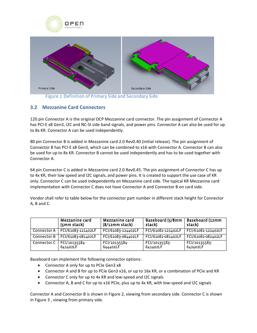
Primary side and secondary side are used to refer to the two sides of mezzanine card in this document.
Primary side is the side with Mezzanine board to board connector. Example of primary side and
secondary side is shown in Figure 1.
http://opencompute.org
5
�
Figure 1: Definition of Primary Side and Secondary Side
3.2 Mezzanine Card Connectors
120 pin Connector A is the original OCP Mezzanine card connector. The pin assignment of Connector A
has PCI‐E x8 Gen3, I2C and NC‐SI side band signals, and power pins. Connector A can also be used for up
to 8x KR. Connector A can be used independently.
80 pin Connector B is added in Mezzanine card 2.0 Rev0.40 (initial release). The pin assignment of
Connector B has PCI‐E x8 Gen3, which can be combined to x16 with Connector A. Connector B can also
be used for up to 8x KR. Connector B cannot be used independently and has to be used together with
Connector A.
64 pin Connector C is added in Mezzanine card 2.0 Rev0.45. The pin assignment of Connector C has up
to 4x KR, their low speed and I2C signals, and power pins. It is created to support the use case of KR
only. Connector C can be used independently on Mezzanine card side. The typical KR Mezzanine card
implementation with Connector C does not have Connector A and Connector B on card side.
Vendor shall refer to table below for the connector part number in different stack height for Connector
A, B and C.
Mezzanine card
(5mm stack)
Connector A FCI/61083-121402LF
Connector B FCI/61083-081402LF
Connector C FCI/10135584-
641402LF
Mezzanine card
(8/12mm stack)
FCI/61083-124402LF
FCI/61083-084402LF
FCI/10135584-
644402LF
Baseboard (5/8mm
stack)
FCI/61082-121402LF
FCI/61082-081402LF
FCI/10135583-
641402LF
Baseboard (12mm
stack)
FCI/61082-122402LF
FCI/61082-082402LF
FCI/10135583-
642402LF
Baseboard can implement the following connector options:
Connector A only for up to PCIe Gen3 x8
Connector A and B for up to PCIe Gen3 x16, or up to 16x KR, or a combination of PCIe and KR
Connector C only for up to 4x KR and low‐speed and I2C signals
Connector A, B and C for up to x16 PCIe, plus up to 4x KR, with low‐speed and I2C signals
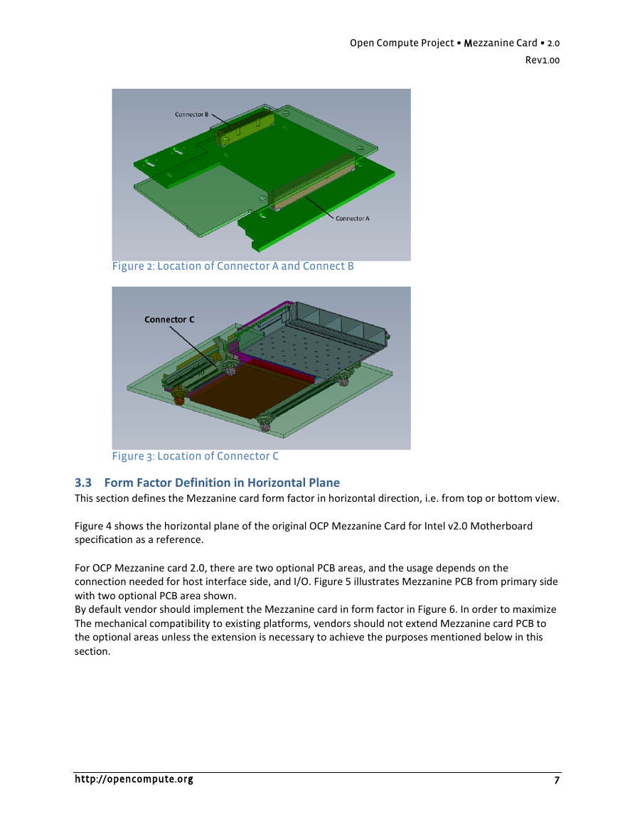
Connector A and Connector B is shown in Figure 2, viewing from secondary side. Connector C is shown
in Figure 3 , viewing from primary side.
�
Open Compute Project Mezzanine Card 2.0
Rev1.00
Figure 2: Location of Connector A and Connect B
Figure 3: Location of Connector C
3.3 Form Factor Definition in Horizontal Plane
This section defines the Mezzanine card form factor in horizontal direction, i.e. from top or bottom view.
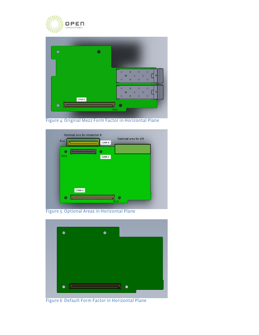
Figure 4 shows the horizontal plane of the original OCP Mezzanine Card for Intel v2.0 Motherboard
specification as a reference.
For OCP Mezzanine card 2.0, there are two optional PCB areas, and the usage depends on the
connection needed for host interface side, and I/O. Figure 5 illustrates Mezzanine PCB from primary side
with two optional PCB area shown.
By default vendor should implement the Mezzanine card in form factor in Figure 6. In order to maximize
The mechanical compatibility to existing platforms, vendors should not extend Mezzanine card PCB to
the optional areas unless the extension is necessary to achieve the purposes mentioned below in this
section.
http://opencompute.org
7
�
Figure 4: Original Mezz Form Factor in Horizontal Plane
Figure 5: Optional Areas in Horizontal Plane
Figure 6: Default Form Factor in Horizontal Plane
�



 2023年江西萍乡中考道德与法治真题及答案.doc
 2012年重庆南川中考生物真题及答案.doc
 2013年江西师范大学地理学综合及文艺理论基础考研真题.doc
 2020年四川甘孜小升初语文真题及答案I卷.doc
 2020年注册岩土工程师专业基础考试真题及答案.doc
 2023-2024学年福建省厦门市九年级上学期数学月考试题及答案.doc
 2021-2022学年辽宁省沈阳市大东区九年级上学期语文期末试题及答案.doc
 2022-2023学年北京东城区初三第一学期物理期末试卷及答案.doc
 2018上半年江西教师资格初中地理学科知识与教学能力真题及答案.doc
 2012年河北国家公务员申论考试真题及答案-省级.doc
 2020-2021学年江苏省扬州市江都区邵樊片九年级上学期数学第一次质量检测试题及答案.doc
 2022下半年黑龙江教师资格证中学综合素质真题及答案.doc