Testing Expo North America 2008
Introduction to Standardized Diagnostic
Communication: UDS on CAN (ISO 15765)
with MVCI (ISO 22900) and ODX (ISO 22901)
Dipl.-Ing. Peter Subke
Key Account Manager
Automotive Electronics
Softing AG, Germany
sub@softing.com
�
Onboard Communication
2
ECU # 1
ECU # 2
Input Info
Output Info
Input Info
Output Info
in-vehicle network (e.g. CAN bus)
onboard communication
ECUs convert input information from sensors to output information
for actuators.
ECUs send information to other ECUs and receice information from
other ECUs (onboard communication).
For onboard communication, ECUs are interconnected via an in-vehicle
network (e.g. CAN)
�
Diagnostic Communication
3
ECU # 1
ECU # 2
Input Info
Output Info
Input Info
Output Info
For diagnostic communication, a TESTER is
connected to the in-vehicle network.
TESTER
The TESTER (client) sends a request to
a specific ECU (e.g. #1) and the ECU
(server) answers the request with a response.
�
Diagnostic Services
4
Diagnostic communication requires a diagnostic protocol.
A diagnostic protocol contains a set of communication parameters and
diagnostic services (request / response).
Typical examples for diagnostic protocols include KWP2000 and UDS.
ISO 14229-1(2006) : Road vehicles –Unified diagnostic services
(UDS) specifies a diagnostic protocol on layer 7 of the OSI model.
Examples for diagnostic services of ISO 14229 include:
11hex = ECU reset
86hex = response on event
19hex = read DTC information
23hex = read memory by address
31hex = routine control
36hex = transfer data
�
UDS on CAN
5
Today, diagnostic communication uses the existing in-vehicle network
to transport requests and responses.
The transport protocol for UDS on CAN is specified in
ISO 15765-3 (2004): Road vehicles –
Diagnostics on controller area network (CAN) –
Part 3: Implementation of unified diagnostic services (UDS on CAN)
ISO 14229-1:2006 (UDS) and ISO 15765-3:2004 (Diagnostics on CAN)
are complementary standards that together specify the diagnostic
protocol “UDS on CAN”.
�
Communication system
6
Tester
Applications (e.g. MONACO, INCA, LabView, AD
Databases (EDF, ODX, FBX,CANdb, A2L)
D-Server (EDIABAS, ETESTER, COS, MVCI)
PC-to-ECU interface software
e.g. EIDBSS, Vecom, D-PDU API
PC-to-ECU interface hardware
e.g. ETK, EDIC, DCDI, VCI
Onboard communication
CAN, LIN, FlexRay, MOST
Diagnostic communication
Diagnostic protocols
KWP 2000, UDS on CAN
UDS on FlexRay
ECU software (e.g. AUTOSAR)
�
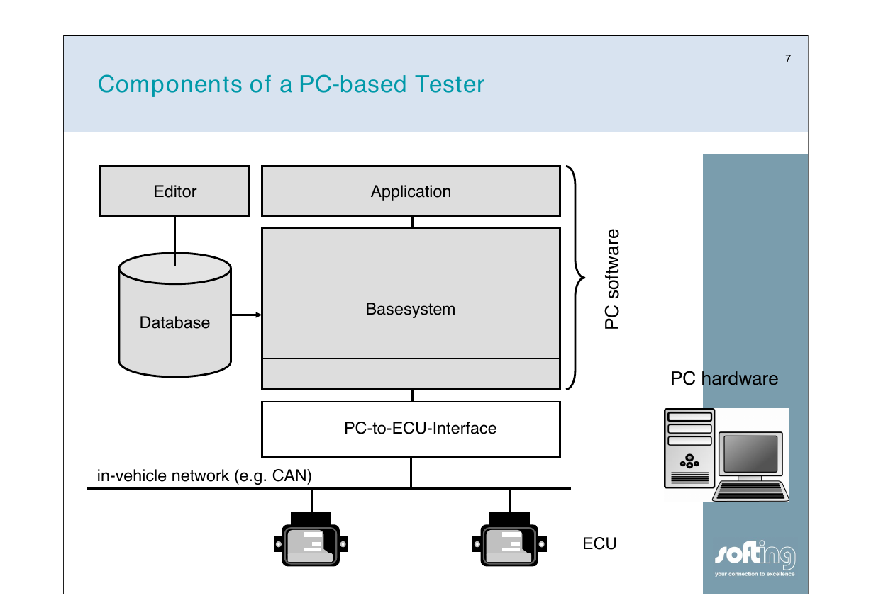
Components of a PC-based Tester
7
Editor
Application
Database
Basesystem
PC-to-ECU-Interface
in-vehicle network (e.g. CAN)
PC hardware
e
r
a
w
t
f
o
s
C
P
ECU
�
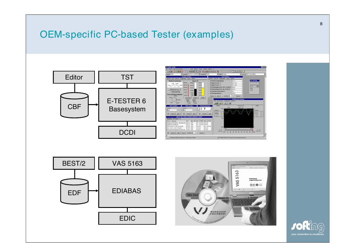
OEM-specific PC-based Tester (examples)
8
Editor
TST
CBF
E-TESTER 6
Basesystem
DCDI
BEST/2
VAS 5163
EDF
EDIABAS
EDIC
�


 2023年江西萍乡中考道德与法治真题及答案.doc
 2012年重庆南川中考生物真题及答案.doc
 2013年江西师范大学地理学综合及文艺理论基础考研真题.doc
 2020年四川甘孜小升初语文真题及答案I卷.doc
 2020年注册岩土工程师专业基础考试真题及答案.doc
 2023-2024学年福建省厦门市九年级上学期数学月考试题及答案.doc
 2021-2022学年辽宁省沈阳市大东区九年级上学期语文期末试题及答案.doc
 2022-2023学年北京东城区初三第一学期物理期末试卷及答案.doc
 2018上半年江西教师资格初中地理学科知识与教学能力真题及答案.doc
 2012年河北国家公务员申论考试真题及答案-省级.doc
 2020-2021学年江苏省扬州市江都区邵樊片九年级上学期数学第一次质量检测试题及答案.doc
 2022下半年黑龙江教师资格证中学综合素质真题及答案.doc