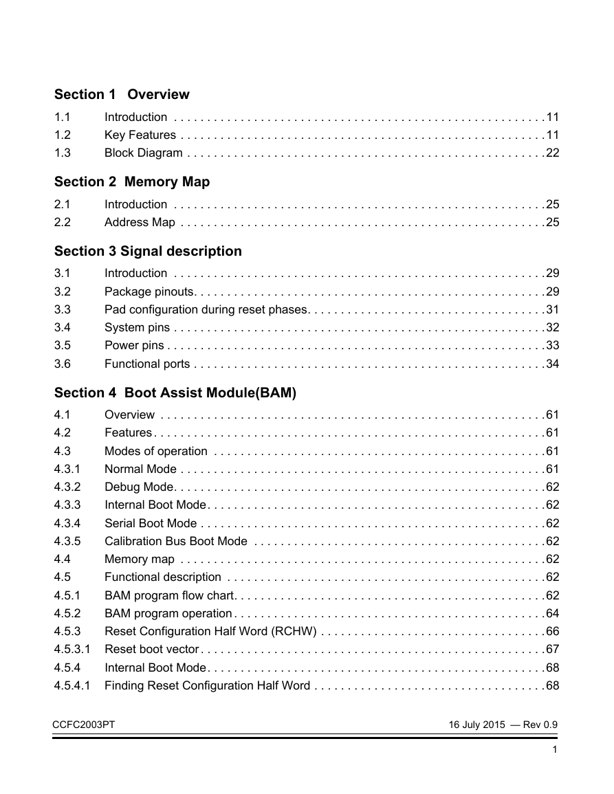
Section 1 Overview
1.1 Introduction
1.2 Key Features
1.3 Block Diagram
Section 2 Memory Map
2.1 Introduction
2.2 Address Map
Section 3 Signal description
3.1 Introduction
3.2 Package pinouts
3.3 Pad configuration during reset phases
3.4 System pins
3.5 Power pins
3.6 Functional ports
Section 4 Boot Assist Module(BAM)
4.1 Overview
4.2 Features
4.3 Modes of operation
4.3.1 Normal Mode
4.3.2 Debug Mode
4.3.3 Internal Boot Mode
4.3.4 Serial Boot Mode
4.3.5 Calibration Bus Boot Mode
4.4 Memory map
4.5 Functional description
4.5.1 BAM program flow chart
4.5.2 BAM program operation
4.5.3 Reset Configuration Half Word (RCHW)
4.5.3.1 Reset boot vector
4.5.4 Internal Boot Mode
4.5.4.1 Finding Reset Configuration Half Word
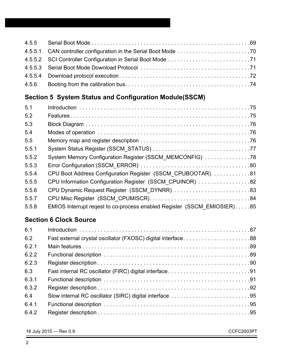
4.5.5 Serial Boot Mode
4.5.5.1 CAN controller configuration in the Serial Boot Mode
4.5.5.2 SCI Controller Configuration in Serial Boot Mode
4.5.5.3 Serial Boot Mode Download Protocol
4.5.5.4 Download protocol execution
4.5.6 Booting from the calibration bus
Section 5 System Status and Configuration Module(SSCM)
5.1 Introduction
5.2 Features
5.3 Block Diagram
5.4 Modes of operation
5.5 Memory map and register description
5.5.1 System Status Register (SSCM_STATUS)
5.5.2 System Memory Configuration Register (SSCM_MEMCONFIG)
5.5.3 Error Configuration (SSCM_ERROR)
5.5.4 CPU Boot Address Configuration Register (SSCM_CPUBOOTAR)
5.5.5 CPU Information Configuration Register (SSCM_CPUINOR)
5.5.6 CPU Dynamic Request Register (SSCM_DYNRR)
5.5.7 CPU Misc Register (SSCM_CPUMISCR)
5.5.8 EMIOS Interrupt reqest to co-process enabled Register (SSCM_EMIOSIER)
Section 6 Clock Source
6.1 Introduction
6.2 Fast external crystal oscillator (FXOSC) digital interface
6.2.1 Main features
6.2.2 Functional description
6.2.3 Register description
6.3 Fast internal RC oscillator (FIRC) digital interface
6.3.1 Functional description
6.3.2 Register description
6.4 Slow internal RC oscillator (SIRC) digital interface
6.4.1 Functional description
6.4.2 Register description
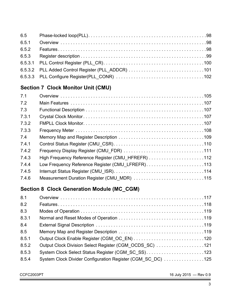
6.5 Phase-locked loop(PLL)
6.5.1 Overview
6.5.2 Features
6.5.3 Register description
6.5.3.1 PLL Control Register (PLL_CR)
6.5.3.2 PLL Added Control Register (PLL_ADDCR)
6.5.3.3 PLL Configure Register(PLL_CONR)
Section 7 Clock Monitor Unit (CMU)
7.1 Overview
7.2 Main Features
7.3 Functional Description
7.3.1 Crystal Clock Monitor
7.3.2 FMPLL Clock Monitor
7.3.3 Frequency Meter
7.4 Memory Map and Register Description
7.4.1 Control Status Register (CMU_CSR)
7.4.2 Frequency Display Register (CMU_FDR)
7.4.3 High Frequency Reference Register (CMU_HFREFR)
7.4.4 Low Frequency Reference Register (CMU_LFREFR)
7.4.5 Interrupt Status Register (CMU_ISR)
7.4.6 Measurement Duration Register (CMU_MDR)
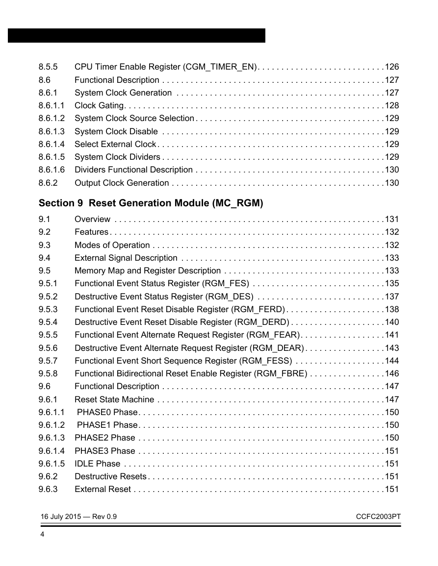
Section 8 Clock Generation Module (MC_CGM)
8.1 Overview
8.2 Features
8.3 Modes of Operation
8.3.1 Normal and Reset Modes of Operation
8.4 External Signal Description
8.5 Memory Map and Register Description
8.5.1 Output Clock Enable Register (CGM_OC_EN)
8.5.2 Output Clock Division Select Register (CGM_OCDS_SC)
8.5.3 System Clock Select Status Register (CGM_SC_SS)
8.5.4 System Clock Divider Configuration Register (CGM_SC_DC)
8.5.5 CPU Timer Enable Register (CGM_TIMER_EN)
8.6 Functional Description
8.6.1 System Clock Generation
8.6.1.1 Clock Gating
8.6.1.2 System Clock Source Selection
8.6.1.3 System Clock Disable
8.6.1.4 Select External Clock
8.6.1.5 System Clock Dividers
8.6.1.6 Dividers Functional Description
8.6.2 Output Clock Generation
Section 9 Reset Generation Module (MC_RGM)
9.1 Overview
9.2 Features
9.3 Modes of Operation
9.4 External Signal Description
9.5 Memory Map and Register Description
9.5.1 Functional Event Status Register (RGM_FES)
9.5.2 Destructive Event Status Register (RGM_DES)
9.5.3 Functional Event Reset Disable Register (RGM_FERD)
9.5.4 Destructive Event Reset Disable Register (RGM_DERD)
9.5.5 Functional Event Alternate Request Register (RGM_FEAR)
9.5.6 Destructive Event Alternate Request Register (RGM_DEAR)
9.5.7 Functional Event Short Sequence Register (RGM_FESS)
9.5.8 Functional Bidirectional Reset Enable Register (RGM_FBRE)
9.6 Functional Description
9.6.1 Reset State Machine
9.6.1.1 PHASE0 Phase
9.6.1.2 PHASE1 Phase
9.6.1.3 PHASE2 Phase
9.6.1.4 PHASE3 Phase
9.6.1.5 IDLE Phase
9.6.2 Destructive Resets
9.6.3 External Reset
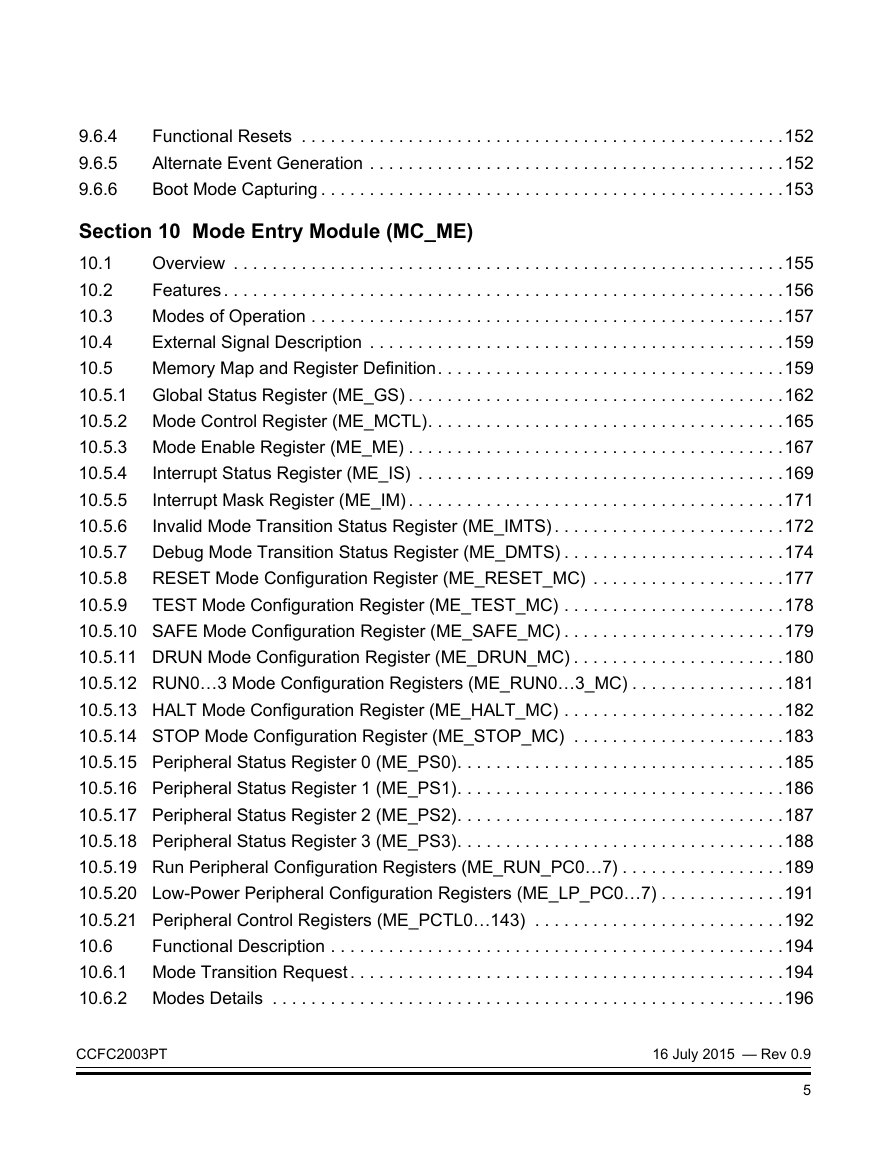
9.6.4 Functional Resets
9.6.5 Alternate Event Generation
9.6.6 Boot Mode Capturing
Section 10 Mode Entry Module (MC_ME)
10.1 Overview
10.2 Features
10.3 Modes of Operation
10.4 External Signal Description
10.5 Memory Map and Register Definition
10.5.1 Global Status Register (ME_GS)
10.5.2 Mode Control Register (ME_MCTL)
10.5.3 Mode Enable Register (ME_ME)
10.5.4 Interrupt Status Register (ME_IS)
10.5.5 Interrupt Mask Register (ME_IM)
10.5.6 Invalid Mode Transition Status Register (ME_IMTS)
10.5.7 Debug Mode Transition Status Register (ME_DMTS)
10.5.8 RESET Mode Configuration Register (ME_RESET_MC)
10.5.9 TEST Mode Configuration Register (ME_TEST_MC)
10.5.10 SAFE Mode Configuration Register (ME_SAFE_MC)
10.5.11 DRUN Mode Configuration Register (ME_DRUN_MC)
10.5.12 RUN0…3 Mode Configuration Registers (ME_RUN0…3_MC)
10.5.13 HALT Mode Configuration Register (ME_HALT_MC)
10.5.14 STOP Mode Configuration Register (ME_STOP_MC)
10.5.15 Peripheral Status Register 0 (ME_PS0)
10.5.16 Peripheral Status Register 1 (ME_PS1)
10.5.17 Peripheral Status Register 2 (ME_PS2)
10.5.18 Peripheral Status Register 3 (ME_PS3)
10.5.19 Run Peripheral Configuration Registers (ME_RUN_PC0…7)
10.5.20 Low-Power Peripheral Configuration Registers (ME_LP_PC0…7)
10.5.21 Peripheral Control Registers (ME_PCTL0…143)
10.6 Functional Description
10.6.1 Mode Transition Request
10.6.2 Modes Details
10.6.2.1 RESET Mode
10.6.2.2 DRUN Mode
10.6.2.3 SAFE Mode
10.6.2.4 TEST Mode
10.6.2.5 RUN0…3 Modes
10.6.2.6 HALT Mode
10.6.2.7 STOP Mode
10.6.3 Mode Transition Process
10.6.3.1 Target Mode Request
10.6.3.2 Target Mode Configuration Loading
10.6.3.3 Peripheral Clocks Disable
10.6.3.4 Processor Low-Power Mode Entry
10.6.3.5 Processor and System Memory Clock Disable
10.6.3.6 Clock Sources Switch-On
10.6.3.7 Main Voltage Regulator Switch-On
10.6.3.8 Flash Modules Switch-On
10.6.3.9 FMPLL Switch-On
10.6.3.10 Power Domain #2 Switch-On
10.6.3.11 Pad Outputs-On
10.6.3.12 Peripheral Clocks Enable
10.6.3.13 Processor and Memory Clock Enable
10.6.3.14 Processor Low-Power Mode Exit
10.6.3.15 System Clock Switching
10.6.3.16 Power Domain #2 Switch-Off
10.6.3.17 Pad Switch-Off
10.6.3.18 FMPLL Switch-Off
10.6.3.19 Clock Sources Switch-Off
10.6.3.20 Flash Switch-Off
10.6.3.21 Main Voltage Regulator Switch-Off
10.6.3.22 Current Mode Update
10.6.4 Protection of Mode Configuration Registers
10.6.5 Mode Transition Interrupts
10.6.5.1 Invalid Mode Configuration Interrupt
10.6.5.2 Invalid Mode Transition Interrupt
10.6.5.3 SAFE Mode Transition Interrupt
10.6.5.4 Mode Transition Complete interrupt
10.6.6 Peripheral Clock Gating
10.6.7 Application Example
Section 11 WKPU
11.1 Introduction
11.2 Features
11.3 External signal description
11.4 Memory map and register description
11.4.1 Memory map
11.4.2 NMI Status Flag Register (NSR)
11.4.3 NMI Configuration Register (NCR)
11.4.4 Wakeup/Interrupt Status Flag Register (WISR)
11.4.5 Interrupt Request Enable Register (IRER)
11.4.6 Wakeup Request Enable Register (WRER)
11.4.7 Wakeup/Interrupt Rising-Edge Event Enable Register (WIREER)
11.4.8 Wakeup/Interrupt Falling-Edge Event Enable Register (WIFEER)
11.4.9 Wakeup/Interrupt Filter Enable Register (WIFER)
11.4.10 Wakeup/Interrupt Pullup Enable Register (WIPUER)
11.5 Functional description
11.5.1 Non-maskable interrupts
11.5.1.1 NMI management
11.5.2 External wakeups/interrupts
11.5.2.1 External interrupt management
11.5.3 On-chip wakeups
11.5.3.1 On-chip wakeup management
Section 12 CAN Sampler
12.1 Introduction
12.2 Features
12.3 Register description
12.3.1 Control Register (CR)
12.3.2 Sample register n (n = 0..11)
12.4 Functional description
12.4.1 Enabling/Disabling the CAN sampler
12.4.2 Baud rate generation
Section 13 C2003 Processor Unit (CPU)
13.1 Introduction
13.2 Features
Section 14 INTC
14.1 Introduction
14.2 Features
14.3 Block Diagram
14.4 Modes of operation
14.4.1 Normal mode
14.4.1.1 Software vector mode
14.4.1.2 Hardware vector mode
14.4.1.3 Debug mode
14.4.1.4 Stop mode
14.5 Memory map and register description
14.5.1 Module memory map
14.5.2 Register description
14.5.2.1 INTC Module Configuration Register (INTC_MCR)
14.5.2.2 INTC Current Priority Register for Processor (INTC_CPR)
14.5.2.3 INTC Interrupt Acknowledge Register (INTC_IACKR)
14.5.2.4 INTC End-of-Interrupt Register (INTC_EOIR)
14.5.2.5 INTC Software Set/Clear Interrupt Registers (INTC_SSCIR0_3–INTC_SSCIR4_7)
14.5.2.6 INTC Priority Select Registers (INTC_PSR0_3–INTC_PSR208_210)
14.6 Functional Description
14.6.1 Interrupt request sources
14.6.1.1 Peripheral interrupt requests
14.6.1.2 Software configurable interrupt requests
14.6.1.3 Unique vector for each interrupt request source
14.6.2 Priority management
14.6.2.1 Current priority and preemption
14.6.2.1.1 Priority arbitrator subblock
14.6.2.1.2 Request selector subblock
14.6.2.1.3 Vector encoder subblock
14.6.2.1.4 Priority Comparator subblock
14.6.2.2 Last-In First-Out (LIFO)
14.6.3 Handshaking with processor
14.6.3.1 Software vector mode handshaking
14.6.3.1.1 Acknowledging interrupt request to processor
14.6.3.1.2 End of interrupt exception handler
14.6.3.2 Hardware vector mode handshaking
14.7 Initialization/application information
14.7.1 Initialization flow
14.7.2 Interrupt exception handler
14.7.2.1 Software vector mode
14.7.2.2 Hardware vector mode
14.7.3 ISR, RTOS, and task hierarchy
14.7.4 Order of execution
14.7.5 Priority ceiling protocol
14.7.5.1 Elevating priority
14.7.5.2 Ensuring coherency
14.7.6 Selecting priorities according to request rates and deadlines
14.7.7 Software configurable interrupt requests
14.7.7.1 Scheduling a lower priority portion of an ISR
14.7.7.2 Scheduling an ISR on another processor
14.7.8 Lowering priority within an ISR
14.7.9 Negating an interrupt request outside of its ISR
14.7.9.1 Negating an interrupt request as a side effect of an ISR
14.7.9.2 Negating multiple interrupt requests in one ISR
14.7.9.3 Proper setting of interrupt request priority
14.7.10 Examining LIFO contents
Section 15 Crossbar Switch (XBAR)
15.1 Introduction
15.2 Main features
15.3 Block diagram
15.4 Modes of operation
15.4.1 Normal mode
15.4.2 Debug mode
15.5 Functional description
15.5.1 Overview
15.5.2 General operation
15.5.3 Master ports
15.5.4 Slave ports
15.5.5 Priority assignment
15.5.6 Arbitration
15.5.6.1 Fixed priority operation
Section 16 LIN Controller (LINFlex)
16.1 Introduction
16.2 Features
16.2.1 LIN mode features
16.2.2 UART mode features
16.2.3 Features common to LIN and UART
16.3 General description
16.4 Fractional baud rate generation
16.5 Operating modes
16.5.1 Initialization mode
16.5.2 Normal mode
16.5.3 Low power mode (Sleep)
16.6 Test modes
16.6.1 Loop Back mode
16.6.2 Self Test mode
16.7 Memory map and registers description
16.7.1 Memory map
16.7.1.1 LIN control register 1 (LINCR1)
16.7.1.2 LIN interrupt enable register (LINIER)
16.7.1.3 LIN status register (LINSR)
16.7.1.4 LIN error status register (LINESR)
16.7.1.5 UART mode control register (UARTCR)
16.7.1.6 UART mode status register (UARTSR)
16.7.1.7 LIN timeout control status register (LINTCSR)
16.7.1.8 LIN output compare register (LINOCR)
16.7.1.9 LIN timeout control register (LINTOCR)
16.7.1.10 LIN fractional baud rate register (LINFBRR)
16.7.1.11 LIN integer baud rate register (LINIBRR)
16.7.1.12 LIN checksum field register (LINCFR)
16.7.1.13 LIN control register 2 (LINCR2)
16.7.1.14 Buffer identifier register (BIDR)
16.7.1.15 Buffer data register LSB (BDRL)
16.7.1.16 Buffer data register MSB (BDRM)
16.7.1.17 Identifier filter enable register (IFER)
16.7.1.18 Identifier filter match index (IFMI)
16.7.1.19 Identifier filter mode register (IFMR)
16.7.1.20 Identifier filter control register (IFCR2n)
16.7.1.21 Identifier filter control register (IFCR2n + 1)
16.8 Functional description
16.8.1 UART mode
16.8.1.1 Buffer in UART mode
16.8.1.2 UART transmitter
16.8.1.3 UART receiver
16.8.1.4 Clock gating
16.8.2 LIN mode
16.8.2.1 Master mode
16.8.2.1.1 LIN header transmission
16.8.2.1.2 Data transmission (transceiver as publisher)
16.8.2.1.3 Data reception (transceiver as subscriber)
16.8.2.1.4 Data discard
16.8.2.1.5 Error detection
16.8.2.1.6 Error handling
16.8.2.2 Slave mode
16.8.2.2.1 Data transmission (transceiver as publisher)
16.8.2.2.2 Data reception (transceiver as subscriber)
16.8.2.2.3 Data discard
16.8.2.2.4 Error detection
16.8.2.2.5 Error handling
16.8.2.2.6 Valid header
16.8.2.2.7 Valid message
16.8.2.2.8 Overrun
16.8.2.3 Slave mode with identifier filtering
16.8.2.3.1 Filter mode
16.8.2.3.2 Identifier filter mode configuration
16.8.2.4 Slave mode with automatic resynchronization
16.8.2.4.1 Deviation error on the Synch Field
16.8.2.5 Clock gating
16.8.3 8-bit timeout counter
16.8.3.1 LIN timeout mode
16.8.3.1.1 LIN Master mode
16.8.3.1.2 LIN Slave mode
16.8.3.2 Output compare mode
16.8.4 Interrupts
Section 17 Deserial Serial Peripheral Interface (DSPI)
17.1 Introduction
17.2 Features
17.3 Modes of operation
17.3.1 Master mode
17.3.2 Slave mode
17.3.3 Module Disable mode
17.3.4 Debug mode
17.4 External signal description
17.4.1 Signal overview
17.4.2 Signal names and descriptions
17.4.2.1 Peripheral Chip Select / Slave Select (CS0_x)
17.4.2.2 Peripheral Chip Selects 1–3 (CS1:3_x)
17.4.2.3 Peripheral Chip Select 4 (CS4_x)
17.4.2.4 Peripheral Chip Select 5 / Peripheral Chip Select Strobe (CS5_x)
17.4.2.5 Serial Input (SIN_x)
17.4.2.6 Serial Output (SOUT_x)
17.4.2.7 Serial Clock (SCK_x)
17.5 Memory map and register description
17.5.1 Memory map
17.5.2 DSPI Module Configuration Register (DSPIx_MCR)
17.5.3 DSPI Transfer Count Register (DSPIx_TCR)
17.5.4 DSPI Clock and Transfer Attributes Registers 0–5 (DSPIx_CTARn)
17.5.5 DSPI Status Register (DSPIx_SR)
17.5.6 DSPI Interrupt Request Enable Register (DSPIx_RSER)
17.5.7 DSPI PUSH TX FIFO Register (DSPIx_PUSHR)
17.5.8 DSPI POP RX FIFO Register (DSPIx_POPR)
17.5.9 DSPI Transmit FIFO Registers 0–3 (DSPIx_TXFRn)
17.5.10 DSPI Receive FIFO Registers 0–3 (DSPIx_RXFRn)
17.6 Functional description
17.6.1 Modes of operation
17.6.1.1 Master mode
17.6.1.2 Slave mode
17.6.1.3 Module Disable mode
17.6.1.4 Debug mode
17.6.2 Start and stop of DSPI transfers
17.6.3 Serial peripheral interface (SPI) configuration
17.6.3.1 SPI Master mode
17.6.3.2 SPI Slave mode
17.6.3.3 FIFO disable operation
17.6.3.4 Transmit First In First Out (TX FIFO) buffering mechanism
17.6.3.4.1 Filling the TX FIFO
17.6.3.4.2 Draining the TX FIFO
17.6.3.5 Receive First In First Out (RX FIFO) buffering mechanism
17.6.3.5.1 Filling the RX FIFO
17.6.3.5.2 Draining the RX FIFO
17.6.4 DSPI baud rate and clock delay generation
17.6.4.1 Baud rate generator
17.6.4.2 CS to SCK delay (tCSC)
17.6.4.3 After SCK delay (tASC)
17.6.4.4 Delay after transfer (tDT)
17.6.4.5 Peripheral chip select strobe enable (CS5_x)
17.6.5 Transfer formats
17.6.5.1 Classic SPI transfer format (CPHA = 0)
17.6.5.2 Classic SPI transfer format (CPHA = 1)
17.6.5.3 Modified SPI transfer format (MTFE = 1, CPHA = 0)
17.6.5.4 Modified SPI transfer format (MTFE = 1, CPHA = 1)
17.6.5.5 Continuous selection format
17.6.5.6 Clock polarity switching between DSPI transfers
17.6.6 Continuous serial communications clock
17.6.7 Interrupt requests
17.6.7.1 End of Queue Interrupt Request (EOQF)
17.6.7.2 Transmit FIFO Fill Interrupt Request (TFFF)
17.6.7.3 Transfer Complete Interrupt Request (TCF)
17.6.7.4 Receive FIFO Drain Interrupt Request (RFDF)
17.6.7.5 Receive FIFO Overflow Interrupt Request (RFOF)
17.6.7.6 FIFO Overrun Request (TFUF) or (RFOF)
17.6.8 Power saving features
17.6.8.1 Module Disable mode
17.6.8.2 Slave interface signal gating
17.7 Initialization and application information
17.7.1 How to change queues
17.7.2 Baud rate settings
17.7.3 Delay settings
17.7.4 Calculation of FIFO pointer addresses
17.7.4.1 Address calculation for the first-in entry and last-in entry in the TX FIFO
17.7.4.2 Address calculation for the first-in entry and last-in entry in the RX FIFO
Section 18 Inter-Integrated Circuit Bus Controller Module (I2C)
18.1 Introduction
18.1.1 Overview
18.1.2 Features
18.1.3 Block Diagram
18.2 External Signal Description
18.2.1 SCL
18.2.2 SDA
18.3 Memory map and register description
18.3.1 Module memory map
18.3.2 Slave Address Register (I2CSA)
18.3.3 I2C Control Register (I2CC)
18.3.4 I2C Clock Prescalar Register (I2CP)
18.3.5 I2C Status Register(I2CS)
18.3.6 I2C Data Register(I2CD)
18.3.7 I2C slave SDA hold time register(I2CSHT)
18.3.8 I2C slave high-speed mode indicator register(I2CSHIR)
18.3.9 I2C fifo status configure register(I2CFIFOSR)
18.3.10 I2C illegal Start and Stop status register(I2CILLER)
18.3.11 I2C Slave Hold time register(I2CSLHTR)
18.4 Function description
18.4.1 Master Mode
18.4.2 Slave Mode
18.4.3 Protocol
18.4.4 Arbitration Procedure
18.4.5 Clock Synchronization
18.4.6 Handshaking
18.4.7 Clock Stretching
18.4.8 High-Speed Mode operation
18.4.9 High-Speed Mode operation
Section 19 Controller Area Network(FLEXCAN)
19.1 Introduction
19.1.1 Overview
19.1.2 FlexCAN module features
19.1.3 Modes of operation
19.2 External signal description
19.2.1 Overview
19.2.2 Signal descriptions
19.2.2.1 CAN Rx
19.2.2.2 CAN Tx
19.3 Memory map and register description
19.3.1 FlexCAN memory mapping
19.3.2 Message buffer structure
19.3.3 Rx FIFO structure
19.3.4 Register description
19.3.4.1 Module Configuration Register (MCR)
19.3.4.2 Control Register (CTRL)
19.3.4.3 Free Running Timer (TIMER)
19.3.4.4 Rx Global Mask (RXGMASK)
19.3.4.5 Rx 14 Mask (RX14MASK)
19.3.4.6 Rx 15 Mask (RX15MASK)
19.3.4.7 Error Counter Register (ECR)
19.3.4.8 Error and Status Register (ESR)
19.3.4.9 Interrupt Masks 2 Register (IMASK2)
19.3.4.10 Interrupt Masks 1 Register (IMASK1)
19.3.4.11 Interrupt Flags 2 Register (IFLAG2)
19.3.4.12 Interrupt Flags 1 Register (IFLAG1)
19.3.4.13 Rx Individual Mask Registers (RXIMR0–RXIMR63)
19.4 Functional description
19.4.1 Overview
19.4.2 Local priority transmission
19.4.3 Transmit process
19.4.4 Arbitration process
19.4.5 Receive process
19.4.6 Matching process
19.4.7 Data coherence
19.4.7.1 Transmission abort mechanism
19.4.7.2 Message buffer deactivation
19.4.7.3 Message buffer lock mechanism
19.4.8 Rx FIFO
19.4.9 CAN protocol related features
19.4.9.1 Remote frames
19.4.9.2 Overload frames
19.4.9.3 Time stamp
19.4.9.4 Protocol timing
19.4.9.5 Arbitration and matching timing
19.4.10 Modes of operation details
19.4.10.1 Freeze Mode
19.4.10.2 Module Disable Mode
19.4.11 Interrupts
19.4.11.1 Bus interface
19.5 Initialization/Application information
19.5.1 FlexCAN initialization sequence
19.5.2 FlexCAN addressing and SRAM size configurations
Section 20 Periodic Interrupt Timer (PIT)
20.1 Introduction
20.2 Features
20.3 Signal description
20.4 Memory map and register description
20.4.1 Memory map
20.4.2 PIT Module Control Register (PITMCR)
20.4.3 Timer Load Value Register (LDVAL)
20.4.4 Current Timer Value Register (CVAL)
20.4.5 Timer Control Register (TCTRL)
20.4.6 Timer Flag Register (TFLG)
20.5 Functional description
20.5.1 General
20.5.1.1 Timers
20.5.1.2 Debug mode
20.5.1.3 Interrupts
20.5.2 Initialization and application information
20.5.2.1 Example configuration
Section 21 Enhanced Modular IO Subsystem (eMIOS)
21.1 Introduction
21.1.1 Features of the eMIOS module
21.1.2 Modes of operation
21.1.3 Channel implementation
21.1.4 Channel mode selection
21.2 External signal description
21.3 Memory map and register description
21.3.1 Memory maps
21.3.2 Unified Channel memory map
21.3.3 Register description
21.3.3.1 eMIOS Module Configuration Register (EMIOSMCR)
21.3.3.2 eMIOS Global FLAG (EMIOSGFLAG) Register
21.3.3.3 eMIOS Output Update Disable (EMIOSOUDIS) Register
21.3.3.4 eMIOS Disable Channel (EMIOSUCDIS) Registe
21.3.3.5 eMIOS UC A Register (EMIOSA[n])
21.3.3.6 eMIOS UC B Register (EMIOSB[n])
21.3.3.7 eMIOS UC Counter Register (EMIOSCNT[n])
21.3.3.8 eMIOS UC Control Register (EMIOSC[n])
21.3.3.9 eMIOS UC Status Register (EMIOSS[n])
21.3.3.10 eMIOS UC Alternate A Register (EMIOSALTA[n])
21.4 Functional description
21.4.1 Unified Channel (UC)
21.4.1.1 UC modes of operation
21.4.1.2 General purpose Input/Output (GPIO) mode
21.4.1.3 Single Action Input Capture (SAIC) mode
21.4.1.4 Single Action Output Compare (SAOC) mode
21.4.1.5 Input Pulse Width Measurement (IPWM) Mode
21.4.1.6 Input Period Measurement (IPM) mode
21.4.1.7 Double Action Output Compare (DAOC) mode
21.4.1.8 Modulus Counter (MC) mode
21.4.1.9 Modulus Counter Buffered (MCB) mode
21.4.1.10 Output Pulse Width and Frequency Modulation Buffered (OPWFMB) mode
21.4.1.11 Center Aligned Output PWM Buffered with Dead-Time (OPWMCB) mode
21.4.1.12 Output Pulse Width Modulation Buffered (OPWMB) Mode
21.4.1.13 Output Pulse Width Modulation with Trigger (OPWMT) mode
21.4.1.14 Input Programmable Filter (IPF)
21.4.1.15 Clock Prescaler (CP)
21.4.1.16 Effect of Freeze on the Unified Channel
21.4.2 IP Bus Interface Unit (BIU)
21.4.2.1 Effect of Freeze on the BIU
21.4.3 Global Clock Prescaler Submodule (GCP)
21.4.3.1 Effect of Freeze on the GCP
21.5 Initialization/Application information
21.5.1 Considerations
21.5.2 Application information
21.5.2.1 Time base generation
21.5.2.2 Coherent accesses
21.5.2.3 Channel/Modes initialization
Section 22 System Timer Module (STM)
22.1 Introduction
22.2 Features
22.3 Modes of operation
22.4 Memory map and register description
22.4.1 Memory map
22.4.2 Register descriptions
22.4.2.1 STM Control Register (STM_CR)
22.4.2.2 STM Count Register (STM_CNT)
22.4.2.3 STM Channel Control Register (STM_CCRn)
22.4.2.4 STM Channel Interrupt Register (STM_CIRn)
22.4.2.5 STM Channel Compare Register (STM_CMPn)
22.5 Functional description
Section 23 Decimation Filter Introduction
23.1 Information specific to this device
23.1.1 Device-specific features
23.2 Introduction
23.2.1 Overview
23.2.2 Features
23.2.3 Modes of operation
23.2.3.1 Normal Mode
23.2.3.2 Standalone Mode
23.2.3.3 Low Power Mode
23.2.3.4 Freeze Mode
23.3 External signal description
23.3.1 Decimation trigger signal
23.4 Memory map and register definition
23.4.1 Decimation filter device memory map
23.4.2 Decimation filter register descriptions
23.4.2.1 Decimation Filter Module Configuration Register (DECFILTER_MCR)
23.4.2.2 Decimation Filter Module Status Register (DECFILTER_MSR)
23.4.2.3 Decimation Filter Interface Input Buffer Register (DECFILTER_IB)
23.4.2.4 Decimation Filter Interface Output Buffer Register (DECFILTER_OB)
23.4.2.5 Decimation Filter Coefficient n Register (DzzECFILTER_COEFn)
23.4.2.6 Decimation Filter TAPn Register (DECFILTER_TAPn)
23.4.2.7 Decimation Filter Interface Enhanced Debug Input Data Register (DECFILTER_EDID)
23.4.3 Decimation filter memory map for parallel side interface
23.4.4 PSI register description
23.4.4.1 Decimation Filter Input/Output Buffers Register (DECFILTER_IOB)
23.5 Functional description
23.5.1 Overview
23.5.2 Parallel Side Interface (PSI) description
23.5.3 Input buffer description
23.5.3.1 Input buffer overrun
23.5.4 Output buffer description
23.5.4.1 Output buffer overrun
23.5.4.2 Triggered output result description
23.5.5 Bypass configuration description
23.5.6 IIR and FIR filter
23.5.6.1 Rounding
23.5.6.2 Saturation
23.5.7 Filter prefill control description
23.5.8 Timestamp data transmission
23.5.9 Flush Command description
23.5.10 Soft-Reset command description
23.5.11 nterrupts requests description
23.5.11.1 Block interrupt request
23.5.11.2 Input buffer interrupt request
23.5.11.3 Output buffer interrupt request
23.5.12 DMA requests description
23.5.12.1 Input buffer DMA request
23.5.12.2 Output buffer DMA request
23.5.13 Freeze Mode description
23.5.14 Enhanced Debug Monitor description
23.6 Initialization information
23.6.1 Initialization procedure
23.7 Application information
23.7.1 eQADC IP as the master block
23.8 Filter example simulation
23.8.1 Coefficients calculation
23.8.2 Input data calculation
23.8.3 Filter results
Section 24 eQADC
24.1 Information specific to this device
24.1.1 Device-specific features
24.1.2 Device-specific pin configuration features
24.1.2.1 ATRIG0 — Advanced Trigger
24.1.2.2 ETRIG0–ETRIG5 — External Triggers
24.2 Introduction
24.2.1 Module overview
24.2.2 Block diagram
24.2.3 Features
24.3 Modes of operation
24.3.1 Normal Mode
24.3.2 Debug Mode
24.3.3 Stop Mode
24.4 External signal description
24.4.1 Overview
24.4.2 Detailed signal descriptions
24.4.2.1 AN0/DAN0+ — Single-ended analog input/Differential analog input positive terminal
24.4.2.2 AN1/DAN0 — Single-ended analog input/Differential analog input negative terminal
24.4.2.3 AN2/DAN1+ — Single-ended analog input/Differential analog input positive terminal
24.4.2.4 AN3/DAN1 — Single-ended analog input/Differential analog input negative terminal
24.4.2.5 AN4/DAN2 — Single-ended analog input/Differential analog input positive terminal
24.4.2.6 AN5/DAN2 — Single-ended analog input/Differential analog input negative terminal
24.4.2.7 AN6/DAN3+ — Single-ended analog input/Differential analog input positive terminal
24.4.2.8 AN7/DAN3 — Single-ended analog input/Differential analog input negative terminal
24.4.2.9 AN8/ANW — Single-ended analog input/Single-ended analog input from external multiplexers
24.4.2.10 AN9/ANX — Single-ended analog input/Single-ended analog input from external multiplexers
24.4.2.11 AN10/ANY — Single-ended analog input/Single-ended analog input from external multiplexers
24.4.2.12 AN11/ANZ — Single-ended analog input/Single-ended analog input from external multiplexers
24.4.2.13 AN12 — Single-ended analog input
24.4.2.14 AN13F — Single-ended analog input
24.4.2.15 AN14 — Single-ended analog input
24.4.2.16 AN15 — Single-ended analog input
24.4.2.17 AN16/ANR — Single-ended analog input/Single-ended analog input from external multiplexers
24.4.2.18 AN17/ANS — Single-ended analog input/Single-ended analog input from external multiplexers
24.4.2.19 AN18/ANT — Single-ended analog input/Single-ended analog input from external multiplexers
24.4.2.20 AN19/ANU — Single-ended analog input/Single-ended analog input from external multiplexers
24.4.2.21 AN20–AN39 — Single-ended analog input
24.4.2.22 MA0–MA2 — External multiplexer control signals
24.4.2.23 VDDA, VSSA — 5V VDD and VSS for the 5V analog components
24.4.2.24 ATRIG0 — Advanced triggers
24.4.2.25 ETRIG0–ETRIG5 — External triggers
24.5 Memory map/register definition
24.5.1 eQADC memory map
24.5.2 eQADC register descriptions
24.5.2.1 eQADC Module Configuration Register (EQADC_MCR)
24.5.2.2 eQADC Null Message Send Format Register (EQADC_NMSFR)
24.5.2.3 eQADC External Trigger Digital Filter Register (EQADC_ETDFR)
24.5.2.4 eQADC CFIFO Push Registers (EQADC_CFPR)
24.5.2.5 eQADC Result FIFO Pop Registers (EQADC_RFPR)
24.5.2.6 eQADC CFIFO Control Registers (EQADC_CFCR)
24.5.2.7 eQADC Interrupt and DMA Control Registers (EQADC_IDCR)
24.5.2.8 eQADC FIFO and Interrupt Status Registers (EQADC_FISR)
24.5.2.9 eQADC CFIFO Transfer Counter Registers (EQADC_CFTCR)
24.5.2.10 eQADC CFIFO Status Snapshot Registers (EQADC_CFSSR)
24.5.2.11 eQADC CFIFO Status Register (EQADC_CFSR)
24.5.2.12 eQADC CFIFO Registers (EQADC_CFxRw) (x = 0, ..,5; w = 0, .., 3)
24.5.2.13 eQADC CFIFO0 Extension Registers (EQADC_CF0ERw) (w = 0, .., 3)
24.5.2.14 eQADC RFIFO Registers (EQADC_RFxRw) (x = 0, .., 5; w = 0, .., 3)
24.5.3 On-chip ADC registers
24.5.3.1 ADC0/1 Control Registers (ADC0_CR and ADC1_CR)
24.5.3.2 ADC Time Stamp Control Register (ADC_TSCR)
24.5.3.3 ADC Time Base Counter Registers (ADC_TBCR)
24.5.3.4 Alternate Configuration 1–8 Control Registers (ADC_ACR1–8)
24.6 Functional description
24.6.1 Overview
24.6.2 Data flow in eQADC
24.6.2.1 Overview and basic terminology
24.6.2.2 Assumptions/Requirements regarding the external device
24.6.2.2.1 Number of command buffers and result buffers
24.6.2.2.2 Command execution and result return
24.6.2.2.3 Null and result messages
24.6.2.3 Message format in eQADC
24.6.2.3.1 Message formats for on-chip ADC operation
24.6.2.3.2 Message formats for external device operation
24.6.3 Command/Result queues
24.6.4 eQADC command FIFOs
24.6.4.1 CFIFO basic functionality
24.6.4.2 CFIFO0 streaming mode description
24.6.4.2.1 CFIFO0 operation in streaming mode
24.6.4.2.2 Triggering description in streaming mode
24.6.4.2.3 CFIFO0 diagram description in streaming mode
24.6.4.2.4 Streaming mode error conditions
24.6.4.3 CFIFO common prioritization and command transfer
24.6.4.4 CFIFO prioritization in abort mode
24.6.4.5 External trigger event detection
24.6.4.6 CFIFO scan trigger modes
24.6.4.6.1 Disabled Mode
24.6.4.6.2 Single-scan Mode
24.6.4.7 CFIFO and trigger status
24.6.4.7.1 CFIFO operation status
24.6.4.7.2 CQueue completion status
24.6.4.7.3 Pause status
24.6.4.7.4 Trigger overrun status
24.6.4.7.5 Command sequence non-coherency detection
24.6.5 eQADC result FIFOs
24.6.5.1 RFIFO basic functionality
24.6.5.2 Distributing result data into RFIFOs
24.6.6 On-chip ADC configuration and control
24.6.6.1 Enabling and disabling the on-chip ADCs
24.6.6.2 ADC clock and conversion speed
24.6.6.3 Time stamp feature
24.6.6.3.1 STAC client submodule (REDLC)
24.6.6.4 ADC pre-gain feature
24.6.6.4.1 ADC resolution selection feature
24.6.6.5 ADC Control Logic overview and command execution
24.6.7 Internal/External multiplexing
24.6.7.1 Channel assignment
24.6.8 eQADC DMA/Interrupt request
24.6.9 eQADC parallel side interface (PSI) sub-block
24.6.9.1 Input/Output signals description
24.6.9.2 PSI transmitter / write section
24.6.9.3 PSI receiver / read section
24.7 Initialization/Application information
24.7.1 Multiple queues control setup example
24.7.1.1 eQADC initialization
24.7.1.2 Configuring eQADC for applications
24.7.2 eQADC/DMAC interface
24.7.2.1 CQueue/CFIFO transfers
24.7.2.2 RQueue/RFIFO transfers
24.7.3 Sending immediate command setup example
24.7.4 Modifying queues
24.7.5 CQueue and RQueues usage
Section 25 Software Watchdog Timer (SWT)
25.1 Introduction
25.2 Features
25.3 Modes of operation
25.4 External signal description
25.5 Memory map and register description
25.5.1 Memory map
25.5.2 Register description
25.5.2.1 SWT Control Register (SWT_CR)
25.5.2.2 SWT Interrupt Register (SWT_IR)
25.5.2.3 SWT Time-Out Register (SWT_TO)
25.5.2.4 SWT Window Register (SWT_WN)
25.5.2.5 SWT Service Register (SWT_SR)
25.5.2.6 SWT Counter Output Register (SWT_CO)
25.6 Functional description
Section 26 Error Correction Status Module (ECSM)
26.1 Introduction
26.2 Overview
26.3 Features
26.4 Memory map and register description
26.4.1 Memory map
26.4.2 Register description
26.4.2.1 Processor Core Type Register (PCT)
26.4.2.2 SoC-Defined Platform Revision Register (REV)
26.4.2.3 IPS On-Platform Module Configuration Register (IOPMC)
26.4.2.4 ECC registers
26.4.2.4.1 ECC Configuration Register (ECR)
26.4.2.4.2 ECC Status Register (ESR)
26.4.2.4.3 ECC Error Generation Register (EEGR)
26.4.2.4.4 Platform Flash ECC Address Register (PFEAR)
26.4.2.4.5 Platform Flash ECC Master Number Register (PFEMR)
26.4.2.4.6 Platform Flash ECC Attributes Register (PFEAT)
26.4.2.4.7 Platform Flash ECC Data Register (PFEDR)
26.4.2.4.8 Platform RAM ECC Address Register (PREAR)
26.4.2.4.9 Platform RAM ECC Syndrome Register (PRESR)
26.4.2.4.10 Platform RAM ECC Master Number Register (PREMR)
26.4.2.4.11 Platform RAM ECC Attributes Register (PREAT)
26.4.2.4.12 Platform RAM ECC Data Register (PREDR)
26.4.3 Register protection
Section 27 Flash Memory
27.1 Overview
27.2 Platform flash memory controller(PFLASH_LCA)
27.2.1 Overview
27.2.2 Main features
27.2.3 Detailed description
27.2.3.1 Basic interface protocol
27.2.3.2 Access protections
27.2.3.3 Read cycles - Buffer miss
27.2.3.4 Read cycles - Buffer hit
27.2.3.5 Error termination
27.2.3.6 Access pipelining
27.2.3.7 Flash error response operation
27.2.3.8 Bank page read buffers
27.2.3.8.1 Buffer Invalidation
27.3 Flash memory block
27.3.1 Flash block overview
27.3.2 LC flash features
27.3.3 Programming considerations
27.3.3.1 Modify operations
27.3.3.1.2 Block Erase
27.3.3.1.3 Erase Suspend/Resume
27.3.3.2 Error correction code
27.3.3.2.1 ECC algorithms
27.3.3.3 EEPROM emulation
27.3.3.3.1 All ’1’s No Error
27.3.3.4 Protection strategy
27.3.3.4.1 Modify protection
27.3.3.4.2 Censored mode
27.4 Memory maps
27.4.1 Overview memory map
27.4.2 Flash memory space map
27.4.3 Test block
27.4.3.1 Test block memory map
27.4.3.2 Unique serial number
27.4.3.3 RDN High/Low Information
27.4.4 Shadow sector
27.4.5 Flash control and configuration registers map
27.5 Register desciptions
27.5.1 Flash control and configuration registers
27.5.1.1 Flash Controller (PFLASH_LCA) Registers
27.5.1.1.1 Platform Flash Configuration Register 0 (PFCR0)
27.5.1.1.2 Platform Flash Access Protection Register (PFAPR)
27.5.1.1.3 Platform Flash Configuration Register 1 (PFCR1)
27.5.1.2 Flash array module registers
27.5.1.2.1 Module Configuration Register (MCR)
27.5.1.2.2 Low/Mid Address Space Block Locking Register (LMLR)
27.5.1.2.3 High Address Space Block Locking Register (HLR)
27.5.1.2.4 Secondary Low/Mid Address Space Block Lock Register (SLMLR)
27.5.1.2.5 Low/Mid Address Space Block Select Register (LMSR)
27.5.1.2.6 High Address Space Block Select Register (HSR)
27.5.1.2.7 Address Register (AR)
27.5.1.2.8 Module Configuration Register for God(GOD_MCR)
27.5.1.2.9 Erase Address Register (EAR)
27.5.1.2.10 Fatal Error Counter Register(FECR)
27.5.1.2.11 Flash Program and Erase Timing Adjuestment Register 0(FLASH_PETAR0)
27.5.1.2.12 Flash Program and Erase Timing Adjuestment Register 1(FLASH_PETAR1)
27.5.1.2.13 Flash Program and Erase Timing Adjuestment Register 2(FLASH_PETAR2)
27.5.1.2.14 RDN Information Register0(RDNINFO0)
27.5.1.2.15 RDN Information Register1(RDNINFO1)
Section 28 SIUL
28.1 Introduction
28.2 Feature List
28.3 Function Description
28.3.1 Pad Control
28.3.2 GPIO
28.3.3 External Interrupts
28.4 Memory Map and Registers
28.4.1 MCU ID Reg 2 (MIDR2)
28.4.2 MCU ID Reg (MIDR)
28.4.3 SIUL Reset Status Register (SIU_RSR)
28.4.4 Interrupt Status Flag Register (ISR)
28.4.5 Interrupt Request Enable Register (IRER)
28.4.6 Interrupt Rising-edge Event Enable Register (IREER)
28.4.7 Interrupt Falling-edge Event Enable Register (IFEER)
28.4.8 Interrupt Filter Enable Register (IFER)
28.4.9 Pad Configuration Registers (PCR0~138)
28.4.10 Pad Selection for Multiplexed Inputs Registers (PSMI0_3~PSMI28_31)
28.4.11 GPIO Pad Data Output Registers (GPDO0_3~136_139)
28.4.12 GPIO Pad Data Input Registers (GPDI0_3~136_139)
28.4.13 Parallel GPIO Pad Data Out Registers (PGPDO0~4)
28.4.14 eQADC Trigger Input Select Register (SIU_ETISR)
28.4.15 EQADC Trigger IMUX Select Register 0-5 (SIU_ETSEL0-5)
28.4.16 EQADC Trigger IMUX Select Register a (SIU_ETSELa)
28.4.17 PIT Trigger IMUX Select Register (SIU_PTISEL)
28.4.18 Local Select Register (SIU_LSR)
28.4.19 External Trigger Filter Enable Register(SIU_ETFER)
28.4.20 SIUL Chip Configuration Register (SIU_CCR)
28.4.21 Parallel GPIO Pad Data In Registers (PGPDI0~4)
28.4.22 Masked Parallel GPIO Pad Data Out Register (MPGPDO0~8)
28.4.23 Interrupt Filter Maximum Counter Registers (IFMC0~15)
28.4.24 Interrupt Filter Clock Prescaler Register (IFCPR)
Section 29 Direct Memory Access
29.1 Introduction
29.2 Channel assignments
29.3 Features
29.4 Memory map and Register Description
29.4.1 Register descriptions
29.4.1.1 DMA Control Register (DMA_CR)
29.4.1.2 DMA Error Status Register (DMA_ESR)
29.4.1.3 DMA Bus Error Address Register
29.4.1.4 DMA Enable Request Register (DMA_ERQRL)
29.4.1.5 DMA Enable Error Interrupt Register (DMA_EEIRL)
29.4.1.6 DMA Set Enable Request Register (DMA_SERQR)
29.4.1.7 DMA Clear Enable Request Register (DMA_CERQR)
29.4.1.8 DMA Set Enable Error Interrupt Register (DMA_SEEIR)
29.4.1.9 DMA Clear Enable Error Interrupt Register (DMA_CEEIR)
29.4.1.10 DMA Clear Interrupt Request Register (DMA_CIRQR)
29.4.1.11 DMA Clear Error Register (DMA_CER)
29.4.1.12 DMA Set START Bit Register (DMA_SSBR)
29.4.1.13 DMA Clear DONE Status Bit Register (DMA_CDSBR)
29.4.1.14 DMA Interrupt Request (DMA_IRQRL)
29.4.1.15 DMA Error (DMA_ERL) Register
29.4.1.16 DMA Channel n Priority (DCHPRIn), n = 0,...,31
29.4.1.17 Transfer Control Descriptor (TCD)
29.5 Functional Description
29.5.1 DMA microarchitecture
29.5.2 DMA basic data flow
29.6 Initialization/application information
29.6.1 DMA initialization
29.6.2 DMA programming errors
29.6.3 DMA arbitration mode considerations
29.6.3.1 Fixed group arbitration, fixed channel arbitration
29.6.3.2 Round-robin group arbitration, fixed channel arbitration
29.6.3.3 Round-robin group arbitration, round-robin channel arbitration
29.6.3.4 Fixed group arbitration, round-robin channel arbitration
29.6.4 DMA transfer
29.6.4.1 Single request
29.6.4.2 Multiple requests
29.6.5 TCD status
29.6.5.1 Minor loop complete
29.6.5.2 Active channel TCD reads
29.6.5.3 Preemption status
29.6.6 Channel linking
29.6.7 Dynamic programming
29.6.7.1 Dynamic priority changing
29.6.7.2 Dynamic channel linking and dynamic scatter/gather
Section 30 External Bus Interface for Calibration Bus
30.1 Introduction
30.2 Features
30.3 Memory map and Register Description
30.3.1 Register descriptions
30.3.1.1 Chip Select Control Registers
30.3.1.1.1 Chip Select Control Registers 0
30.3.1.1.2 Chip Select Control Registers 1
30.4 EBI Functional Description
30.4.1 EB Signal Timing
30.4.2 Chip Selects
30.4.3 Operand Transfer
30.4.4 Enable Byte Pins(eb[3:0])
Section 31 Register Protection
31.1 Introduction
31.2 Features
31.3 Modes of operation
31.4 External signal description
31.5 Memory map and register description
31.5.1 Memory map
31.5.2 Register description
31.5.2.1 Module Registers (MR0-6143)
31.5.2.2 Module Register and Set Soft Lock Bit (LMR0-6143)
31.5.2.3 Soft Lock Bit Register (SLBR0-1535)
31.5.2.4 Global Configuration Register (GCR)
31.6 Functional description
31.6.1 General
31.6.2 Change lock settings
31.6.2.1 Change lock settings directly via area #4
31.6.2.2 Enable locking via mirror module space (area #3)
31.6.2.3 Write protection for locking bits
31.6.3 Access errors
31.7 Reset
31.8 Protected registers
Appendix A Preliminary Electrical Characteristic
A.1 General
A.2 Absolute Maximum Ratings
A.3 Electrostatic Discharge (ESD) Protection
A.4 Fast internal RC oscillator (16 MHz) electrical characteristics
A.5 Voltage Reference Electrical Characteristics
A.6 Power Management Electrical Characteristics
A.6.1 PMU Electrical Characteristics
A.6.2 Power-Up Sequence
A.6.3 Power-Down Sequence
A.7 ADC Electrical Characteristics
A.8 I/O pad electrical characteristics
A.8.1 I/O input DC characteristics
A.8.2 I/O output DC characteristics
A.8.3 PAD AC Specifications
A.9 FMPLL Electrical Characteristics
A.9.1 FMPLL electrical characteristics
A.10 AC timing
A.10.1 IEEE 1149.1 interface timing
A.10.2 DSPI AC timing
A.10.3 eMIOS timing
A.10.4 CLKOUT timing
Appendix B Mechanical Specifications
B.1 General
B.2 LQFP208 Mechanical Drawing



 2023年江西萍乡中考道德与法治真题及答案.doc
 2012年重庆南川中考生物真题及答案.doc
 2013年江西师范大学地理学综合及文艺理论基础考研真题.doc
 2020年四川甘孜小升初语文真题及答案I卷.doc
 2020年注册岩土工程师专业基础考试真题及答案.doc
 2023-2024学年福建省厦门市九年级上学期数学月考试题及答案.doc
 2021-2022学年辽宁省沈阳市大东区九年级上学期语文期末试题及答案.doc
 2022-2023学年北京东城区初三第一学期物理期末试卷及答案.doc
 2018上半年江西教师资格初中地理学科知识与教学能力真题及答案.doc
 2012年河北国家公务员申论考试真题及答案-省级.doc
 2020-2021学年江苏省扬州市江都区邵樊片九年级上学期数学第一次质量检测试题及答案.doc
 2022下半年黑龙江教师资格证中学综合素质真题及答案.doc