logo资料库

摩托罗拉单片机MC68HC908MR32教程.pdf

第1页 / 共384页
第2页 / 共384页
第3页 / 共384页
第4页 / 共384页
第5页 / 共384页
第6页 / 共384页
第7页 / 共384页
第8页 / 共384页
资料共384页,剩余部分请下载后查看
List of Sections
Table of Contents
List of Figures
List of Tables
Section 1. General Description
1.1 Contents
1.2 Introduction
1.3 Features
1.4 MCU Block Diagram
1.5 Pin Assignments
1.5.1 Power Supply Pins (VDD and VSS)
1.5.2 Oscillator Pins (OSC1 and OSC2)
1.5.3 External Reset Pin (RST)
1.5.4 External Interrupt Pin (IRQ)
1.5.5 CGM Power Supply Pins (VDDA and VSSA)
1.5.6 External Filter Capacitor Pin (CGMXFC)
1.5.7 Analog Power Supply Pins (VDDA and VSSA)
1.5.8 ADC Voltage Decoupling Capacitor Pin (VREFH)
1.5.9 ADC Voltage Reference Low Pin (VREFL)
1.5.10 Port A Input/Output (I/O) Pins (PTA7–PTA0)
1.5.11 Port B I/O Pins (PTB7/ATD7–PTB0/ATD0)
1.5.12 Port C I/O Pins (PTC6–PTC2 and PTC1/ATD9–PTC0/ATD8)
1.5.13 Port D Input-Only Pins (PTD6/IS3–PTD4/IS1 and PTD3/FAULT4–PTD0/FAULT1)
1.5.14 PWM Pins (PWM6–PWM1)
1.5.15 PWM Ground Pin (PWMGND)
1.5.16 Port E I/O Pins (PTE7/TCH3A–PTE3/TCLKA and PTE2/TCH1B–PTE0/TCLKB)
1.5.17 Port F I/O Pins (PTF5/TxD–PTF4/RxD and PTF3/MISO–PTF0/SPSCK)
Section 2. Memory Map
2.1 Contents
2.2 Introduction
2.3 Unimplemented Memory Locations
2.4 Reserved Memory Locations
2.5 I/O Section
2.6 Monitor ROM
Section 3. Random-Access Memory (RAM)
3.1 Contents
3.2 Introduction
3.3 Functional Description
Section 4. FLASH Memory
4.1 Contents
4.2 Introduction
4.3 Functional Description
4.4 FLASH Control Register
4.5 FLASH Page Erase Operation
4.6 FLASH Mass Erase Operation
4.7 FLASH Program/Read Operation
4.8 FLASH Block Protection
4.9 FLASH Block Protect Register
4.10 Wait Mode
4.11 Stop Mode
Section 5. Configuration Register (CONFIG)
5.1 Contents
5.2 Introduction
5.3 Functional Description
5.4 Configuration Register
Section 6. Central Processor Unit (CPU)
6.1 Contents
6.2 Introduction
6.3 Features
6.4 CPU Registers
6.4.1 Accumulator
6.4.2 Index Register
6.4.3 Stack Pointer
6.4.4 Program Counter
6.4.5 Condition Code Register
6.5 Arithmetic/Logic Unit (ALU)
6.6 Low-Power Modes
6.6.1 Wait Mode
6.6.2 Stop Mode
6.7 CPU During Break Interrupts
6.8 Instruction Set Summary
6.9 Opcode Map
Section 7. System Integration Module (SIM)
7.1 Contents
7.2 Introduction
7.3 SIM Bus Clock Control and Generation
7.3.1 Bus Timing
7.3.2 Clock Startup from POR or LVI Reset
7.3.3 Clocks in Wait Mode
7.4 Reset and System Initialization
7.4.1 External Pin Reset
7.4.2 Active Resets from Internal Sources
7.4.2.1 Power-On Reset (POR)
7.4.2.2 Computer Operating Properly (COP) Reset
7.4.2.3 Illegal Opcode Reset
7.4.2.4 Illegal Address Reset
7.4.2.5 Forced Monitor Mode Entry Reset (MENRST)
7.4.2.6 Low-Voltage Inhibit (LVI) Reset
7.5 SIM Counter
7.5.1 SIM Counter During Power-On Reset
7.5.2 SIM Counter and Reset States
7.6 Exception Control
7.6.1 Interrupts
7.6.1.1 Hardware Interrupts
7.6.1.2 Software Interrupt (SWI) Instruction
7.6.2 Reset
7.7 Low-Power Mode
7.7.1 Wait Mode
7.7.2 Stop Mode
7.8 SIM Registers
7.8.1 SIM Break Status Register
7.8.2 SIM Reset Status Register
7.8.3 SIM Break Flag Control Register
Section 8. Clock Generator Module (CGM)
8.1 Contents
8.2 Introduction
8.3 Features
8.4 Functional Description
8.4.1 Crystal Oscillator Circuit
8.4.2 Phase-Locked Loop Circuit (PLL)
8.4.2.1 PLL Circuits
8.4.2.2 Acquisition and Tracking Modes
8.4.2.3 Manual and Automatic PLL Bandwidth Modes
8.4.2.4 Programming the PLL
8.4.2.5 Special Programming Exceptions
8.4.3 Base Clock Selector Circuit
8.4.4 CGM External Connections
8.5 I/O Signals
8.5.1 Crystal Amplifier Input Pin (OSC1)
8.5.2 Crystal Amplifier Output Pin (OSC2)
8.5.3 External Filter Capacitor Pin (CGMXFC)
8.5.4 PLL Analog Power Pin (VDDA)
8.5.5 Oscillator Enable Signal (SIMOSCEN)
8.5.6 Crystal Output Frequency Signal (CGMXCLK)
8.5.7 CGM Base Clock Output (CGMOUT)
8.5.8 CGM CPU Interrupt (CGMINT)
8.6 CGM Registers
8.6.1 PLL Control Register
8.6.2 PLL Bandwidth Control Register
8.6.3 PLL Programming Register
8.7 Interrupts
8.8 Wait Mode
8.9 Acquisition/Lock Time Specifications
8.9.1 Acquisition/Lock Time Definitions
8.9.2 Parametric Influences on Reaction Time
8.9.3 Choosing a Filter Capacitor
8.9.4 Reaction Time Calculation
Section 9. Pulse-Width Modulator for Motor Control (PWMMC)
9.1 Contents
9.2 Introduction
9.3 Features
9.4 Timebase
9.4.1 Resolution
9.4.2 Prescaler
9.5 PWM Generators
9.5.1 Load Operation
9.5.2 PWM Data Overflow and Underflow Conditions
9.6 Output Control
9.6.1 Selecting Six Independent PWMs or Three Complementary PWM Pairs
9.6.2 Dead-Time Insertion
9.6.3 Top/Bottom Correction with Motor Phase Current Polarity Sensing
9.6.4 Output Polarity
9.6.5 PWM Output Port Control
9.7 Fault Protection
9.7.1 Fault Condition Input Pins
9.7.1.1 Fault Pin Filter
9.7.1.2 Automatic Mode
9.7.1.3 Manual Mode
9.7.2 Software Output Disable
9.7.3 Output Port Control
9.8 Initialization and the PWMEN Bit
9.9 PWM Operation in Wait Mode
9.10 Control Logic Block
9.10.1 PWM Counter Registers
9.10.2 PWM Counter Modulo Registers
9.10.3 PWMx Value Registers
9.10.4 PWM Control Register 1
9.10.5 PWM Control Register 2
9.10.6 Dead-Time Write-Once Register
9.10.7 PWM Disable Mapping Write-Once Register
9.10.8 Fault Control Register
9.10.9 Fault Status Register
9.10.10 Fault Acknowledge Register
9.10.11 PWM Output Control Register
9.11 PWM Glossary
Section 10. Monitor ROM (MON)
10.1 Contents
10.2 Introduction
10.3 Features
10.4 Functional Description
10.4.1 Entering Monitor Mode
10.4.2 Data Format
10.4.3 Echoing
10.4.4 Break Signal
10.4.5 Commands
10.4.6 Baud Rate
10.5 Security
Section 11. Timer Interface A (TIMA)
11.1 Contents
11.2 Introduction
11.3 Features
11.4 Functional Description
11.4.1 TIMA Counter Prescaler
11.4.2 Input Capture
11.4.3 Output Compare
11.4.3.1 Unbuffered Output Compare
11.4.3.2 Buffered Output Compare
11.4.4 Pulse-Width Modulation (PWM)
11.4.4.1 Unbuffered PWM Signal Generation
11.4.4.2 Buffered PWM Signal Generation
11.4.4.3 PWM Initialization
11.5 Interrupts
11.6 Wait Mode
11.7 I/O Signals
11.7.1 TIMA Clock Pin (PTE3/TCLKA)
11.7.2 TIMA Channel I/O Pins (PTE4/TCH0A–PTE7/TCH3A)
11.8 I/O Registers
11.8.1 TIMA Status and Control Register
11.8.2 TIMA Counter Registers
11.8.3 TIMA Counter Modulo Registers
11.8.4 TIMA Channel Status and Control Registers
11.8.5 TIMA Channel Registers
Section 12. Timer Interface B (TIMB)
12.1 Contents
12.2 Introduction
12.3 Features
12.4 Functional Description
12.4.1 TIMB Counter Prescaler
12.4.2 Input Capture
12.4.3 Output Compare
12.4.3.1 Unbuffered Output Compare
12.4.3.2 Buffered Output Compare
12.4.4 Pulse-Width Modulation (PWM)
12.4.4.1 Unbuffered PWM Signal Generation
12.4.4.2 Buffered PWM Signal Generation
12.4.4.3 PWM Initialization
12.5 Interrupts
12.6 Wait Mode
12.7 I/O Signals
12.7.1 TIMB Clock Pin (PTD4/ATD12)
12.7.2 TIMB Channel I/O Pins (PTE1/TCH0B–PTE2/TCH1B)
12.8 I/O Registers
12.8.1 TIMB Status and Control Register
12.8.2 TIMB Counter Registers
12.8.3 TIMB Counter Modulo Registers
12.8.4 TIMB Channel Status and Control Registers
12.8.5 TIMB Channel Registers
Section 13. Serial Peripheral Interface Module (SPI)
13.1 Contents
13.2 Introduction
13.3 Features
13.4 Pin Name Conventions
13.5 Functional Description
13.5.1 Master Mode
13.5.2 Slave Mode
13.6 Transmission Formats
13.6.1 Clock Phase and Polarity Controls
13.6.2 Transmission Format When CPHA = 0
13.6.3 Transmission Format When CPHA=1
13.6.4 Transmission Initiation Latency
13.7 Error Conditions
13.7.1 Overflow Error
13.7.2 Mode Fault Error
13.8 Interrupts
13.9 Resetting the SPI
13.10 Queuing Transmission Data
13.11 Low-Power Mode
13.12 I/O Signals
13.12.1 MISO (Master In/Slave Out)
13.12.2 MOSI (Master Out/Slave In)
13.12.3 SPSCK (Serial Clock)
13.12.4 SS (Slave Select)
13.12.5 VSS (Clock Ground)
13.13 I/O Registers
13.13.1 SPI Control Register
13.13.2 SPI Status and Control Register
13.13.3 SPI Data Register
Section 14. Serial Communications Interface Module (SCI)
14.1 Contents
14.2 Introduction
14.3 Features
14.4 Functional Description
14.4.1 Data Format
14.4.2 Transmitter
14.4.2.1 Character Length
14.4.2.2 Character Transmission
14.4.2.3 Break Characters
14.4.2.4 Idle Characters
14.4.2.5 Inversion of Transmitted Output
14.4.2.6 Transmitter Interrupts
14.4.3 Receiver
14.4.3.1 Character Length
14.4.3.2 Character Reception
14.4.3.3 Data Sampling
14.4.3.4 Framing Errors
14.4.3.5 Receiver Wakeup
14.4.3.6 Receiver Interrupts
14.4.3.7 Error Interrupts
14.5 Wait Mode
14.6 SCI During Break Module Interrupts
14.7 I/O Signals
14.7.1 PTE2/TxD (Transmit Data)
14.7.2 PTE1/RxD (Receive Data)
14.8 I/O Registers
14.8.1 SCI Control Register 1
14.8.2 SCI Control Register 2
14.8.3 SCI Control Register 3
14.8.4 SCI Status Register 1
14.8.5 SCI Status Register 2
14.8.6 SCI Data Register
14.8.7 SCI Baud Rate Register
Section 15. Input/Output (I/O) Ports
15.1 Contents
15.2 Introduction
15.3 Port A
15.3.1 Port A Data Register
15.3.2 Data Direction Register A
15.4 Port B
15.4.1 Port B Data Register
15.4.2 Data Direction Register B
15.5 Port C
15.5.1 Port C Data Register
15.5.2 Data Direction Register C
15.6 Port D
15.7 Port E
15.7.1 Port E Data Register
15.7.2 Data Direction Register E
15.8 Port F
15.8.1 Port F Data Register
15.8.2 Data Direction Register F
Section 16. Computer Operating Properly (COP)
16.1 Contents
16.2 Introduction
16.3 Functional Description
16.4 I/O Signals
16.4.1 CGMXCLK
16.4.2 COPCTL Write
16.4.3 Power-On Reset
16.4.4 Internal Reset
16.4.5 Reset Vector Fetch
16.4.6 COPD (COP Disable)
16.5 COP Control Register
16.6 Interrupts
16.7 Monitor Mode
16.8 Wait Mode
Section 17. External Interrupt (IRQ)
17.1 Contents
17.2 Introduction
17.3 Features
17.4 Functional Description
17.5 IRQ Pin
17.6 IRQ Status and Control Register
Section 18. Low-Voltage Inhibit (LVI)
18.1 Contents
18.2 Introduction
18.3 Features
18.4 Functional Description
18.4.1 Polled LVI Operation
18.4.2 Forced Reset Operation
18.4.3 False Reset Protection
18.4.4 LVI Trip Selection
18.5 LVI Status and Control Register
18.6 LVI Interrupts
18.7 Wait Mode
Section 19. Analog-to-Digital Converter (ADC)
19.1 Contents
19.2 Introduction
19.3 Features
19.4 Functional Description
19.4.1 ADC Port I/O Pins
19.4.2 Voltage Conversion
19.4.3 Conversion Time
19.4.4 Continuous Conversion
19.4.5 Result Justification
19.4.6 Monotonicity
19.5 Interrupts
19.6 Wait Mode
19.7 I/O Signals
19.7.1 ADC Analog Power Pin (VDDAD)
19.7.2 ADC Analog Ground Pin (VSSAD)
19.7.3 ADC Voltage Reference Pin (VREFH)
19.7.4 ADC Voltage Reference Low Pin (VREFL)
19.7.5 ADC Voltage In (ADVIN)
19.7.6 ADC External Connections
19.7.6.1 VREFH and VREFL
19.7.6.2 ANx
19.7.6.3 Grounding
19.8 I/O Registers
19.8.1 ADC Status and Control Register
19.8.2 ADC Data Register High
19.8.3 ADC Data Register Low
19.8.4 ADC Clock Register
Section 20. Power-On Reset (POR)
20.1 Contents
20.2 Introduction
20.3 Functional Description
Section 21. Break Module (BRK)
21.1 Contents
21.2 Introduction
21.3 Features
21.4 Functional Description
21.4.1 Flag Protection During Break Interrupts
21.4.2 CPU During Break Interrupts
21.4.3 TIM1 and TIM2 During Break Interrupts
21.4.4 COP During Break Interrupts
21.5 Low-Power Modes
21.5.1 Wait Mode
21.5.2 Stop Mode
21.6 Break Module Registers
21.6.1 Break Status and Control Register
21.6.2 Break Address Registers
21.6.3 Break Status Register
21.6.4 Break Flag Control Register
Section 22. Electrical Specifications
22.1 Contents
22.2 Introduction
22.3 Absolute Maximum Ratings
22.4 Functional Operating Range
22.5 Thermal Characteristics
22.6 DC Electrical Characteristics (VDD = 5.0 Vdc ± 10%)
22.7 FLASH Memory Characteristics
22.8 Control Timing (VDD = 5.0 Vdc ± 10%)
22.9 Serial Peripheral Interface Characteristics (VDD = 5.0 Vdc ± 10%)
22.10 TImer Interface Module Characteristics
22.11 Clock Generation Module Component Specifications
22.12 CGM Operating Conditions
22.13 CGM Acquisition/Lock Time Specifications
22.14 Analog-to-Digital Converter (ADC) Characteristics
Section 23. Mechanical Specifications
23.1 Contents
23.2 Introduction
23.3 64-Pin Plastic Quad Flat Pack (QFP)
23.4 56-Pin Shrink Dual In-Line Package (SDIP)
Section 24. Ordering Information
24.1 Contents
24.2 Introduction
24.3 Order Numbers
Appendix A. MC68HC908MR16
A.1 Contents
A.2 Introduction
A.3 Memory Map
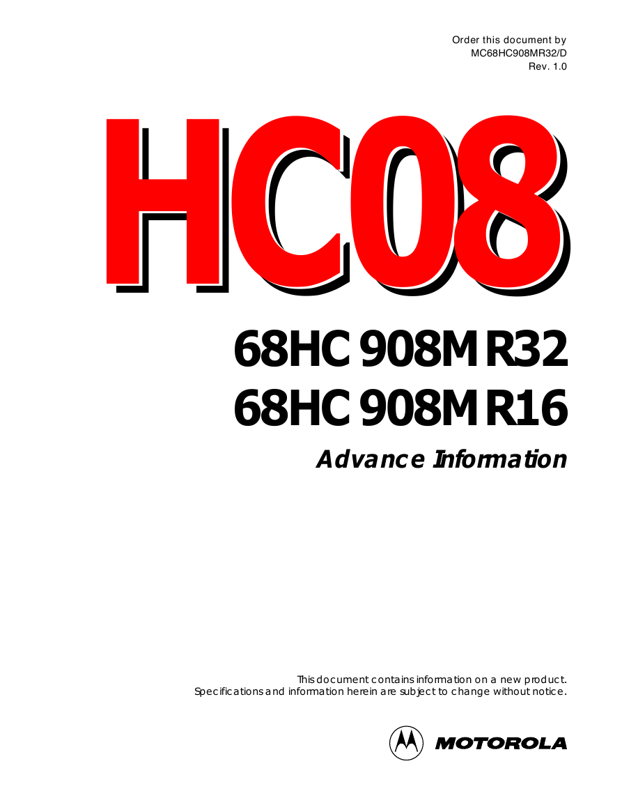
Order this document by MC68HC908MR32/D Rev. 1.0 HC08HC08HC08 68HC908MR32 68HC908MR16 Advance Information This document contains information on a new product. Specifications and information herein are subject to change without notice. D E R I U Q E R T N E M E E R G A E R U S O L C S I D - N O N
Advance Information Motorola reserves the right to make changes without further notice to any products herein to improve reliability, function or design. Motorola does not assume any liability arising out of the application or use of any product or circuit described herein; neither does it convey any license under its patent rights nor the rights of others. Motorola products are not designed, intended, or authorized for use as components in systems intended for surgical implant into the body, or other applications intended to support or sustain life, or for any other application in which the failure of the Motorola product could create a situation where personal injury or death may occur. Should Buyer purchase or use Motorola products for any such unintended or unauthorized application, Buyer shall indemnify and hold Motorola and its officers, employees, subsidiaries, affiliates, and distributors harmless against all claims, costs, damages, and expenses, and reasonable attorney fees arising out of, directly or indirectly, any claim of personal injury or death associated with such unintended or unauthorized use, even if such claim alleges that Motorola was negligent regarding the design or manufacture of the part. © Motorola, Inc., 2000 Advance Information 2 MC68HC908MR16/MC68HC908MR32 — Rev. 1.0 MOTOROLA
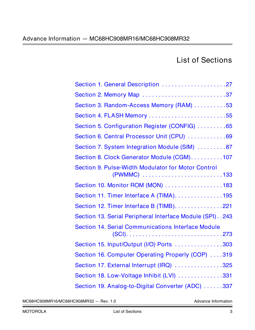
Advance Information — MC68HC908MR16/MC68HC908MR32 List of Sections Section 1. General Description . . . . . . . . . . . . . . . . . . . .27 Section 2. Memory Map . . . . . . . . . . . . . . . . . . . . . . . . . .37 Section 3. Random-Access Memory (RAM) . . . . . . . . . .53 Section 4. FLASH Memory . . . . . . . . . . . . . . . . . . . . . . . .55 Section 5. Configuration Register (CONFIG) . . . . . . . . .65 Section 6. Central Processor Unit (CPU) . . . . . . . . . . . .69 Section 7. System Integration Module (SIM) . . . . . . . . .87 Section 8. Clock Generator Module (CGM). . . . . . . . . .107 Section 9. Pulse-Width Modulator for Motor Control (PWMMC) . . . . . . . . . . . . . . . . . . . . . . . . . 133 Section 10. Monitor ROM (MON) . . . . . . . . . . . . . . . . . . 183 Section 11. Timer Interface A (TIMA). . . . . . . . . . . . . . . 195 Section 12. Timer Interface B (TIMB). . . . . . . . . . . . . . . 221 Section 13. Serial Peripheral Interface Module (SPI) . . 243 Section 14. Serial Communications Interface Module (SCI). . . . . . . . . . . . . . . . . . . . . . . . . . . . . . 273 Section 15. Input/Output (I/O) Ports . . . . . . . . . . . . . . . 303 Section 16. Computer Operating Properly (COP) . . . . 319 Section 17. External Interrupt (IRQ) . . . . . . . . . . . . . . . 325 Section 18. Low-Voltage Inhibit (LVI) . . . . . . . . . . . . . .331 Section 19. Analog-to-Digital Converter (ADC) . . . . . . 337 MC68HC908MR16/MC68HC908MR32 — Rev. 1.0 Advance Information MOTOROLA List of Sections 3
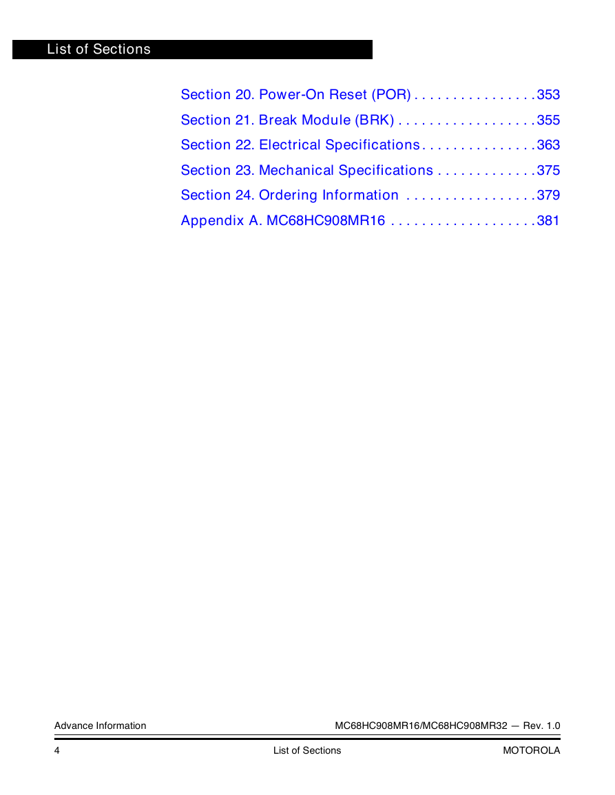
List of Sections Section 20. Power-On Reset (POR) . . . . . . . . . . . . . . . . 353 Section 21. Break Module (BRK) . . . . . . . . . . . . . . . . . . 355 Section 22. Electrical Specifications. . . . . . . . . . . . . . . 363 Section 23. Mechanical Specifications . . . . . . . . . . . . . 375 Section 24. Ordering Information . . . . . . . . . . . . . . . . . 379 Appendix A. MC68HC908MR16 . . . . . . . . . . . . . . . . . . .381 Advance Information MC68HC908MR16/MC68HC908MR32 — Rev. 1.0 4 List of Sections MOTOROLA
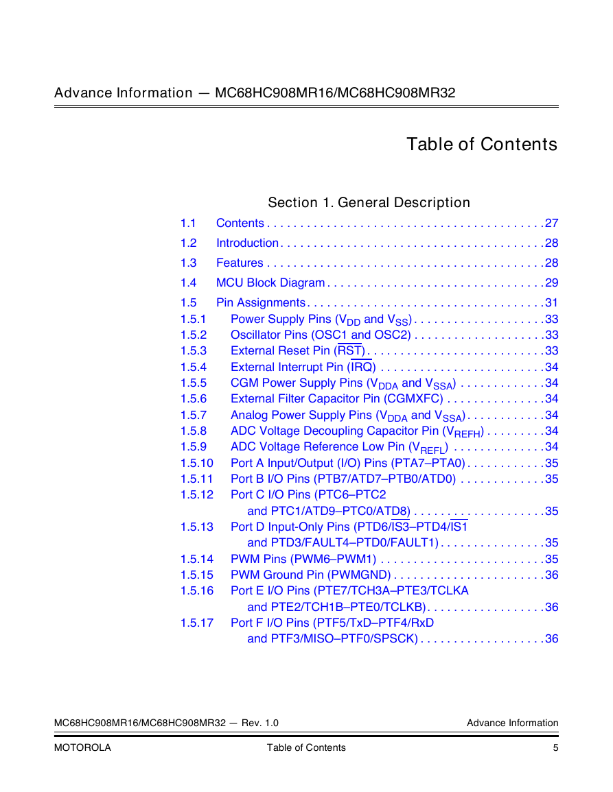
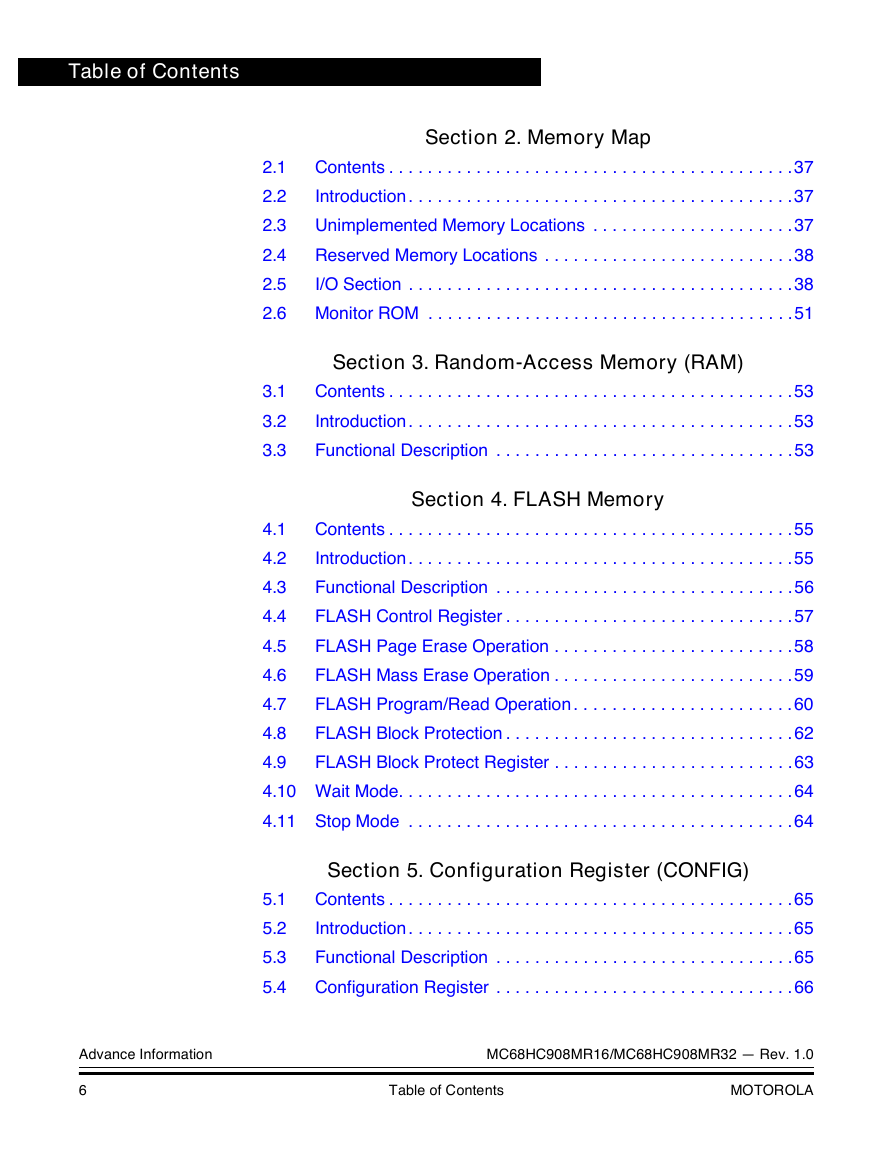
Advance Information — MC68HC908MR16/MC68HC908MR32 Table of Contents Section 1. General Description Contents . . . . . . . . . . . . . . . . . . . . . . . . . . . . . . . . . . . . . . . . . .27 1.1 Introduction . . . . . . . . . . . . . . . . . . . . . . . . . . . . . . . . . . . . . . . .28 1.2 1.3 Features . . . . . . . . . . . . . . . . . . . . . . . . . . . . . . . . . . . . . . . . . .28 1.4 MCU Block Diagram . . . . . . . . . . . . . . . . . . . . . . . . . . . . . . . . .29 Pin Assignments . . . . . . . . . . . . . . . . . . . . . . . . . . . . . . . . . . . .31 1.5 Power Supply Pins (VDD and VSS) . . . . . . . . . . . . . . . . . . . .33 1.5.1 1.5.2 Oscillator Pins (OSC1 and OSC2) . . . . . . . . . . . . . . . . . . . .33 External Reset Pin (RST) . . . . . . . . . . . . . . . . . . . . . . . . . . .33 1.5.3 1.5.4 External Interrupt Pin (IRQ) . . . . . . . . . . . . . . . . . . . . . . . . .34 CGM Power Supply Pins (VDDA and VSSA) . . . . . . . . . . . . .34 1.5.5 External Filter Capacitor Pin (CGMXFC) . . . . . . . . . . . . . . .34 1.5.6 Analog Power Supply Pins (VDDA and VSSA) . . . . . . . . . . . .34 1.5.7 1.5.8 ADC Voltage Decoupling Capacitor Pin (VREFH) . . . . . . . . .34 ADC Voltage Reference Low Pin (VREFL) . . . . . . . . . . . . . .34 1.5.9 Port A Input/Output (I/O) Pins (PTA7–PTA0) . . . . . . . . . . . .35 1.5.10 1.5.11 Port B I/O Pins (PTB7/ATD7–PTB0/ATD0) . . . . . . . . . . . . .35 Port C I/O Pins (PTC6–PTC2 1.5.12 and PTC1/ATD9–PTC0/ATD8) . . . . . . . . . . . . . . . . . . . .35 1.5.13 Port D Input-Only Pins (PTD6/IS3–PTD4/IS1 1.5.14 1.5.15 1.5.16 and PTD3/FAULT4–PTD0/FAULT1) . . . . . . . . . . . . . . . .35 PWM Pins (PWM6–PWM1) . . . . . . . . . . . . . . . . . . . . . . . . .35 PWM Ground Pin (PWMGND) . . . . . . . . . . . . . . . . . . . . . . .36 Port E I/O Pins (PTE7/TCH3A–PTE3/TCLKA and PTE2/TCH1B–PTE0/TCLKB). . . . . . . . . . . . . . . . . .36 1.5.17 Port F I/O Pins (PTF5/TxD–PTF4/RxD and PTF3/MISO–PTF0/SPSCK) . . . . . . . . . . . . . . . . . . .36 MC68HC908MR16/MC68HC908MR32 — Rev. 1.0 Advance Information MOTOROLA Table of Contents 5
Table of Contents Section 2. Memory Map Contents . . . . . . . . . . . . . . . . . . . . . . . . . . . . . . . . . . . . . . . . . .37 2.1 Introduction . . . . . . . . . . . . . . . . . . . . . . . . . . . . . . . . . . . . . . . .37 2.2 Unimplemented Memory Locations . . . . . . . . . . . . . . . . . . . . .37 2.3 Reserved Memory Locations . . . . . . . . . . . . . . . . . . . . . . . . . .38 2.4 2.5 I/O Section . . . . . . . . . . . . . . . . . . . . . . . . . . . . . . . . . . . . . . . .38 2.6 Monitor ROM . . . . . . . . . . . . . . . . . . . . . . . . . . . . . . . . . . . . . .51 Section 3. Random-Access Memory (RAM) 3.1 3.2 3.3 Contents . . . . . . . . . . . . . . . . . . . . . . . . . . . . . . . . . . . . . . . . . .53 Introduction . . . . . . . . . . . . . . . . . . . . . . . . . . . . . . . . . . . . . . . .53 Functional Description . . . . . . . . . . . . . . . . . . . . . . . . . . . . . . .53 Section 4. FLASH Memory Contents . . . . . . . . . . . . . . . . . . . . . . . . . . . . . . . . . . . . . . . . . .55 4.1 Introduction . . . . . . . . . . . . . . . . . . . . . . . . . . . . . . . . . . . . . . . .55 4.2 Functional Description . . . . . . . . . . . . . . . . . . . . . . . . . . . . . . .56 4.3 FLASH Control Register . . . . . . . . . . . . . . . . . . . . . . . . . . . . . .57 4.4 FLASH Page Erase Operation . . . . . . . . . . . . . . . . . . . . . . . . .58 4.5 FLASH Mass Erase Operation . . . . . . . . . . . . . . . . . . . . . . . . .59 4.6 FLASH Program/Read Operation . . . . . . . . . . . . . . . . . . . . . . .60 4.7 FLASH Block Protection . . . . . . . . . . . . . . . . . . . . . . . . . . . . . .62 4.8 FLASH Block Protect Register . . . . . . . . . . . . . . . . . . . . . . . . .63 4.9 4.10 Wait Mode. . . . . . . . . . . . . . . . . . . . . . . . . . . . . . . . . . . . . . . . .64 4.11 Stop Mode . . . . . . . . . . . . . . . . . . . . . . . . . . . . . . . . . . . . . . . .64 Section 5. Configuration Register (CONFIG) 5.1 5.2 5.3 5.4 Contents . . . . . . . . . . . . . . . . . . . . . . . . . . . . . . . . . . . . . . . . . .65 Introduction . . . . . . . . . . . . . . . . . . . . . . . . . . . . . . . . . . . . . . . .65 Functional Description . . . . . . . . . . . . . . . . . . . . . . . . . . . . . . .65 Configuration Register . . . . . . . . . . . . . . . . . . . . . . . . . . . . . . .66 Advance Information MC68HC908MR16/MC68HC908MR32 — Rev. 1.0 6 Table of Contents MOTOROLA
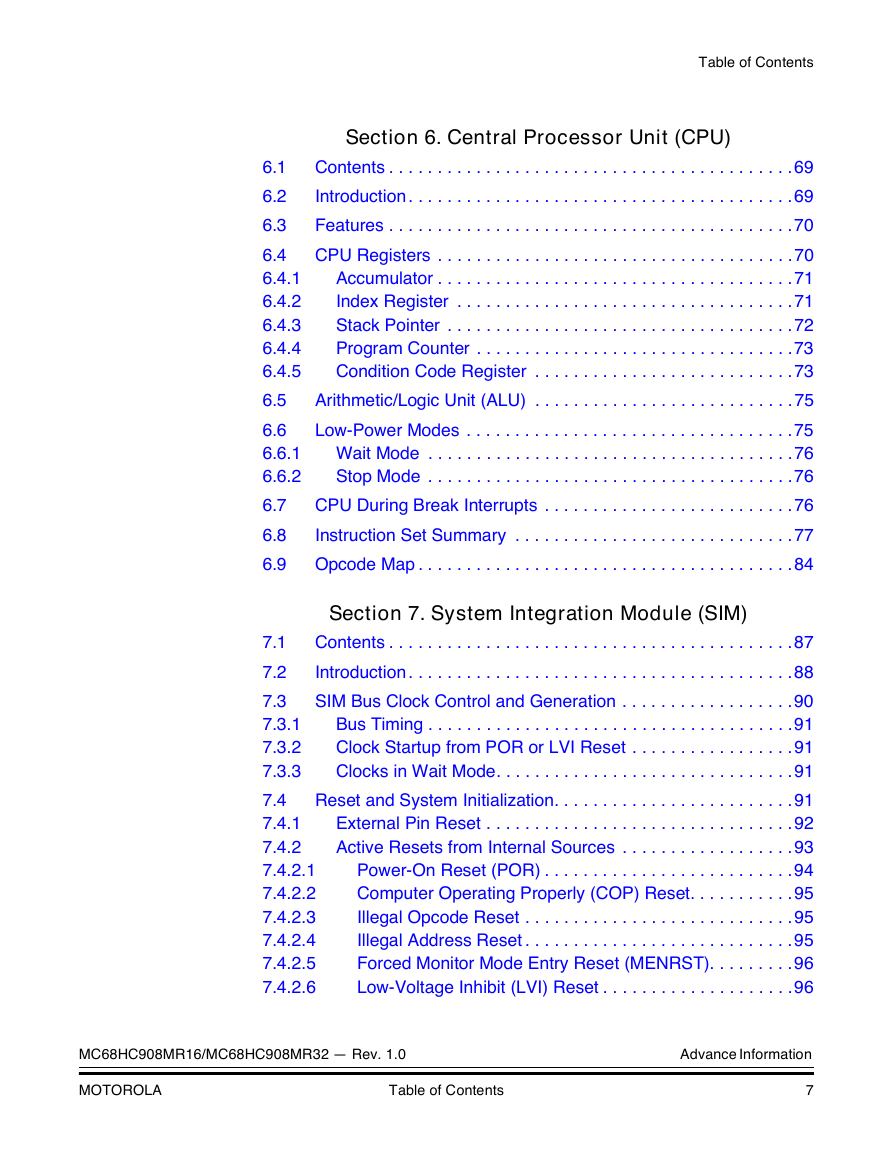
Table of Contents Section 6. Central Processor Unit (CPU) 6.1 6.2 6.3 6.4 6.4.1 6.4.2 6.4.3 6.4.4 6.4.5 6.5 6.6 6.6.1 6.6.2 6.7 6.8 6.9 Contents . . . . . . . . . . . . . . . . . . . . . . . . . . . . . . . . . . . . . . . . . .69 Introduction . . . . . . . . . . . . . . . . . . . . . . . . . . . . . . . . . . . . . . . .69 Features . . . . . . . . . . . . . . . . . . . . . . . . . . . . . . . . . . . . . . . . . .70 CPU Registers . . . . . . . . . . . . . . . . . . . . . . . . . . . . . . . . . . . . .70 Accumulator . . . . . . . . . . . . . . . . . . . . . . . . . . . . . . . . . . . . .71 Index Register . . . . . . . . . . . . . . . . . . . . . . . . . . . . . . . . . . .71 Stack Pointer . . . . . . . . . . . . . . . . . . . . . . . . . . . . . . . . . . . .72 Program Counter . . . . . . . . . . . . . . . . . . . . . . . . . . . . . . . . .73 Condition Code Register . . . . . . . . . . . . . . . . . . . . . . . . . . .73 Arithmetic/Logic Unit (ALU) . . . . . . . . . . . . . . . . . . . . . . . . . . .75 Low-Power Modes . . . . . . . . . . . . . . . . . . . . . . . . . . . . . . . . . .75 Wait Mode . . . . . . . . . . . . . . . . . . . . . . . . . . . . . . . . . . . . . .76 Stop Mode . . . . . . . . . . . . . . . . . . . . . . . . . . . . . . . . . . . . . .76 CPU During Break Interrupts . . . . . . . . . . . . . . . . . . . . . . . . . .76 Instruction Set Summary . . . . . . . . . . . . . . . . . . . . . . . . . . . . .77 Opcode Map . . . . . . . . . . . . . . . . . . . . . . . . . . . . . . . . . . . . . . .84 Section 7. System Integration Module (SIM) 7.1 7.2 7.3 7.3.1 7.3.2 7.3.3 7.4 7.4.1 7.4.2 7.4.2.1 7.4.2.2 7.4.2.3 7.4.2.4 7.4.2.5 7.4.2.6 Contents . . . . . . . . . . . . . . . . . . . . . . . . . . . . . . . . . . . . . . . . . .87 Introduction . . . . . . . . . . . . . . . . . . . . . . . . . . . . . . . . . . . . . . . .88 SIM Bus Clock Control and Generation . . . . . . . . . . . . . . . . . .90 Bus Timing . . . . . . . . . . . . . . . . . . . . . . . . . . . . . . . . . . . . . .91 Clock Startup from POR or LVI Reset . . . . . . . . . . . . . . . . .91 Clocks in Wait Mode. . . . . . . . . . . . . . . . . . . . . . . . . . . . . . .91 Reset and System Initialization. . . . . . . . . . . . . . . . . . . . . . . . .91 External Pin Reset . . . . . . . . . . . . . . . . . . . . . . . . . . . . . . . .92 Active Resets from Internal Sources . . . . . . . . . . . . . . . . . .93 Power-On Reset (POR) . . . . . . . . . . . . . . . . . . . . . . . . . .94 Computer Operating Properly (COP) Reset. . . . . . . . . . .95 Illegal Opcode Reset . . . . . . . . . . . . . . . . . . . . . . . . . . . .95 Illegal Address Reset . . . . . . . . . . . . . . . . . . . . . . . . . . . .95 Forced Monitor Mode Entry Reset (MENRST). . . . . . . . .96 Low-Voltage Inhibit (LVI) Reset . . . . . . . . . . . . . . . . . . . .96 MC68HC908MR16/MC68HC908MR32 — Rev. 1.0 Advance Information MOTOROLA Table of Contents 7
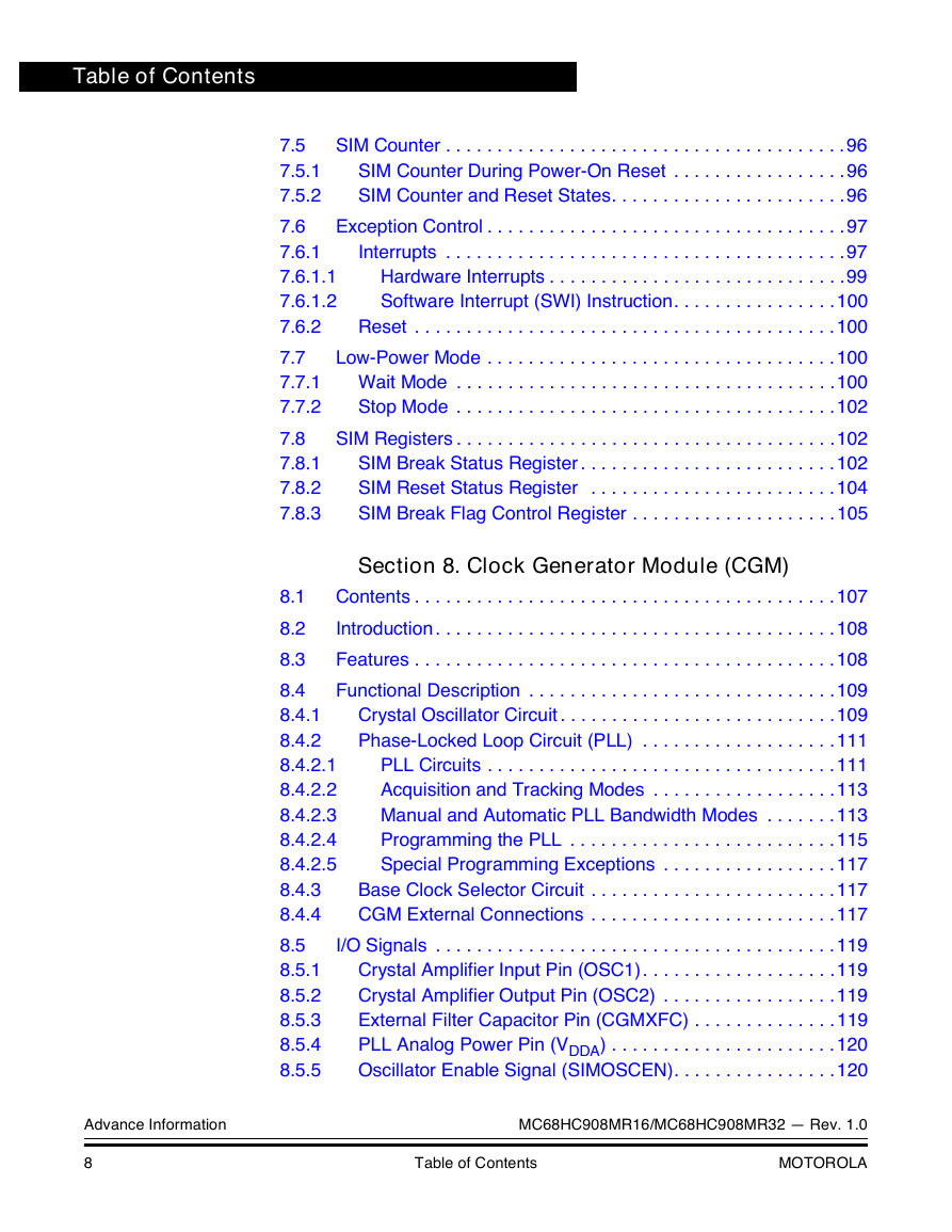
Table of Contents 7.5 7.5.1 7.5.2 7.6 7.6.1 7.6.1.1 7.6.1.2 7.6.2 7.7 7.7.1 7.7.2 7.8 7.8.1 7.8.2 7.8.3 SIM Counter . . . . . . . . . . . . . . . . . . . . . . . . . . . . . . . . . . . . . . .96 SIM Counter During Power-On Reset . . . . . . . . . . . . . . . . .96 SIM Counter and Reset States. . . . . . . . . . . . . . . . . . . . . . .96 Exception Control . . . . . . . . . . . . . . . . . . . . . . . . . . . . . . . . . . .97 Interrupts . . . . . . . . . . . . . . . . . . . . . . . . . . . . . . . . . . . . . . .97 Hardware Interrupts . . . . . . . . . . . . . . . . . . . . . . . . . . . . .99 Software Interrupt (SWI) Instruction. . . . . . . . . . . . . . . .100 Reset . . . . . . . . . . . . . . . . . . . . . . . . . . . . . . . . . . . . . . . . .100 Low-Power Mode . . . . . . . . . . . . . . . . . . . . . . . . . . . . . . . . . .100 Wait Mode . . . . . . . . . . . . . . . . . . . . . . . . . . . . . . . . . . . . .100 Stop Mode . . . . . . . . . . . . . . . . . . . . . . . . . . . . . . . . . . . . .102 SIM Registers . . . . . . . . . . . . . . . . . . . . . . . . . . . . . . . . . . . . .102 SIM Break Status Register . . . . . . . . . . . . . . . . . . . . . . . . .102 SIM Reset Status Register . . . . . . . . . . . . . . . . . . . . . . . .104 SIM Break Flag Control Register . . . . . . . . . . . . . . . . . . . .105 Section 8. Clock Generator Module (CGM) 8.1 8.2 8.3 8.4 8.4.1 8.4.2 8.4.2.1 8.4.2.2 8.4.2.3 8.4.2.4 8.4.2.5 8.4.3 8.4.4 8.5 8.5.1 8.5.2 8.5.3 8.5.4 8.5.5 Contents . . . . . . . . . . . . . . . . . . . . . . . . . . . . . . . . . . . . . . . . .107 Introduction . . . . . . . . . . . . . . . . . . . . . . . . . . . . . . . . . . . . . . .108 Features . . . . . . . . . . . . . . . . . . . . . . . . . . . . . . . . . . . . . . . . .108 Functional Description . . . . . . . . . . . . . . . . . . . . . . . . . . . . . .109 Crystal Oscillator Circuit . . . . . . . . . . . . . . . . . . . . . . . . . . .109 Phase-Locked Loop Circuit (PLL) . . . . . . . . . . . . . . . . . . .111 PLL Circuits . . . . . . . . . . . . . . . . . . . . . . . . . . . . . . . . . .111 Acquisition and Tracking Modes . . . . . . . . . . . . . . . . . .113 Manual and Automatic PLL Bandwidth Modes . . . . . . .113 Programming the PLL . . . . . . . . . . . . . . . . . . . . . . . . . .115 Special Programming Exceptions . . . . . . . . . . . . . . . . .117 Base Clock Selector Circuit . . . . . . . . . . . . . . . . . . . . . . . .117 CGM External Connections . . . . . . . . . . . . . . . . . . . . . . . .117 I/O Signals . . . . . . . . . . . . . . . . . . . . . . . . . . . . . . . . . . . . . . .119 Crystal Amplifier Input Pin (OSC1). . . . . . . . . . . . . . . . . . .119 Crystal Amplifier Output Pin (OSC2) . . . . . . . . . . . . . . . . .119 External Filter Capacitor Pin (CGMXFC) . . . . . . . . . . . . . .119 PLL Analog Power Pin (VDDA) . . . . . . . . . . . . . . . . . . . . . .120 Oscillator Enable Signal (SIMOSCEN). . . . . . . . . . . . . . . .120 Advance Information MC68HC908MR16/MC68HC908MR32 — Rev. 1.0 8 Table of Contents MOTOROLA
分享到:
收藏