undefined
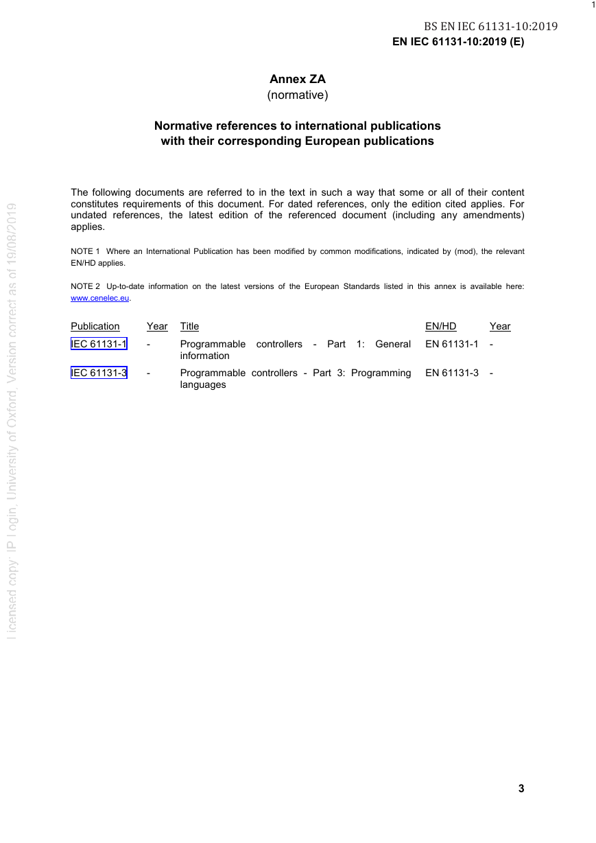
Annex ZA(normative)Normative references to international publicationswith their corresponding European publications
English
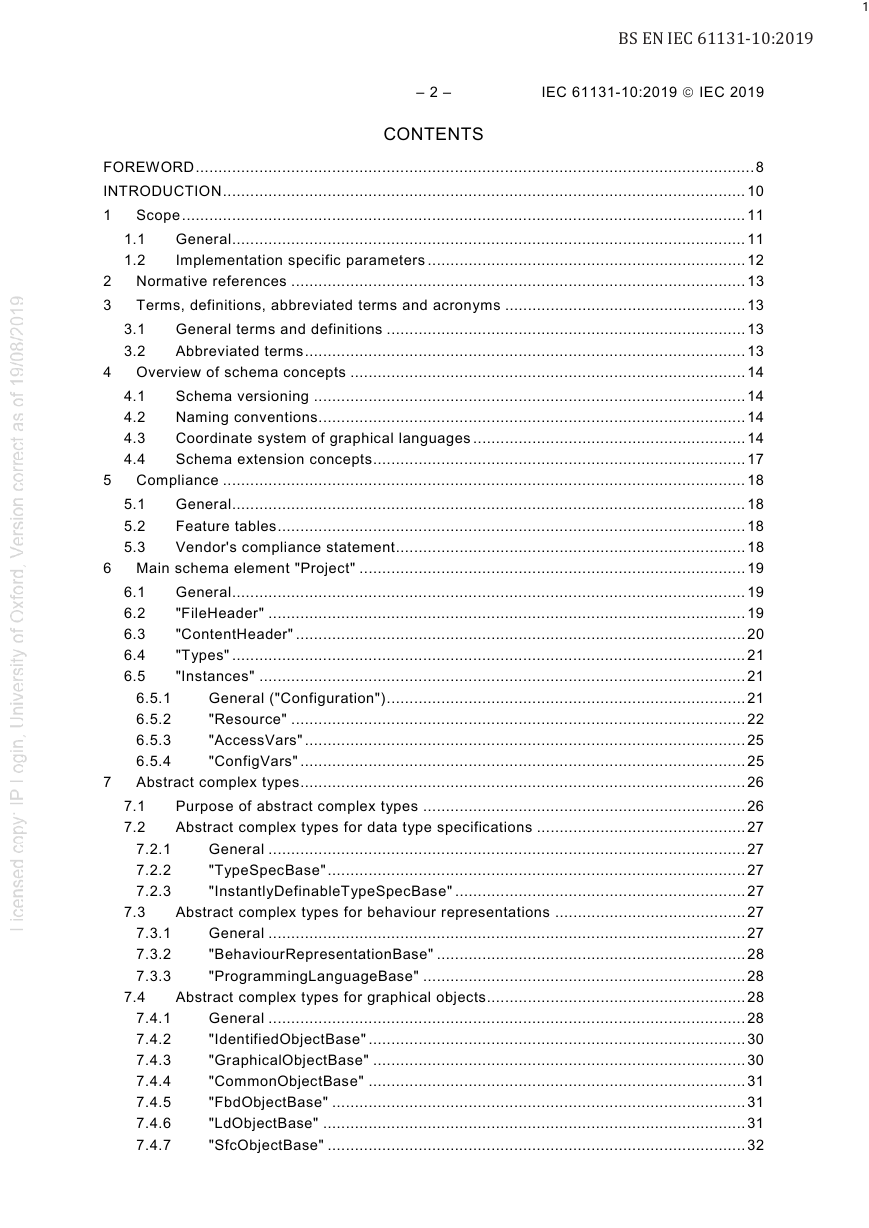
CONTENTS
FOREWORD
INTRODUCTION
1 Scope
1.1 General
Figures
Figure 1 – Main overview of XML exchange format usage (example)
1.2 Implementation specific parameters
2 Normative references
3 Terms, definitions, abbreviated terms and acronyms
3.1 General terms and definitions
3.2 Abbreviated terms
4 Overview of schema concepts
4.1 Schema versioning
4.2 Naming conventions
4.3 Coordinate system of graphical languages
Figure 2 – Mapping coordinate information to the coordinate system
Figure 3 – Transforming position using the scaling information
4.4 Schema extension concepts
Figure 4 – Objects anchor points and object rectangles examples
5 Compliance
5.1 General
5.2 Feature tables
5.3 Vendor's compliance statement
6 Main schema element "Project"
6.1 General
6.2 "FileHeader"
Figure 5 – Main schema element "Project"
6.3 "ContentHeader"
Figure 6 – Element "FileHeader"
Figure 7 – Element "ContentHeader"
6.4 "Types"
6.5 "Instances"
6.5.1 General ("Configuration")
Figure 8 – Element "Types"
6.5.2 "Resource"
Figure 9 – Element "Instances"
Figure 10 – Element "Resource"
Figure 11 – Element "ProgramInstance"
6.5.3 "AccessVars"
6.5.4 "ConfigVars"
Figure 12 – Element "AccessVars"
7 Abstract complex types
7.1 Purpose of abstract complex types
Figure 13 – Element "ConfigVars"
7.2 Abstract complex types for data type specifications
7.2.1 General
7.2.2 "TypeSpecBase"
7.2.3 "InstantlyDefinableTypeSpecBase"
7.3 Abstract complex types for behaviour representations
7.3.1 General
Figure 14 – Extension relationship among complex types for data type specifications
7.3.2 "BehaviourRepresentationBase"
7.3.3 "ProgrammingLanguageBase"
7.4 Abstract complex types for graphical objects
7.4.1 General
Figure 15 – Extension relationship among complex types for behaviour representations
Figure 16 – Extension relationship among complex types for graphical objects
7.4.2 "IdentifiedObjectBase"
7.4.3 "GraphicalObjectBase"
Figure 17 – Complex type "IdentifiedObjectBase"
Figure 18 – Complex type "GraphicalObjectBase"
7.4.4 "CommonObjectBase"
7.4.5 "FbdObjectBase"
7.4.6 "LdObjectBase"
Figure 19 – Complex type "CommonObjectBase"
Figure 20 – Complex type "FbdObjectBase"
7.4.7 "SfcObjectBase"
7.4.8 "NetworkBase"
Figure 21 – Complex type "LdObjectBase"
Figure 22 – Complex type "SfcObjectBase"
7.5 Abstract complex types for textual constructs
7.5.1 General
Figure 23 – Complex type "NetworkBase"
7.5.2 "TextualObjectBase"
Figure 24 – Extension relationship among complex types for textual objects
7.5.3 "NamespaceContentBase"
Figure 25 – Complex type "TextualObjectBase"
Figure 26 – Complex type "NamespaceContentBase"
7.5.4 "TaskBase"
8 Namespace declaration
Figure 27 – Complex type "TaskBase"
Figure 28 – Complex type "NamespaceDecl"
9 User-defined data type declaration
9.1 "UserDefinedTypeDecl"
9.2 "ArrayTypeSpec"
Figure 29 – Complex type "UserDefinedTypeDecl"
9.3 "DirectlyDerivedTypeSpec"
9.4 "EnumTypeSpec"
Figure 30 – Complex type "ArrayTypeSpec"
Figure 31 – Complex type "DirectlyDerivedTypeSpec"
9.5 "EnumTypeWithNamedValueSpec"
9.6 "StructTypeSpec"
Figure 32 – Complex type "EnumTypeSpec"
Figure 33 – Complex type "EnumTypeWithNamedValueSpec"
9.7 "SubrangeTypeSpec"
9.8 "ReferenceTypeSpec"
Figure 34 – Complex type "StructTypeSpec"
Figure 35 – Complex type "SubrangeTypeSpec"
Figure 36 – Complex type "ReferenceTypeSpec"
9.9 "ElementaryType"
10 POU declaration
10.1 "PouDecl"
10.2 "Program"
Figure 37 – Complex type "PouDecl"
Figure 38 – Complex type "Program"
10.3 "FunctionBlock"
Figure 39 – Complex type "FunctionBlock"
10.4 "Class"
Figure 40 – Complex type "Class"
10.5 "Function"
Figure 41 – Complex type "Function"
10.6 "Interface"
10.7 "Action"
Figure 42 – Complex type "Interface"
Figure 43 – Complex type "Action"
10.8 "NamedTransition"
10.9 "MethodPrototype"
Figure 44 – Complex type "NamedTransition"
10.10 "Method"
Figure 45 – Complex type "MethodPrototype"
Figure 46 – Complex type "Method"
10.11 "ParameterSet"
Figure 47 – Complex type "ParameterSet"
10.12 "VarListWithAccessSpec"
10.13 "AccessSpecifiers"
10.14 "Body"
Figure 48 – Complex type "VarListWithAccessSpec"
10.15 "BodyWithoutSFC"
10.16 "Predicate"
Figure 49 – Complex type "Body"
Figure 50 – Complex type "BodyWithoutSFC"
11 Variable declaration
11.1 "VarList"
Figure 51 – Complex type "Predicate"
Figure 52 – Complex type "VarList"
11.2 "ExternalVarList"
11.3 "VariableDecl"
Figure 53 – Complex type "ExternalVarList"
Figure 54 – Complex type "VariableDecl"
11.4 "VariableDeclPlain"
11.5 "TypeRef"
11.6 "Value"
Figure 55 – Complex type "VariableDeclPlain"
Figure 56 – Complex type "TypeRef"
11.7 "AddressExpression"
Figure 57 – Complex type "Value"
Figure 58 – Complex type "AddressExpression"
11.8 "FixedAddressExpression"
12 Behaviour representation
12.1 "IL"
12.2 "ST"
Figure 59 – Complex type "FixedAddressExpression"
Figure 60 – Complex type "IL"
Figure 61 – Complex type "ST"
12.3 "FBD"
12.4 "FbdNetwork"
12.5 "LD"
Figure 62 – Complex type "FBD"
Figure 63 – Complex type "FbdNetwork"
Figure 64 – Complex type "LD"
12.6 "LadderRung"
12.7 "SFC"
13 Graphical behaviour representation
13.1 General
Figure 65 – Complex type "LadderRung"
Figure 66 – Complex type "SFC"
13.2 Common elements
13.2.1 "Comment"
13.2.2 "Connector"
Figure 67 – Complex type "Comment"
Figure 68 – Complex type "Connector"
13.2.3 "Continuation"
13.2.4 "ActionBlocks"
Figure 69 – Complex type "Continuation"
Figure 70 – Complex type "ActionBlocks"
13.3 FBD elements
13.3.1 "Block"
Figure 71 – Complex type "Block"
13.3.2 "graphicalFormalParameterCommon"
13.3.3 "DataSource"
Figure 72 – Complex type "DataSource"
13.3.4 "DataSink"
13.3.5 "Unconnected"
Figure 73 – Complex type "DataSink"
13.3.6 "Jump"
Figure 74 – Complex type "Unconnected"
Figure 75 – Complex type "Jump"
13.3.7 "Return"
13.4 LD elements
13.4.1 "LeftPowerRail"
Figure 76 – Complex type "Return"
Figure 77 – Complex type "LeftPowerRail"
13.4.2 "RightPowerRail"
13.4.3 "Coil"
Figure 78 – Complex type "RightPowerRail"
13.4.4 "Contact"
Figure 79 – Complex type "Coil"
13.4.5 "CompareContact"
Figure 80 – Complex type "Contact"
13.5 SFC elements
13.5.1 "Step"
Figure 81 – Complex type "CompareContact"
13.5.2 "Transition"
Figure 82 – Complex type "Step"
13.5.3 "SelectionDivergence"
Figure 83 – Complex type "Transition"
13.5.4 "SelectionConvergence"
Figure 84 – Complex type "SelectionDivergence"
13.5.5 "SimultaneousDivergence"
13.5.6 "SimultaneousConvergence"
Figure 85 – Complex type "SelectionConvergence"
Figure 86 – Complex type "SimultaneousDivergence"
13.6 Connections
13.6.1 General
13.6.2 "ConnectionPointIn"
Figure 87 – Complex type "SimultaneousConvergence"
13.6.3 "Connection"
Figure 88 – Complex type "ConnectionPointIn"
Figure 89 – Complex type "Connection"
13.6.4 "FeedbackConnection"
13.6.5 "ConnectionPointOut"
Figure 90 – Complex type "FeedbackConnection"
Figure 91 – Complex type "ConnectionPointOut"
14 Resource declaration
14.1 "StandardTask"
14.2 "ParameterAssignment"
15 Miscellaneous
15.1 "XyDecimalValue"
Figure 92 – Complex type "StandardTask"
Figure 93 – Complex type "ParameterAssignment"
15.2 "AddData"
15.3 "TextBase"
15.4 "SimpleText"
Figure 94 – Complex type "XyDecimalValue"
Figure 95 – Complex type "AddData"
Figure 96 – Complex type "TextBase"
15.5 "EdgeModifierType"
Figure 97 – Complex type "SimpleText"
Annex A (normative)Formal XML exchange format schema definition
Annex B (informative)Recommended schemata
B.1 General
Figure B.1 – Only IEC 61131-3 features
Figure B.2 – Vendor specific extensions "AddData"
Figure B.3 – Vendor specific extensions (abstract complex type)
B.2 Recommended schemata to be used by "AddData"
B.3 Recommended schemata to be used by abstract complex type
Annex C (informative)Example XML document
Bibliography



 2023年江西萍乡中考道德与法治真题及答案.doc
 2012年重庆南川中考生物真题及答案.doc
 2013年江西师范大学地理学综合及文艺理论基础考研真题.doc
 2020年四川甘孜小升初语文真题及答案I卷.doc
 2020年注册岩土工程师专业基础考试真题及答案.doc
 2023-2024学年福建省厦门市九年级上学期数学月考试题及答案.doc
 2021-2022学年辽宁省沈阳市大东区九年级上学期语文期末试题及答案.doc
 2022-2023学年北京东城区初三第一学期物理期末试卷及答案.doc
 2018上半年江西教师资格初中地理学科知识与教学能力真题及答案.doc
 2012年河北国家公务员申论考试真题及答案-省级.doc
 2020-2021学年江苏省扬州市江都区邵樊片九年级上学期数学第一次质量检测试题及答案.doc
 2022下半年黑龙江教师资格证中学综合素质真题及答案.doc