logo资料库

ICC Student Guide.pdf

第1页 / 共504页
第2页 / 共504页
第3页 / 共504页
第4页 / 共504页
第5页 / 共504页
第6页 / 共504页
第7页 / 共504页
第8页 / 共504页
资料共504页,剩余部分请下载后查看
Contents
Unit i: Introduction&Overview
Unit 1: Data Setup&Basic Flow
Unit 2: Design Planning
Unit 3: Placement
Unit 4: Clock Tree Synthesis
Unit 5: Multi Scenario Optimization
Unit 6: Routing and Crosstalk
Unit 7: Chip Finishing and DFM
Unit CS: Customer Support
Unit i: Introduction&Overview
Facilities
Workshop Goal
Target Audience
Workshop Prerequisites
Introductions
Curriculum Flow
Agenda
High-Level IC Compiler Flow
Lab 0: IC Compiler GUI-MainWindow
Lab 0: IC Compiler GUI-LayoutWindow
Lab 0A: IC Compiler GUI
Unit 1: Date Setup&Basic Flow
Unit Objectives
A Word of Caution About Scripts and Flows
General IC Compiler Flow
Data Setup
Logical Libraries
Physical Reference Libraries
Milkyway Structure of Physical Libraries
1.Specify the Logical Libraries
2.Define 'logic0' and 'logic1'
IC Compiler Initialization Files
3.Create a "Container": The Design Library
Initial Structure of a Milkyway Design Library
The Technology File(.tf file)
Example of a Technology File
The check_library Command
4.Specify TLU+ Parasitic RC Model Files
Timing is Based on Cell and Net Delays
TLU+ Models
Mapping file
5a.Read the Netlist and Create a Design CEL
Must Uniquify Multiply Instantiated Designs
Linking: Resolving References
Milkyway Design Library with Design Cell
5b.Shortcut:Import the Netlist
6.Verify Logical Libraries Are Loaded
7.Define Logical Power/Ground Connections
8.Apply and Check Timing Constraints
Timing Constraints
9.Ensure Proper Modeling of Clock Tree
Test for Understanding
10.Apply Timing and Optimization Controls
Available Timing and Optimization Controls
Timing and Optimization Setup Example
Enable Multiple Clocks per Register
Enable Constant Propagation
Enable Multiple Port Net Buffering
Enable Constant Net Buffering, if Needed
Apply Timing Derating for On-Chip Variation
Define "Don‘t Use" or "Preferred" Cells
Keep Spare or Unloaded Cells
Apply Area Constraint for Area Recovery
Apply a Power and Area Critical Range
IC Compiler Organizes Paths into Groups
General Problem:Sub-Critical Paths Ingored
Serious Problem:Reg-to-Reg Paths Ignored
Solution:User-Defined Path Groups
Define Path Groups for I/O Paths,if needed
Prevent Buffering of Clock-as-Data Networks
Modify Optimization Priority if Needed
Enable Recovery and Removal Timing Arcs
11.Perform a 'Timing Sanity Check'
12.Remove Unwanted "Ideal Net/Networks"
13.Save the Design
Design Library with New Design Cell
UNIX Manipulation of a Milkyway Database
Restoring Variables
Restoring Logical Library and TLU+ Settings
Loading an Existing Cell After Exiting ICC
Data Setup Summary
Data Setup Example(1 of 3)
Data Setup Example(2 of 3)
Data Setup Example(3 of 3)
Test for Understanding(1 of 2)
Test for Understanding(2 of 2
General IC Compiler Flow
Design Planning
Load an Existing Floorplan
Placement and Related Optimizations
Clock Tree Synthesis
Routing
Chip Finishing
Analyzing the Results(1/2)
Analyzing the Results(2/2)
Example “run” Script
Basic Flow Summary
Lab 1: Design Setup and Basic Flow
Unit 2: Design Planning
Unit Objectives
General IC Compiler Flow
Terminology
ICC Design Planning and Re-Synthesis Flow
Select the Design Planning Task GUI
Create the Starting Floorplan
Create Physical-only Pad Cells
Specify Pad Cell Locations
Initialize the Floorplan
Core Area Parameters
Floorplan After Initialization
Insert Pad Filler Cells
Create P/G Pad Rings
Prior to Virtual Flat Placement
Ignore Extra Routing Layers
Constraining Macros
Manual Macro Placement
Macro Constraints: Arrays
Macro Constraints: Legal Orientation Option
Macro Constraints: Anchor Bound Option
Macro Constraints: Side Channel Option
Macro Constraints: Relative Location
Congestion Potential Around Macro Cells
Apply Global Placement Blockages
Apply Specific Placement Blockages
Summary: Create the Starting Floorplan
Test For Understanding
Perform Virtual Flat Placement
Set Placement Strategy Parameters
VF Placement with Virtual IPO(VIPO)
Perform Virtual Flat Placement
Hierarchy Aware Placement or Gravity
Summary: Virtual Flat Placement
Reduce Congestion
Is the Design Congested?
Understanding the Congestion Calculation
Congestion Guidelines
Modify Macro Placement Constraints
Apply Standard Cell Placement Constraints
Is High Cell Density Causing Congestion?
Reducing Cell Density Hotspots
Coordinate-based Placement Blockages
Modify "FP Placement Strategy" Options
Placement Strategy Options and Defaults
Macro Placement Strategy Examples
Perform Congestion-driven Placement
Invoke the High Effort Congestion Strategy
Modify the Floorplan
"Fix" All Macro Cell Placement
Summary; Reduce Congestion
Test For Understanding(1 of 2)
Test For Understanding(2 of 2)
Synthesize the Power Network(PNS)
Power Network Synthesis(PNS)
Define Logical Power/Ground Connections
Apply Power Network Constraints
Synthesize and Analyze the Power Network
Modify Constraints and Re-synthesize
Create Virtual Power/Ground Pads if Needed
Add Additional P/G Pads to TDF and Re-load
Commit the Power Network
Connect P/G Pins and Create Power Rails
Analyze the Power Network
Apply Power Net Placement Blockages
Perform Incremental Virtual Flat Placement
Summary: Synthesize the Power Network
Reduce Delay
Global Route and Analyze Congestion
Modify Power Net Placement Blockages
Return to "Reduce Congestion", if Needed
Extract Net Parasitics and Analyze Timing
Perform In-Place Optimization
Modify Floorplan or Re-Synthesize, if Needed
Summary: Reduce Delay
Write Out the Floorplan and DEF Files
Write Out Floorplan and DEF Files
Re-Synthesize Before Placement
Test For Understanding(1 of 2)
Test For Understanding(2 of 2)
Summary
Lab2: Design Planning
Appendix A
Floorplan Exploration and Re-Synthesis Flow
Floorplan Exploration Objectives
Overview: Floorplan Exploration
Load the Floorplan Definition (DEF) Files
Pre-exploration Settings and Checks
Check Placement Readiness
Perform Low-effort Placement Optimization
Check and Fix Congestion
Modify the Floorplan
Analyze and Fix Timing
Write Out the Floorplan Files
Summary: Floorplan Exploration
Summary: 3rd Party Design Planning Flow
Unit 3: Placement
Unit Objectives
General IC Compiler Flow
Design Status Prior to Placement
IC Compiler Placement Flow
Placement Setup and Checks
"Fix" all Macro Cell Placements
Verify pnet Options and Ignored Layers
Verify Keepout Variable Settings (if used)
Non-Default Clock Routing
Specify Non-Default Routing Rules
Check Placement Readiness
Summary: Placement Setup and Checks
Design-for-Test(DFT) Setup
Pre-Existing Scan Chains
The Issue with Existing Scan Chains
SCANDEF-Based Chain Reordering
Re-ordering Chains within Same "Partition"
Example SCANDEF from Synthesis with DFT
Example: Placement with Existing Ordering
Example: Reordering Within Scan-Chains
Example: Reordering Within Partitions
Placement-Based Scan Chain Re-Ordering
Consider Extreme Block Aspect Ratios
Summary: DFT Setup
Power Setup
Where Does Power Dissipation Occur?
Leakage Power Optimization
Report Multi-Vth Cells
Reducing Dynamic Power Dissipation
Switching Activity Terminology
SAIF File Provides Switching Activity
What if SAIF is Not Available?
Dynamic Power Optimization: LPP
Dynamic Power Optimization: GLPO
Summary: Power Optimization Flow
Test For Understanding
Placement and Optimization
Overview: Placement and Optimization
The Initial Placement and Optimization
Placement and Logic Optimization
Considerations for Using -congestion
No Hold Time Fixing
Post-Placement Analysis
Incremental Optimization
Apply Placement Constraints As Needed
Recall Problem: Sub-Critical Paths Ignored
Solution #1: User-defined Path Groups
Solution #2: Apply a Critical Range
Solution #3: Prioritizing Path Groups
Example: -weight
Complete Example
Incremental Logic Optimization: psynopt
Summary: Incremental Optimization
If the Design is Still Seriously Congested ...
Enable Global Router During Optimization
Summary:Placement and Optimization
Improving Congestion and Setup Timing
Overview: Improve Congestion/Timing
refine_placement
psynopt
Summary: Improve Congestion/Setup Timing
Test For Understanding(1 of 2)
Test For Understanding(2 of 2)
Techniques with More User Control
Build User-Controlled Balanced Buffer Trees
Build Skew-Optimized Buffer Trees
Relative Placement
What's Special about Data Path Logic?
The Ideal Layout for Data Path
Data Path Layout using Traditional P&R Tool
Traditional Solution: Custom/Manual Layout
IC Compiler's Solution: Relative Placement
Fetures and Benefits of Relative Placement
Candidates for Relative Placement
More Information on Relative Placement
Summary
Lab 3: Placement
Unit 4: Clock Tree Synthesis
Unit Objectives
IC Compiler Flow
Design Status, Start of CTS Phase
Is the Design Ready for CTS?
Starting Point before CTS
Clock Tree Synthesis
CTS Goals
Clock Tree Synthesis(CTS)(1/2)
Clock Tree Synthesis(CTS)(2/2)
Where does the Clock Tree Begin and End?
Define Clock Root Attributes(1/2)
Define Clock Root Attributes(2/2)
Stop, Float and Exclude Pins
Generated and Gated Clocks
Skew Balancing not Required?
User-defined or Explicit Stop Pins
Defining an Explicit Stop Pin
Defining an Explicit Float Pin
Preserving Pre-Existing Clock Trees
Impact of Preexisting Clock Cells
Test for Understanding
Specifying Skew/Insertion Delay Targets
Clock by Clock Settings
Set Buffer/Inverter Selection Lists
When Clock Tree DRCs are Used
Non-Default Clock Routing
Specifying Non-Default Rules
Nondefault Rule Options
NDR Recommendations
Invoke CTS: Core Command
clock_opt use recommendation
Effects of Clock Tree Synthesis
Incremental Placement/Optimization
Minimize Hold Time Violations in Scan Paths
Recommended Flow
Analysis using the CTS GUI
Analysis CTS Results
What about CTS Operating Conditions?
Clock Tree Optimization
(Embedded) Clock Tree Optimization
Balancing Multiple Synchronous Clocks
Inter-Clock Delay Balancing
Inter-Clock Delay Balancing with Offset
SDC Latencies
Core vs. Atomic Commands
Flow Using Atomic Commands
Test for Understanding
Unit Objectives Summary
Lab4: Clock Tree Synthesis
Appendix A: Automatic IO Latency Calculation
IO Latency Auto Update
Auto Update with Virtual Clocks
Appendix B: CTS with Logical Hierarchy
CTS with Logical Hierarchy
Clock Tree Cells Added in Top Hier
Appendix C: Clock tree configuration control
Clock Tree Configuration Control
Clock Tree Configuration Syntax
Appendix D: CTS Naming Convention
CTS Naming Convention
Unit 5: Multi Scenario Optimization
Unit 6: Routing and Crosstalk
Unit Objectives
IC Compiler Flow
Design Status, Start of Routing Phase
Pre-Route Checks
Routing Fundamentals: Goal
Grid-Based Routing System
Routing over Macros
Change the Preferred Routing Direction
Routing Operations
Route Operations: Global Route
Route Operations: Global Route Summary
Route Operations: Track Assignment
Route Operations: Detail Routing
Route Operations: Search&Repair
Test for Understanding
General Flow for Routing
Set Routing Options Prior to Routing Steps
Route Clock Nets First
Core Routing: route_opt
First route_opt Example
Perform Initial Redundant Via
Post Route Optimization Examples
Core Routing Strategy
Analysis of the Routing DRC Errors
Fix DRC Violations
PostRoute Delay Calculation Algorithms
Test for Understanding
Galaxy Crosstalk
What is Crosstalk?
Crosstalk-Induced Noise(aka Glitches)
Crosstalk-Induced Delay
Crosstalk Prevention in IC Compiler
Crosstalk Correction in IC Compiler
Example Full Crosstalk Flow
Xtalk-Reduction at Work
Wire Sizing(Aka Applying NDRs)
Wire Sizing at Work
ECOs: Making Changes Late in the Flow
The Two Types of ECO Flows
Functional ECO Flows
Non-Freeze Silicon ECO
Hierarchical ECO Change File Example
Inserting Spare Cells for Freeze Silicon ECO
Protecting Spare Cell Placement
Freeze Silicon ECO: Metal Change Only
ECO Routing Example
Zroute: Synopsys' New Routing Technology
1.State of the Art Routing Technology
2.Concurrent DFM Optimizations
3.Multi-threaded Throughout
10X Speed-Up On Mainstream Hardware
Zroute Is GA in IC Compiler 2008.09!
Zroute Users Tell The Story...
Routing&Crosstalk Summary
Lab 6a: Routing&Crosstalk, Lab 6b: ECO
Unit 7: Chip Fishing and DFM
Unit Objectives
IC Compiler Flow
Design Status, Completion of Routing Phase
Chip Finishing Flow
Problem: Gate Oxide Integrity
Antenna Rules
Solution 1:Splitting Metal or Layer Jumping
Solution 2:Inserting Diodes
Antenna Fixing Flow
Antenna: Misc
Random Particle Defects
Reporting the Critical Area
Solution: Wire Spreading+Widening
Controlling Minimum Jog Length
Proactive: Density-Driven During GR and TA
Voids in Vias during Manufacturing
Via Control Through Tcl Variables
Insert Redundant Vias
Reporting Redundant Via Count
Redundant Via Methodologies
Why Filler Cell Insertion?
Insert Cells to Fill Unused Placement Sites
Problem: Metal Over-Eaching
Solution: Metal Fill insert_metal_filler
Timing-Driven Rule-Based Metal Fill
Problem: Metal Erosion
Problem: Metal Liftoff
Solution: Metal Slotting
DFM Issues and Solutions Summary
Final Validation
Final Validation: Parasitics (SPEF or SBPF)
Final Validation: Netlist Output
Final Validation: GDS2 Output
Hercules VUE Integration
Accessing VUE in IC Compiler
Running VUE
Test for Understanding
Summary
Lab 7: Chip Finishing
Appendix A: Critical Area Calculations
Critical Area Definition
Discrete Defect Size Distribution
Appendix B: FAQ
Wire Spreading
Redundant Via Insertion 1/2
Redundant Via Insertion 2/2
Filler Cell Insertion
Metal Fill Insertion
Customer Support
Synopsys Support Resources
SolvNet Online Support Offers
SolvNet Registration is Easy
Suport Center: AE-based Support
Other Technical Sources
Summary: Getting Support
C U S T O M E R E D U C A T I O N S E R V I C E S IC Compiler 1 Workshop Student Guide 20-I-071-SSG-008 2008.09 Synopsys Customer Education Services 700 East Middlefield Road Mountain View, California 94043 Workshop Registration: 1-800-793-3448 www.synopsys.com
Copyright Notice and Proprietary Information Copyright © 2009 Synopsys, Inc. All rights reserved. This software and documentation contain confidential and proprietary information that is the property of Synopsys, Inc. The software and documentation are furnished under a license agreement and may be used or copied only in accordance with the terms of the license agreement. No part of the software and documentation may be reproduced, transmitted, or translated, in any form or by any means, electronic, mechanical, manual, optical, or otherwise, without prior written permission of Synopsys, Inc., or as expressly provided by the license agreement. Destination Control Statement All technical data contained in this publication is subject to the export control laws of the United States of America. Disclosure to nationals of other countries contrary to United States law is prohibited. It is the reader’s responsibility to determine the applicable regulations and to comply with them. Disclaimer SYNOPSYS, INC., AND ITS LICENSORS MAKE NO WARRANTY OF ANY KIND, EXPRESS OR IMPLIED, WITH REGARD TO THIS MATERIAL, INCLUDING, BUT NOT LIMITED TO, THE IMPLIED WARRANTIES OF MERCHANTABILITY AND FITNESS FOR A PARTICULAR PURPOSE. Registered Trademarks (®) Synopsys, AMPS, Cadabra, CATS, CRITIC, CSim, Design Compiler, DesignPower, DesignWare, EPIC, Formality, HSIM, HSPICE, iN-Phase, in-Sync, Leda, MAST, ModelTools, NanoSim, OpenVera, PathMill, Photolynx, Physical Compiler, PrimeTime, SiVL, SNUG, SolvNet, System Compiler, TetraMAX, VCS, Vera, and YIELDirector are registered trademarks of Synopsys, Inc. Trademarks (™) AFGen, Apollo, Astro, Astro-Rail, Astro-Xtalk, Aurora, AvanWaves, Columbia,Columbia-CE, Cosmos, CosmosEnterprise, CosmosLE, CosmosScope, CosmosSE, DC Expert, DC Professional, DC Ultra, Design Analyzer, Design Vision, DesignerHDL, Direct Silicon Access, Discovery, Encore, Galaxy, HANEX, HDL Compiler, Hercules, Hierarchical Optimization Technology, HSIMplus, HSPICE-Link, iN-Tandem, i-Virtual Stepper, Jupiter, Jupiter-DP, JupiterXT, JupiterXT-ASIC, Liberty, Libra-Passport,Library Compiler, Magellan, Mars, Mars-Rail, Milkyway, ModelSource, Module Compiler, Planet, Planet-PL, Polaris, Power Compiler, Raphael, Raphael-NES,Saturn, Scirocco, Scirocco-i, Star-RCXT, Star-SimXT, Taurus, TSUPREM-4, VCS Express, VCSi, VHDL Compiler, VirSim, and VMC are trademarks of Synopsys, Inc. Service Marks (SM) MAP-in, SVP Café, and TAP-in are service marks of Synopsys, Inc. SystemC is a trademark of the Open SystemC Initiative and is used under license. ARM and AMBA are registered trademarks of ARM Limited. Saber is a registered trademark of SabreMark Limited Partnership and is used under license. All other product or company names may be trademarks of their respective owners. Document Order Number: 20-I-071-SSG-008 IC Compiler 1 Student Guide Synopsys Customer Education Services
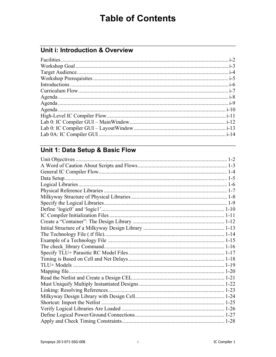
Table of Contents Unit i: Introduction & Overview Facilities ............................................................................................................................ i-2 Workshop Goal ................................................................................................................. i-3 Target Audience ................................................................................................................ i-4 Workshop Prerequisites .................................................................................................... i-5 Introductions ..................................................................................................................... i-6 Curriculum Flow ............................................................................................................... i-7 Agenda .............................................................................................................................. i-8 Agenda .............................................................................................................................. i-9 Agenda ............................................................................................................................ i-10 High-Level IC Compiler Flow ........................................................................................ i-11 Lab 0: IC Compiler GUI – MainWindow ....................................................................... i-12 Lab 0: IC Compiler GUI – LayoutWindow .................................................................... i-13 Lab 0A: IC Compiler GUI .............................................................................................. i-14 Unit 1: Data Setup & Basic Flow Unit Objectives ................................................................................................................ 1-2 A Word of Caution About Scripts and Flows .................................................................. 1-3 General IC Compiler Flow ............................................................................................... 1-4 Data Setup ........................................................................................................................ 1-5 Logical Libraries .............................................................................................................. 1-6 Physical Reference Libraries ........................................................................................... 1-7 Milkyway Structure of Physical Libraries ....................................................................... 1-8 Specify the Logical Libraries ........................................................................................... 1-9 Define ‘logic0’ and ‘logic1’ ........................................................................................... 1-10 IC Compiler Initialization Files ..................................................................................... 1-11 Create a “Container”: The Design Library .................................................................... 1-12 Initial Structure of a Milkyway Design Library ............................................................ 1-13 The Technology File (.tf file) ......................................................................................... 1-14 Example of a Technology File ...................................................................................... 1-15 The check_library Command ......................................................................................... 1-16 Specify TLU+ Parasitic RC Model Files ....................................................................... 1-17 Timing is Based on Cell and Net Delays ....................................................................... 1-18 TLU+ Models ................................................................................................................ 1-19 Mapping file ................................................................................................................... 1-20 Read the Netlist and Create a Design CEL .................................................................... 1-21 Must Uniquify Multiply Instantiated Designs ............................................................... 1-22 Linking: Resolving References ...................................................................................... 1-23 Milkyway Design Library with Design Cell .................................................................. 1-24 Shortcut: Import the Netlist ........................................................................................... 1-25 Verify Logical Libraries Are Loaded ............................................................................ 1-26 Define Logical Power/Ground Connections .................................................................. 1-27 Apply and Check Timing Constraints ............................................................................ 1-28 Synopsys 20-I-071-SSG-008 i IC Compiler 1
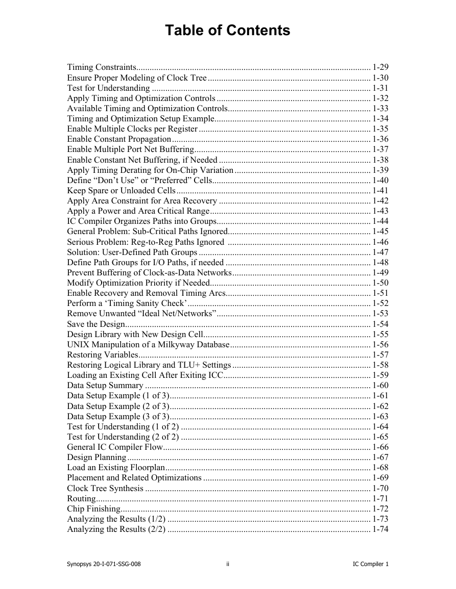
Table of Contents Timing Constraints......................................................................................................... 1-29 Ensure Proper Modeling of Clock Tree ......................................................................... 1-30 Test for Understanding .................................................................................................. 1-31 Apply Timing and Optimization Controls ..................................................................... 1-32 Available Timing and Optimization Controls ................................................................ 1-33 Timing and Optimization Setup Example ...................................................................... 1-34 Enable Multiple Clocks per Register ............................................................................. 1-35 Enable Constant Propagation ......................................................................................... 1-36 Enable Multiple Port Net Buffering ............................................................................... 1-37 Enable Constant Net Buffering, if Needed .................................................................... 1-38 Apply Timing Derating for On-Chip Variation ............................................................. 1-39 Define “Don’t Use” or “Preferred” Cells ....................................................................... 1-40 Keep Spare or Unloaded Cells ....................................................................................... 1-41 Apply Area Constraint for Area Recovery .................................................................... 1-42 Apply a Power and Area Critical Range ........................................................................ 1-43 IC Compiler Organizes Paths into Groups ..................................................................... 1-44 General Problem: Sub-Critical Paths Ignored................................................................ 1-45 Serious Problem: Reg-to-Reg Paths Ignored ................................................................ 1-46 Solution: User-Defined Path Groups ............................................................................. 1-47 Define Path Groups for I/O Paths, if needed ................................................................. 1-48 Prevent Buffering of Clock-as-Data Networks .............................................................. 1-49 Modify Optimization Priority if Needed........................................................................ 1-50 Enable Recovery and Removal Timing Arcs ................................................................. 1-51 Perform a ‘Timing Sanity Check’ .................................................................................. 1-52 Remove Unwanted “Ideal Net/Networks” ..................................................................... 1-53 Save the Design .............................................................................................................. 1-54 Design Library with New Design Cell ........................................................................... 1-55 UNIX Manipulation of a Milkyway Database ............................................................... 1-56 Restoring Variables ........................................................................................................ 1-57 Restoring Logical Library and TLU+ Settings .............................................................. 1-58 Loading an Existing Cell After Exiting ICC .................................................................. 1-59 Data Setup Summary ..................................................................................................... 1-60 Data Setup Example (1 of 3) .......................................................................................... 1-61 Data Setup Example (2 of 3) .......................................................................................... 1-62 Data Setup Example (3 of 3) .......................................................................................... 1-63 Test for Understanding (1 of 2) ..................................................................................... 1-64 Test for Understanding (2 of 2) ..................................................................................... 1-65 General IC Compiler Flow ............................................................................................. 1-66 Design Planning ............................................................................................................. 1-67 Load an Existing Floorplan ............................................................................................ 1-68 Placement and Related Optimizations ........................................................................... 1-69 Clock Tree Synthesis ..................................................................................................... 1-70 Routing ........................................................................................................................... 1-71 Chip Finishing ................................................................................................................ 1-72 Analyzing the Results (1/2) ........................................................................................... 1-73 Analyzing the Results (2/2) ........................................................................................... 1-74 Synopsys 20-I-071-SSG-008 ii IC Compiler 1
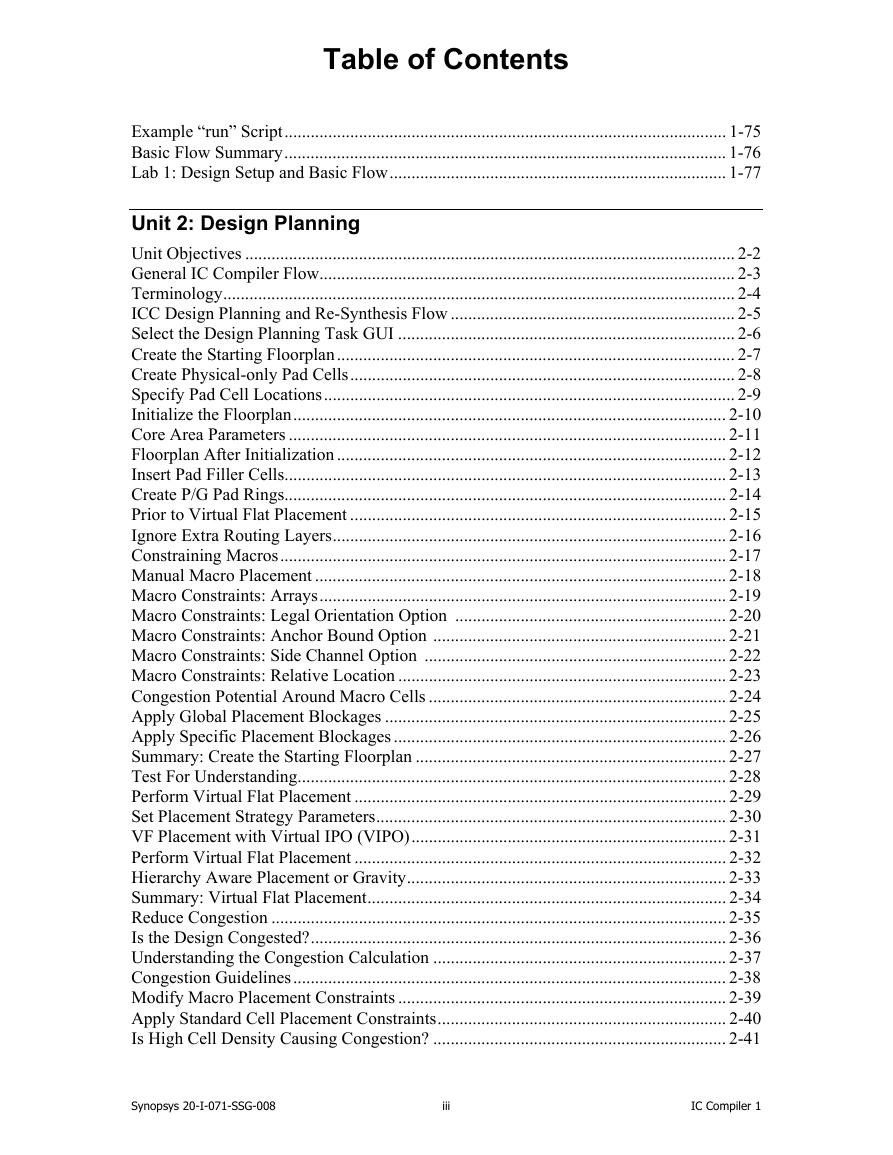
Table of Contents Example “run” Script ..................................................................................................... 1-75 Basic Flow Summary ..................................................................................................... 1-76 Lab 1: Design Setup and Basic Flow ............................................................................. 1-77 Unit 2: Design Planning Unit Objectives ................................................................................................................ 2-2 General IC Compiler Flow ............................................................................................... 2-3 Terminology ..................................................................................................................... 2-4 ICC Design Planning and Re-Synthesis Flow ................................................................. 2-5 Select the Design Planning Task GUI ............................................................................. 2-6 Create the Starting Floorplan ........................................................................................... 2-7 Create Physical-only Pad Cells ........................................................................................ 2-8 Specify Pad Cell Locations .............................................................................................. 2-9 Initialize the Floorplan ................................................................................................... 2-10 Core Area Parameters .................................................................................................... 2-11 Floorplan After Initialization ......................................................................................... 2-12 Insert Pad Filler Cells..................................................................................................... 2-13 Create P/G Pad Rings..................................................................................................... 2-14 Prior to Virtual Flat Placement ...................................................................................... 2-15 Ignore Extra Routing Layers .......................................................................................... 2-16 Constraining Macros ...................................................................................................... 2-17 Manual Macro Placement .............................................................................................. 2-18 Macro Constraints: Arrays ............................................................................................. 2-19 Macro Constraints: Legal Orientation Option .............................................................. 2-20 Macro Constraints: Anchor Bound Option ................................................................... 2-21 Macro Constraints: Side Channel Option ..................................................................... 2-22 Macro Constraints: Relative Location ........................................................................... 2-23 Congestion Potential Around Macro Cells .................................................................... 2-24 Apply Global Placement Blockages .............................................................................. 2-25 Apply Specific Placement Blockages ............................................................................ 2-26 Summary: Create the Starting Floorplan ....................................................................... 2-27 Test For Understanding.................................................................................................. 2-28 Perform Virtual Flat Placement ..................................................................................... 2-29 Set Placement Strategy Parameters ................................................................................ 2-30 VF Placement with Virtual IPO (VIPO) ........................................................................ 2-31 Perform Virtual Flat Placement ..................................................................................... 2-32 Hierarchy Aware Placement or Gravity ......................................................................... 2-33 Summary: Virtual Flat Placement .................................................................................. 2-34 Reduce Congestion ........................................................................................................ 2-35 Is the Design Congested? ............................................................................................... 2-36 Understanding the Congestion Calculation ................................................................... 2-37 Congestion Guidelines ................................................................................................... 2-38 Modify Macro Placement Constraints ........................................................................... 2-39 Apply Standard Cell Placement Constraints .................................................................. 2-40 Is High Cell Density Causing Congestion? ................................................................... 2-41 Synopsys 20-I-071-SSG-008 iii IC Compiler 1
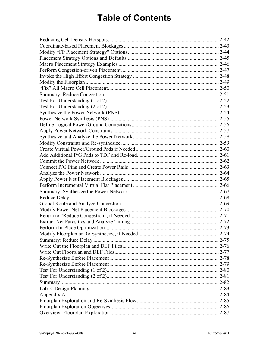
Table of Contents Reducing Cell Density Hotspots .................................................................................... 2-42 Coordinate-based Placement Blockages ........................................................................ 2-43 Modify “FP Placement Strategy” Options ..................................................................... 2-44 Placement Strategy Options and Defaults ...................................................................... 2-45 Macro Placement Strategy Examples ............................................................................ 2-46 Perform Congestion-driven Placement .......................................................................... 2-47 Invoke the High Effort Congestion Strategy ................................................................. 2-48 Modify the Floorplan ..................................................................................................... 2-49 “Fix” All Macro Cell Placement .................................................................................... 2-50 Summary: Reduce Congestion ....................................................................................... 2-51 Test For Understanding (1 of 2)..................................................................................... 2-52 Test For Understanding (2 of 2)..................................................................................... 2-53 Synthesize the Power Network (PNS) ........................................................................... 2-54 Power Network Synthesis (PNS) ................................................................................... 2-55 Define Logical Power/Ground Connections .................................................................. 2-56 Apply Power Network Constraints ................................................................................ 2-57 Synthesize and Analyze the Power Network ................................................................. 2-58 Modify Constraints and Re-synthesize .......................................................................... 2-59 Create Virtual Power/Ground Pads if Needed ............................................................... 2-60 Add Additional P/G Pads to TDF and Re-load .............................................................. 2-61 Commit the Power Network .......................................................................................... 2-62 Connect P/G Pins and Create Power Rails .................................................................... 2-63 Analyze the Power Network .......................................................................................... 2-64 Apply Power Net Placement Blockages ........................................................................ 2-65 Perform Incremental Virtual Flat Placement ................................................................. 2-66 Summary: Synthesize the Power Network .................................................................... 2-67 Reduce Delay ................................................................................................................. 2-68 Global Route and Analyze Congestion .......................................................................... 2-69 Modify Power Net Placement Blockages ...................................................................... 2-70 Return to “Reduce Congestion”, if Needed ................................................................... 2-71 Extract Net Parasitics and Analyze Timing ................................................................... 2-72 Perform In-Place Optimization ...................................................................................... 2-73 Modify Floorplan or Re-Synthesize, if Needed ............................................................. 2-74 Summary: Reduce Delay ............................................................................................... 2-75 Write Out the Floorplan and DEF Files ......................................................................... 2-76 Write Out Floorplan and DEF Files ............................................................................... 2-77 Re-Synthesize Before Placement ................................................................................... 2-78 Re-Synthesize Before Placement ................................................................................... 2-79 Test For Understanding (1 of 2)..................................................................................... 2-80 Test For Understanding (2 of 2)..................................................................................... 2-81 Summary ....................................................................................................................... 2-82 Lab 2: Design Planning .................................................................................................. 2-83 Appendix A .................................................................................................................... 2-84 Floorplan Exploration and Re-Synthesis Flow .............................................................. 2-85 Floorplan Exploration Objectives .................................................................................. 2-86 Overview: Floorplan Exploration .................................................................................. 2-87 Synopsys 20-I-071-SSG-008 iv IC Compiler 1
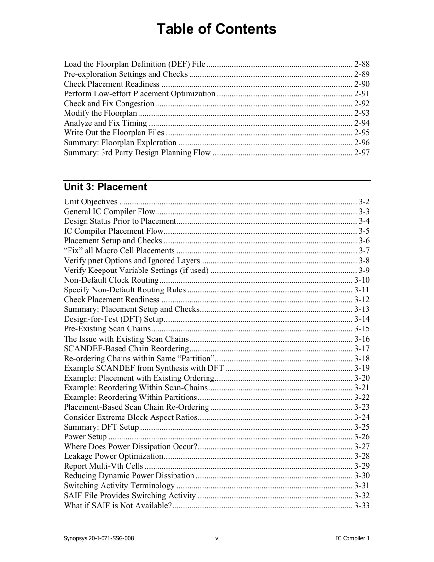
Table of Contents Load the Floorplan Definition (DEF) File ..................................................................... 2-88 Pre-exploration Settings and Checks ............................................................................. 2-89 Check Placement Readiness .......................................................................................... 2-90 Perform Low-effort Placement Optimization ................................................................ 2-91 Check and Fix Congestion ............................................................................................. 2-92 Modify the Floorplan ..................................................................................................... 2-93 Analyze and Fix Timing ................................................................................................ 2-94 Write Out the Floorplan Files ........................................................................................ 2-95 Summary: Floorplan Exploration .................................................................................. 2-96 Summary: 3rd Party Design Planning Flow .................................................................. 2-97 Unit 3: Placement Unit Objectives ................................................................................................................ 3-2 General IC Compiler Flow ............................................................................................... 3-3 Design Status Prior to Placement ..................................................................................... 3-4 IC Compiler Placement Flow ........................................................................................... 3-5 Placement Setup and Checks ........................................................................................... 3-6 “Fix” all Macro Cell Placements ..................................................................................... 3-7 Verify pnet Options and Ignored Layers ......................................................................... 3-8 Verify Keepout Variable Settings (if used) ..................................................................... 3-9 Non-Default Clock Routing ........................................................................................... 3-10 Specify Non-Default Routing Rules .............................................................................. 3-11 Check Placement Readiness .......................................................................................... 3-12 Summary: Placement Setup and Checks ........................................................................ 3-13 Design-for-Test (DFT) Setup ......................................................................................... 3-14 Pre-Existing Scan Chains ............................................................................................... 3-15 The Issue with Existing Scan Chains ............................................................................. 3-16 SCANDEF-Based Chain Reordering ............................................................................. 3-17 Re-ordering Chains within Same “Partition” ................................................................. 3-18 Example SCANDEF from Synthesis with DFT ............................................................ 3-19 Example: Placement with Existing Ordering ................................................................. 3-20 Example: Reordering Within Scan-Chains .................................................................... 3-21 Example: Reordering Within Partitions ......................................................................... 3-22 Placement-Based Scan Chain Re-Ordering ................................................................... 3-23 Consider Extreme Block Aspect Ratios ......................................................................... 3-24 Summary: DFT Setup .................................................................................................... 3-25 Power Setup ................................................................................................................... 3-26 Where Does Power Dissipation Occur? ......................................................................... 3-27 Leakage Power Optimization ......................................................................................... 3-28 Report Multi-Vth Cells .................................................................................................. 3-29 Reducing Dynamic Power Dissipation .......................................................................... 3-30 Switching Activity Terminology ................................................................................... 3-31 SAIF File Provides Switching Activity ......................................................................... 3-32 What if SAIF is Not Available? ..................................................................................... 3-33 Synopsys 20-I-071-SSG-008 v IC Compiler 1
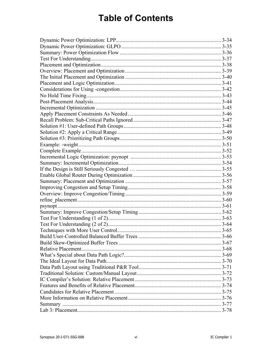
Table of Contents Dynamic Power Optimization: LPP ............................................................................... 3-34 Dynamic Power Optimization: GLPO ........................................................................... 3-35 Summary: Power Optimization Flow ............................................................................ 3-36 Test For Understanding.................................................................................................. 3-37 Placement and Optimization .......................................................................................... 3-38 Overview: Placement and Optimization ........................................................................ 3-39 The Initial Placement and Optimization ........................................................................ 3-40 Placement and Logic Optimization ................................................................................ 3-41 Considerations for Using -congestion ............................................................................ 3-42 No Hold Time Fixing ..................................................................................................... 3-43 Post-Placement Analysis ................................................................................................ 3-44 Incremental Optimization .............................................................................................. 3-45 Apply Placement Constraints As Needed ...................................................................... 3-46 Recall Problem: Sub-Critical Paths Ignored .................................................................. 3-47 Solution #1: User-defined Path Groups ......................................................................... 3-48 Solution #2: Apply a Critical Range .............................................................................. 3-49 Solution #3: Prioritizing Path Groups ............................................................................ 3-50 Example: -weight ........................................................................................................... 3-51 Complete Example ......................................................................................................... 3-52 Incremental Logic Optimization: psynopt .................................................................... 3-53 Summary: Incremental Optimization ............................................................................. 3-54 If the Design is Still Seriously Congested … ................................................................ 3-55 Enable Global Router During Optimization .................................................................. 3-56 Summary: Placement and Optimization ........................................................................ 3-57 Improving Congestion and Setup Timing ...................................................................... 3-58 Overview: Improve Congestion/Timing ........................................................................ 3-59 refine_placement ............................................................................................................ 3-60 psynopt ........................................................................................................................... 3-61 Summary: Improve Congestion/Setup Timing .............................................................. 3-62 Test For Understanding (1 of 2)..................................................................................... 3-63 Test For Understanding (2 of 2)..................................................................................... 3-64 Techniques with More User Control.............................................................................. 3-65 Build User-Controlled Balanced Buffer Trees .............................................................. 3-66 Build Skew-Optimized Buffer Trees ............................................................................. 3-67 Relative Placement ......................................................................................................... 3-68 What’s Special about Data Path Logic? ......................................................................... 3-69 The Ideal Layout for Data Path ...................................................................................... 3-70 Data Path Layout using Traditional P&R Tool.............................................................. 3-71 Traditional Solution: Custom/Manual Layout ............................................................... 3-72 IC Compiler’s Solution: Relative Placement ................................................................. 3-73 Features and Benefits of Relative Placement ................................................................. 3-74 Candidates for Relative Placement ................................................................................ 3-75 More Information on Relative Placement ...................................................................... 3-76 Summary ....................................................................................................................... 3-77 Lab 3: Placement............................................................................................................ 3-78 Synopsys 20-I-071-SSG-008 vi IC Compiler 1
分享到:
收藏