IEEE TRANSACTIONS ON COMMUNICATIONS, VOL. 42, NO. U314, FEBRUARYMARCWAPRIL 1994
1661
Reduced Complexity Symbol Detectors
with Parallel Structures for IS1 Channels
Javan Erfanian, Member, IEEE, Subbarayan Pasupathy, Fellow, IEEE,
and Glenn Gulak, Member, IEEE
Absrracr - The problem of practical realization of the optimal
fixed-delay symbol-by-symbol detection algorithm, which is op-
timum in the sense of minimizing the symbol error probability,
given a delay constraint D, is investigated. A fully-parallel struc-
ture is developed, and through systematic reformulations of the
algorithm, the computational requirements are reduced consider-
ably. In addition, the problems associated with a large dynamic
range such as overflow (or underffow) are (practically) removed.
A number of approximations are applied to this simplified paral-
lel symbol (SPS) detector that lead to the derivation of subop-
timal detectors. One such suboptimal detector is shown to be the
same as the minimum-metric Viterbi detector. A brief comparis-
on of the SPS detector and the Viterbi detector shows that the
former has a slightly better performance at low values of signal-
to-noise ratio (SNR) and the latter performs a smaller number of
computations (particularly) at higher values of SNR; otherwise,
the two detectors are comparable in performance and complexi-
ty.
I. INTRODUCTION
An increasing demand for high data rate transmission over
bandlimited channels with severe intersymbol interference
(ISI) has resulted in a fluny of activity over the last two de-
cades to develop improved methods of equalization 111. Since
error probability is the most important performance measure
in such applications, it is of interest to develop practical VLSI
implementable receivers which optimize some measures
directly related to probability of error. Two important criteria
in this regard are: maximum likelihood sequence estimation
(MLSE) and minimum probability of symbol error.
An important breakthrough came with the derivation of
maximum-likelihood receivers for channels with
jinite
memory. Taking advantage of the fact that the effective range
of IS1 is actually finite. Chang and I-Iancock derived a sequen-
tial procedure [2], in which the number of computations in-
creased only linearly (rather than exponentially) with the mes-
sage length. Following [21, Abend and Fritchman [3] derived
the optimum fixed-delay ‘symbol-by-symbol’ detector, which
is optimum in the sense of minimizing the symbol error proba-
bility given a fixed delay constraint, D (Le. given aU the previ-
ous as well as D succeeding received samples). This is
Paper approved by C.P. Jeremy Tzeng, the Editor for VLSI in
Communicahons of the IEEE Communications Swety. Manuscnpt received
October 1. 1990 and rewsed November IS, 1991. The research was supported
by grants from the Natural Saences and Englneenng Research Coma1
(NSERC) of Canada. Some of the results have been reported ln IEEE Paafic
k m c‘onf. on Commun., Computers, & Signal Processing, Victona, B.C.,
Canada. June 89. Canadian Cod. on Elec. & Computer Engg., Montreal,
Canada, Sept.89, and GLOBECOM’90, San bego, Dec.90.
Authors are wth the Depattment of Electrical and Computer Engmeenng,
simpler than the optimum compound detector [4,5], in that the
symbol estimation can be carried out before the entire data se-
quence is received. Nevertheless, neither this nor related
simplifications, as in [61. were thought of as practical pro-
cedures and researchers have pointed out the reasons [7-91.
Unlike optimal symbol detection, the procedure that has re-
ceived tremendous attention in the last two decades is the Vi-
terbi algorithm (VA), which was originally introduced in 1967
for maximum-likelihood decoding of convolutional codes
[lo], and, after its optimality in the sense of MLSE was real-
ized, it was applied to signaling on IS1 channels [8,11,12].
While the structural aspects of MLSE (or the related VA)
have received a great deal of attention [13-181, the criterion
and/or algorithms based on the minimum probability of sym-
bol error have not received the same scrutiny. The main pur-
pose of the present paper is to examine an algorithm which
minimizes symbol error probability with the objective of
developing parallel-structure implemenmtions with low com-
plexity. We focus on the practical realization of the optimal
fixed-delay symbol-by-symbol detection algorithm derived in
[31. First, the algorithm is mapped onto a fully-parallel struc-
ture suitable for VLSI implementlition. Then, a number of
simplifications are introduced, through systematic reformula-
tions of the algorithm. that avoid the computation of exponen-
rials ‘and reduce (or possibly eliminate) the number of muiti-
plications to be performed. All this is achieved at a price
which seems acceptable in practice. In Section IV, a number
of suboptimal design considerations are discussed and a few
suboptimal symbol-by-symbol detectors are introduced. In
Section V, the simplified parael symbol (SPS) detector is
compared to the Viterbi detector, where it is shown that a
suboptimal SPS detector is identical to the minimum-metric
Viterbi detector.
11. OPTIMAL SYMBOL-BY-SYMBOL DETECTION
A. The System Model
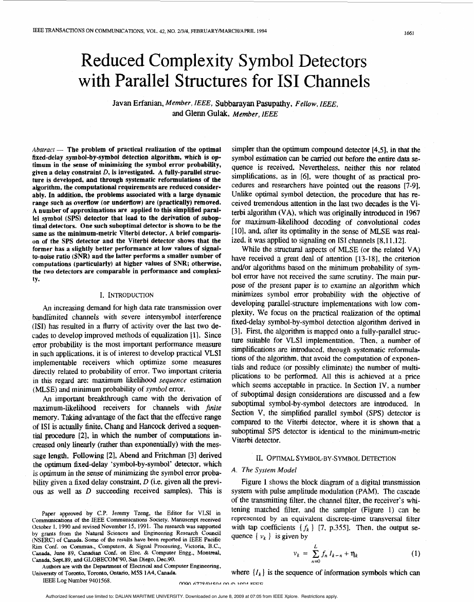
Figure 1 shows the block diagram of a digital tr‘msmission
system with pulse ‘amplitude modulation (PAM). The cascade
of the transmitting filter. the channel filter, the receiver’s whi-
tening matched filter. and the sampler (Figure 1) can be
represented by ;in equivalent discrete-time transvend filter
with tap coefficients (fk ] [7, p.3551. Then. the output se-
quence ( vk ) is given by
L
(1)
where (Ik] is the sequence of information symbols which can
vk = x . f n l k - n f q k
n=O
University of Toronto, Toronto, Ontano, M5S 1 A4, Canada
IEEELog Number 9401568.
nnon L - I - I Q K M ~ ~ A nn A ~ n n ~
teen
Authorized licensed use limited to: DALIAN MARITIME UNIVERSITY. Downloaded on June 8, 2009 at 07:05 from IEEE Xplore. Restrictions apply.
�
1662
IEEE TRANSACTIONS ON COMMUNICATIONS, VOL. 42, NO. 21314, FEBRUARYMARCHIAPRE 1994
Fig. 1. Baseband digital transmission system.
on any value ik drawn from an M-symbol alphabet
t$e
(It =+I in the binary case), L is the effective length of the
channel dispersion, and ( q k ) are independent, identically dis-
tributed Gaussian random variables with zero mean and vari-
ance N o 12.
The specific problem is to provide a delayed estimate of
the transmitted symbol I k - D , given the observed received se-
quence v i , v 2 , . . . , V k , where D is the chosen delay con-
straint, according to some optimality criterion.
B. The Algorithm
We consider the optimal symbol-by-symbol detection al-
gorithm under a fixed delay constmint, developed by Abend
and Fritchman [3] and as presented in [71. The algorithm IS
optimum in the sense of minimizing the probability of a sym-
hol error. in compdson with all detectors which depend on
the same number of received samples.
Let v , , v2, ..., vg be the observed received sequence, where
k > D 2L.l As is well known, minimization of symbol error
probability is equivalent to MAP estimation. Hence, the algo-
probabilities
nthm
( V k , ..., V i ) for the M possible symbol VdUeS
p ( ! k - ~ =Ik-’
and chooses the one with the largest probability [7, p.3871.
posteriori
computes
the
The MAP estimate of the information symbol at time
a
X: -D , denoted I,, , is given by
= arg { max
1t-D
I,
1, D * I
. . . C uk(Ik? .. , I M ) I
n
A
(2)
In (2), the expression arg ( ,G ( a )
that satisfies the function G ( - ) , the term
1 k - n
} is equal eo the value of
( ) is the
Ik-D
summation over all possible values of I k , and the function
uk ( . ) is obtained recursively from
h
4
A
U k ( I k I ..., I k - D ) = P ( V k
A
h
I1k,
A
. . . 7 I k - L ) ‘(I,)
h
U k - l ( l k - l , ..., I k - D - 1 )
A
(3)
/’bo-,
where P ( I k ) is the a priori probability of the information
symbol I k and p ( . ) denotes the probability density function of
the received sample conditioned on the possible values of the
information symbols and is given by
1 The algonthm for the case D < L (also given m 131 ) is sundar to the w e
D 2 L presented m this paper, except that it considers L (rather than D) most
recent symbols for the recursion.
C. The Computational Complexity
Using (4), the recursion in (3) can be replaced, for statisti-
cally independent, qui-probable (i.e., P(I, ) =PI ) input data,
by
U‘k(;k, ., i k - D ) = U L ( i k , ...) T k - D ) x ( =/PI
) k
x f , [ k - J ) 2 1 N o 1
A
1
L
I”0
I\
1
1
=eXp -(Vk-
L.,
x
u ’ k - l ( I k - 1 .
..., I k - D - 1 )
(4)
Using (3, the initial vdue for the recursion in (4), is obtained
from
ub+l(iD+l?...?il )=exp { - x ( V k - x & f i k - J ) 2 / N 0
D+1
k=l
L
/=o
1 (7)
The MAP estimate of the information symbol, at time k - D , is
then given by
1k-D = arg ( m a . ‘ ’
1, *
I,
I*-,+,
U’k ( I k , ..., 1k-D ) }
n
A
(8)
L
For simplicity, we only consider M = 2 (binary signaling) in
this paper. The results can be simply generalized to any alpha-
bet size. In (6), for each received sample vk (or, alternatively,
for each symbol estimate), 2L+1 exponentials need to be com-
puted. The exponentials cannot be replaced by their ex-
ponents, because they are added rather than multiplied. In ad-
+- 2L+1 multiplications required
dition, there is a total of 2”’
for the estimation of each symbol, ;is dictated by (6). We have
Ik-, l2
for which there may be different ways of implementation in-
cluding using a table look-up. There are also 2O additions, as
suggested by (6), and 2 ( 2’
- 1 ) additions, as required by (8).
Furthermore, there is one binary comparison needed in (8).
The operations required for the eshmation of each symbol are
summarized in the first column of Table 1.
ignored the operations involved in obtaining ( v k - c
The intimidating computational burden of the above algo-
rithm is apparent from Table 1. The procedure involved is
particularly complicated due to the large number of the slow
and composite operations of exponentiation and multiplication
required for the estimation of each symbol. In addition, there
is a large dynamic range associated with the computation of
exponentials. In a typical floating-point representation, this
I “ )
A
Authorized licensed use limited to: DALIAN MARITIME UNIVERSITY. Downloaded on June 8, 2009 at 07:05 from IEEE Xplore. Restrictions apply.
�
ERFANIAN et al.: REDUCED COMPLEXITY SYMBOL DETECTORS
leads to ovefiow (or underflow) problems. A practical reali-
zation of this algorithm, which is the focus of this paper, is not
possible without challenging its computational burden.
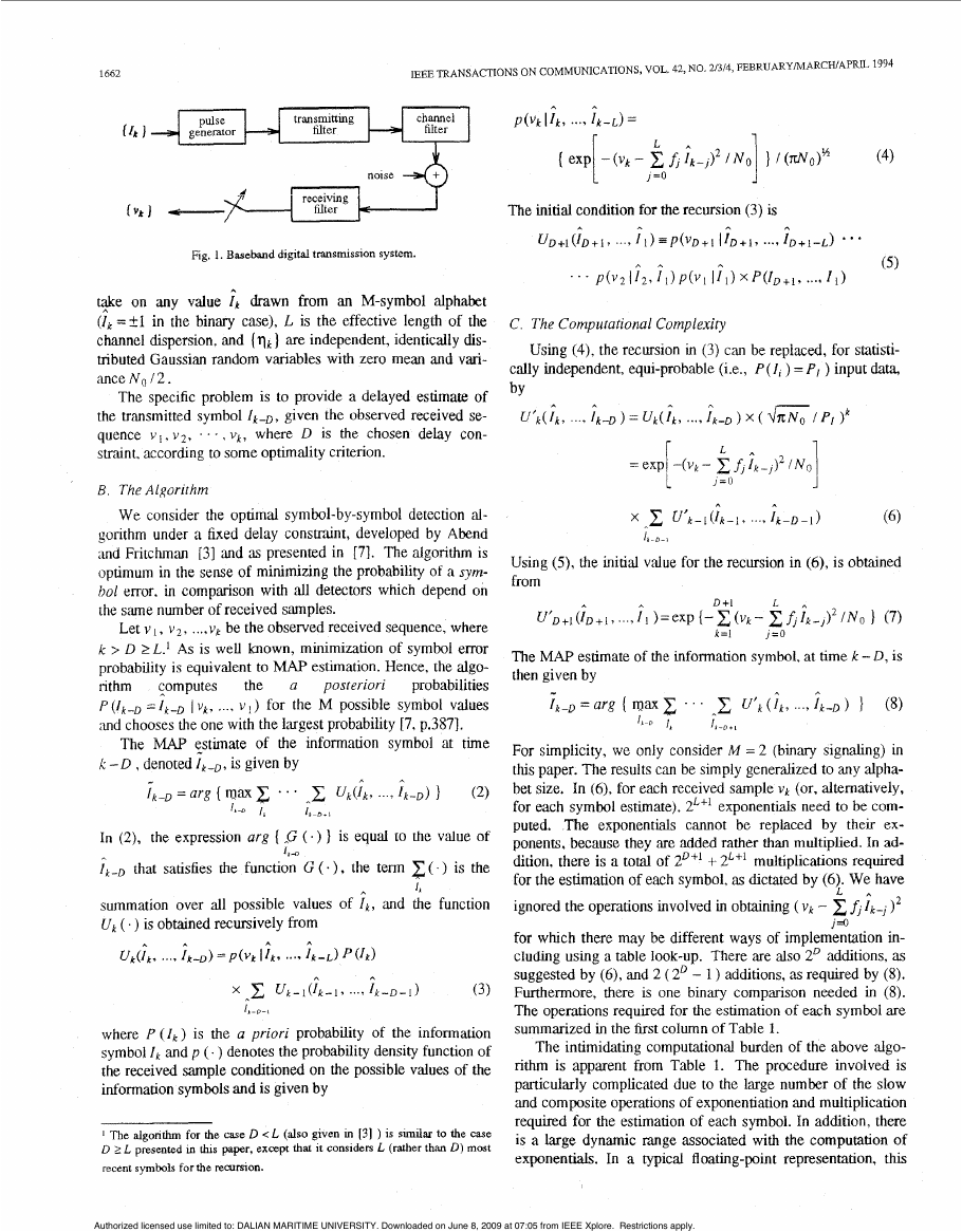
COMPLEXITY OF SYMBOL DETECTORS
TABLE 1
I Exuonent'n
Multipl'n
Addit'n
I/
2~
II - II
2 N + 2 Y -
3 N - 2
2.5N+2
--
-
3Y
I - I
I
2Y
Slwiv'gsq. I --
11 (D-L)xY I ( D - L ) x Y
I I
111. SIMPLIFIED PARALLEL SYMBOL D E T E ~ O R
A Parallel Structure
To exploit the structure inherent in the algorithm 'and to
take full advantage of its parallelism ,and reguhity, we follow
a procedure (as in [19] ) towards a design that is suitable for
VLSI implementation [20-231. First, the recursive algorithm
is mapped onto a p,dlel ,array structure.
To simplify the notation in (6), let
i = O
In (9) and (IO). the time index k is chosen to match the time
index of the received data v k and the index j is the decimal
value. in the range j = O,1. . . . ,2'" - 1 , corresponding to
the hintmy representation of a specific path (or sequence)
mong the paths given by all possible values of the D + 1 most
recent information symbols. At time k, the index j can be ob-
tained from
where the function < x > is equal to x for positive x and zero
otherwise. The 2'+' paths, at anylygive? time k, coArrespond to
possible @ I ? S of the set { I k - D , I k - D + I , ..., l k } (e.g. if
a l
n = l . then { I k ,
} = ( k 1 , f l 1, rtnd j = o , 1.2. 3).
Then. with N 2' , the algorithm defined by (6)-(8) can
1k-l
l
be rewritten as follows.
[:::
1663
(1lC)
rk-D = ar8 ( rt)a
xi" , 'E1X;] ]
lt-0
j = N
Note that the expression in brackets in (1 la) is the same in
(i2a)
the computation of both X i i and X i l + Let
Yf =xi + X ~ + N , i=O,1, . . . , N - l
Then. (1 la) can be rewritten as
- ,2N-1
= Y[$.J
x e*'"'
, j = o , 1,
(12b)
where the floor function la] denotes the greatest imeger not
greater than a.
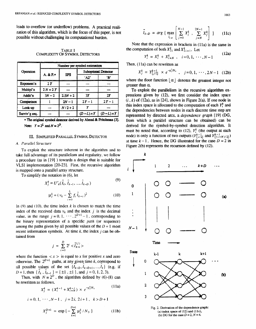
To exploit the parailelism in the recursive algorithm ex-
pressions given by (12), we first consider the index space
(i , k) of (12a), as in [24], shown in Figure 2(a). If one node in
this index space is allocated to the computation of each l':
and
the dependencies between nodes in each discrete time step are
represented by directed arcs, a dependence graph [191 (DG,
from which a parallel suucture can be obtained) can be
derived for the symbol-by-symbol detection algorithm. It
must be noted that, according to (12), Y! (the output at each
node) is only a function of two outputs ( Y t l , ; ~ and Y~;:N,,~J)
at hme k - 1 . Hence, the DG illustrated for the case D = 2 in
Figure 2(b) represents the recursion defined by (12).
k r
1
2
...
k+D
m
* . a
0
1
N- 1
S t a a I
0 0
T i -
.-I"."
0
k- 1
k
k+l ...
Fig. 2. Derivation of the dependence graph:
(a)lndexspaceof(12)and(llc),
(b) DG for the case D = 2, N = 4.
�
1664
IEEE TRANSACTIONS ON COMMUNICATIONS, VOL 42, NO 21314, FEBRUARYIMARCWAPRL 1994
Let us define a state vector Sk, given by one set amongst all
the possible values of the D most recent information symbols,
D + I
(19N
a ,
where
min* (xf , x: = mint xf[ , x: ) + qf,,
(19b)
and @f,, is given by (18). Using (13) in (llb) and (12b) gives
Xf+’ = C j ~ : , iz0.1, * * . , 2 N - 1
D + I
( 1 9 ~ )
k = l
x, k - -yll/2j
k - 1 +pf;, i = 0 , 1, . . . , 2 N - I ; k > D + 1 (19d)
Note, from (18) and (19), hat the knowledge of the noise
variance, N~ / 2, is now used in the computation of
only.
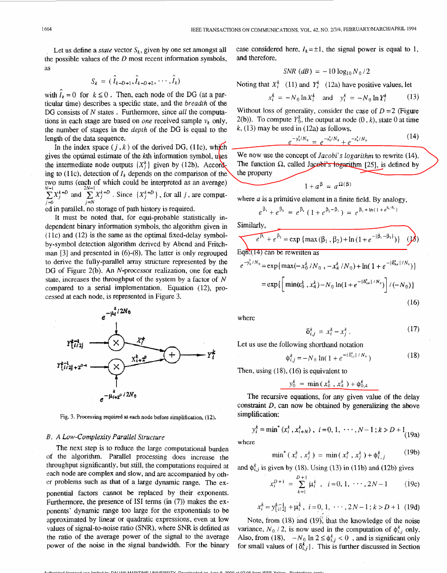
Also, from (I@, - N o In 2 2 @! ; < 0 , and is signiiicant onlv
for small values of I
1. This is further discussed in Section
Authorized licensed use limited to: DALIAN MARITIME UNIVERSITY. Downloaded on June 8, 2009 at 07:05 from IEEE Xplore. Restrictions apply.
�ERFANIAN et ai.: REDUCED COMPLEXITY SYMBOL DETECTORS
IV. A significant simplification of the algorithm (19) occurs
when only yf is computed at every node ( j , k ) and the factor
is tabulated explicitly as a function of 1 at,, I . Figure 4
$:,,
shows the resulting simplification in the processing required at
each node.
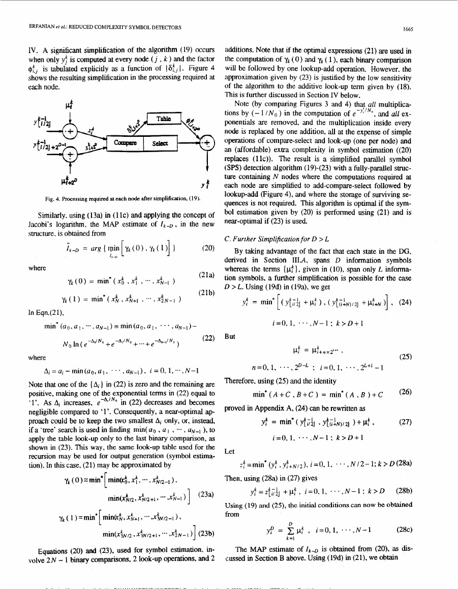
k
Y f
Fig. 4. Processmg required at each node after simplification. (19).
Similarly, using (13a) in (1 IC) and applying the concept of
Jacobi’s logarithm, the MAP estimate of I k - D , in the new
structure, is obtained from
f k - D = urR(win[ykt~).yk(l)] I
(20)
where
1, -D
In Eqn.(21),
1665
additions. Note that if the optmal expressions (21) are used in
the computation of y k ( 0 ) and y k ( 1 ), each binary comparison
will be followed by one lookup-add operation. However, the
approximation given by (23) is justified by the low sensitivity
of the algorithm to the additive look-up term given by (18).
This is further discussed in Section IV below.
Note (by comparing Figures 3 and 4) that all multiplica-
tions by (- 1 /No ) in the computation of e-””’,
and all ex-
ponentials are removed, and the multiplication inside every
node is replaced by one addition, ‘ail at the expense of simple
operations of compare-select and look-up (one per node) and
an (affordable) extra complexity in symbol estimation ((20)
replaces (llc)). The result is a simplified parallel symbol
(SPS) detection algorithm (19)-(23) with a fully-parallel struc-
ture containing N nodes where the computations required at
each node are simplified to add-compare-select followed by
lookup-add (Figure 4), and where the storage of surviving se-
quences is not required. This algorithm is optimal if the sym-
bol estimation given by (20) is performed using (21) and is
near-optlmal if (23) is used.
C. Further Simplification for D > L
By taking advantage of the fact that each state in the DG,
derived in Section IIIA, spans D information symbols
whereas the terms (pf: }, given in (lo), span only L informa-
tion symbols, a further simplification is possible for the case
D > L. Using (19d) in (194, we get
Y;k = min* [(Yes;] + d
(24)
9 ( Y f ( I : N ) / Z ]
$+N )] 9
min*~a~,a~,--..a~_l)~min(ao,al,
- . - , u N - l ) -
- W N o + e-A,/No + ... + e-Av-j/No
No b ( e
)
(22)
But
i = O , l , ..., N-1; k > D + 1
k
-
PI - P1+nxz‘”
k
9
where
AI = a, - inin (ao, a , . . . , aN-I ) , I = 0, 1, ... , N-1
-A.lNo
Note that one of the (Al ) in (22) is zero and the remaining are
positive, making one of the exponential terms in (22) equal to
‘1’. As AI increases. e
in (22) decreases and becomes
negligible compared to ‘1’. Consequently, a near-optimal ap-
proach could be to keep the two smallest Ai only, or, instead,
if a ‘tree’ search is used in finding min( Q O , a 1 , .-- , U N - ~ ), to
apply the table look-up only to the last binary comparison, as
shown in (23). This way, the same look-up tzzble used for the
recursion may be used for output generation (symbol estima-
tion). In this case, (21) may be approximated by
Equations (20) and (23), used for symbol estimation, in-
volve 2 N - 1 binary comparisons, 2 look-up operations, and 2
n=O, 1, . * . , P - L ; 1=0,1* . .. ,2L+‘-1
Therefore, using (25) and the identity
(25)
m i n * ( A + C , B + C ) = min*(A , B ) + C
(26)
proved in Appendix A, (24) can be rewritten as
Yf = min* ( YfiJJ Yf(rf~)/zJ 1-k d
(27)
i=0,1, * - . , N - l : k > D + l
Let
$=minu (yf , ~ f + ~ / ~ ) ,
i=O, 1, . . . , N 12- 1;k > D(28a)
Then, using (28a) in (27) gives
k - 1
y I - Z ~ ~ / Z J +p:, i=0,1, . . * , N - l : k > D
k -
(28b3
Using (19) ‘and (25), the initial conditions can now be obtained
from
D
yf = x p f , i=0,1,
N-1
.
a
*
,
(28c)
k =I
The MAP estimate of 1k-D is obtained f ” (20), as dis-
cussed in Section B above. Using (19d) in (21), we obtain
Authorized licensed use limited to: DALIAN MARITIME UNIVERSITY. Downloaded on June 8, 2009 at 07:05 from IEEE Xplore. Restrictions apply.
�
1666
IEEE TRANSACTIONS ON COMMUNICATIONS, VOL. 42, NO. 21314, FEBRUARYMARCHIAPRU 1994
'select' operation is not counted explicitly since it occurs in
parallel with the look-up operation.
Nevertheless, considering that a multiplication is a few
times more complex than an addition, a binary comparison, or
a look-up operation. and that the complexity of an exponentia-
tion is yet several times that of a multiplicahon, the substantial
reduction in overall complexity is apparent. To this, one can
add the other additional benefits: The (serious) problems asso-
ciated with a large dynamic r&ge, such as overflow or
underflow, are (practically) avoided by replacing the summa-
tion of exponentials by values comparable to their exponents;
and, finally, as stated earlier, the exploitation of the parallel-
ism inherent in the algorithm has resulted in the derivation of
a parallel structure, suitable for VLSI implementation, with a
speed-up factor of N compared to a serial implementation.
IV. MORE SUBOPTIMAL DETECTORS
Simulation results show that the SPS detection algorithm
derived in Section I11 is quite robust to uncertainty in our
knowledge of the noise variance N o / 2 and. generally, it is re-
latively insensitive to the size of the look-up table (18) espe-
c d l y at moderate to high values of SNR. The significance of
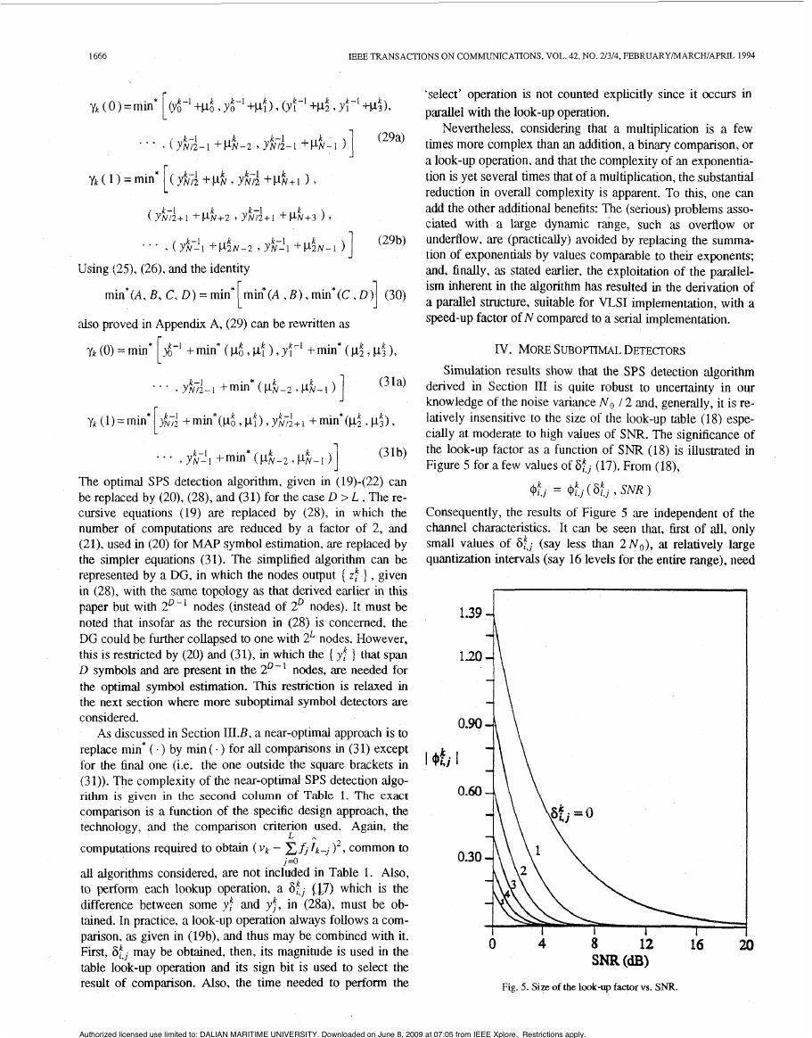
the look-up factor as a function of S N R (18) is illustrated in
Figure 5 for a few values of SkJ (17). From (l8),
@:., = 4$,
(St, 9 SNR )
Consequently, the results of Figure 5 are independent of the
channel characteristics. It can be seen that, first of all, only
at relatively large
small values of S$ (say less than 2 ~ ~ )
quantization intervals (say 16 levels for the entire range), need
,
1.39
1.20
I bkj
Fig. 5. Size of the look-up faaorvs. SNR.
Using (29, (26). and the identity
J
*l
min*(A, B, C, D ) = min min*(A , B ) , min*(C,
also proved in Appendix A, (29) can be rewritten as
y k (0) = min $-' + min* ( p.6 , pf 1, yi-' + min* ( p; , pi 1,
(3 la)
*i
. . . , y&;i-l +min* ( p i p z
1 ) ]
. . . , yhL! 1 + min" ( pk-2 , pN- k
(31b)
The optimal SPS detection algorithm, given in (19)-(22) can
be replaced by (20), (28), and (31) for the case D > L . The re-
cursive equations (19) are replaced by (28), in which the
number of computations are reduced by a factor of 2, and
(21), used in (20) for MAP symbol estimation, are replaced by
the simpler equations (31). The simplified algorithm can be
represented by a DG, in which the nodes output { z! 1 , given
in (28), with the same topology as that derived earlier in this
paper but with 2D-' nodes (instead of 2' nodes). It must be
noted that insofar as the recursion in (28) is concemed, the
DG could be further collapsed to one with 2L nodes. However,
thts IS restricted by (20) and (31), in which the { y:
] that span
D symbols and are present in the 2 D - 1 nodes, are needed for
the optimal symbol estimation. This restnction is relaxed in
the next section where more suboptimal symbol detectors are
considered.
As discussed in Section III.B, a near-optimal approach is to
replace min* ( . ) by min ( . ) for all comparisons in (3 1) except
for the final one (i.e. the one outside the square brackets in
(31)). The complexity of the near-optimal SPS detection algo-
rithm is given in the second column of Table 1. The exact
companson is a function of the specific design approach, the
technology, and the comparison criterion used. Again, the
computations required to obtain (vk - EA 1k-J )', common to
all algorithms considered, are not included in Table 1. Also,
to perform each lookup operation, a St, (17) which is the
difference between some yf and yf, in (28a), must be ob-
tained. In practice, a look-up operation always follows a com-
parison, as given in (19b), and thus may be combined with it.
First, St, may be obtained, then, its magnitude is used in the
table look-up operation and its sign bit is used to select the
result of comparison. Also, the time needed to perform the
J = o
L
-
Authorized licensed use limited to: DALIAN MARITIME UNIVERSITY. Downloaded on June 8, 2009 at 07:05 from IEEE Xplore. Restrictions apply.
�
ERFANIAN et al.: REDUCED COMPLEXITY SYMBOL DETECTORS
1667
to be tabulated (hence a small look-up table) and, secondly,
the look-up factor becomes negligible for moderate to high
values of SNR.
This can lead to the derivation of suboptimal detectors.
One such detector, referred t~ zis SubopfimJ Deeaor 'Al',
avoids the look-up operation (Le. ignores ( $f,, ) ) in the re-
cursion (28) and reduces the processing required at each node
to add-compare-select (ACS) only. Another one, Suboptimal
Detector 'B', avoids the look-up operation both in the recur-
sion (28) and in the symbol estimation (20),(31). In other
words. each function min'(.) is replaced by the function
min(.).
To derive a simple algorithm for Suboptimal Detector 'B',
we proceed as follows. Using (20), replacing min" ( - ) by
min( .) in (31). and interchanging the arguments of the com-
parison. we obtain
I,-D=arg{min rmin(yd-1 ,yi;.j )+min(pd ,pf ),
I,,
min(y:-',yK+l
) + m i n ( ~ 2 . ~ 3 ) , ,
k
k
where (28a) is used in the second line of (32).
We recall that whereas ( y f ) , given in (a), span the D
most recent information symbols, (zft 1, given in (28a), only
span the D - 1 most recent information symbols. However,
,der replacing min* ( . ) by min (. ) in (28a), it can be noted
khat 2; is the minimum of yI" and y : + ~ / 2 which differ only in
f k - D . Therefore, $very time if' is computed, the argument of
the comparison, 1k-D. must be stored. In other words, the
reduction by a factor of 2 in area (or folding of 'space'), by
mapping the 2' members of the set ( y/j , y: , . . . , yN-I
}
onto the ZD-' members of the set ( zd , z: , . . . , zi/2-1 1, is
accompanied by the introduction of 2D-1 surviving symbol es-
timates for Ik-D, each associated with one of (zf } .
Considering (25), the same approach, given in Section
1II.C that led to the mapping of the set ( yd , yt , . . . , yft-l ]
- , zk12-1 1 may be applied repeated-
onto the set ( z t , z: , * e
ly,
for a
to obtain a set
] with only 2L components. Each map-
( qt , qf ,
ping introduces a surviving symbol associated with every
member in the set and the D -L mappings introduce 2L sur-
total of D - L
,
times,
k
viving sequences. each of length D -L. Therefore, the algo-
rithm for Suboptimal Detector *B', obtained by applying the
mapping used to derive (28) and (32) D - L times, is as fol-
lows.
_ k - l + pf: . &;,+2"-'
Yfi = - 1 - 1
l l l U l \ YL1/2j
1, 4
i=O,l, * * + , 2 L - l ; k > L + l
t &+2'
k
),
i33a)
L+I
d+' = rrlin( c p:
-
l k - D = arg (Fin( & 7 qf 7
k = l
1 ,
1
I r a
L + I
c P!+2L )
* * * 9 q$"-I ) 1
k=l
(33b)
(33c)
Equation (33) can be represented by the DG derived in Sec-
tion IIIA (Figure 2(b)) with 2L nodes, where each node-com-
putes (33a). Not only is qk computed, but the surviving f k - L is
also stored at each node. In (33c), ik-D is obtained from the
surviving sequence which corresponds to the node with
min(q6 , qf , . . . , &-I
though
this algorithm,
derived for the case D > L, is also valid for D = L may be
verified by replacing min' ( . ) by min ( . ) in (19),(21).
). That
A hybrid of the optimal SPS detector and Suboptimal
Detector 'B', referred to as Suboptimal Detector ' M ' , may
also be derived. This can be obtained directly from the optimal
SPS detection algorithm (20),(28),(31) through an approach
similar to the one used to derive the 'B' algorithm. The only
difference is that min' ( . ) and min ( e ) are taken to be equal in
the symbol estunation (20),(31) but not in the recursion (28).
The result is an algorithm which is the same as (33), except
that min( .) is replaced by min* ( . ) in (334 and (33b). The
complexities of Suboptimal Detectors 'A2' 'and
'B' are
displayed in Table 1.
The insignificance of the look-up factor with increasing
S N R suggests that the performance of these suboptimal detec-
tors should approach optimal performance as S N R increases.
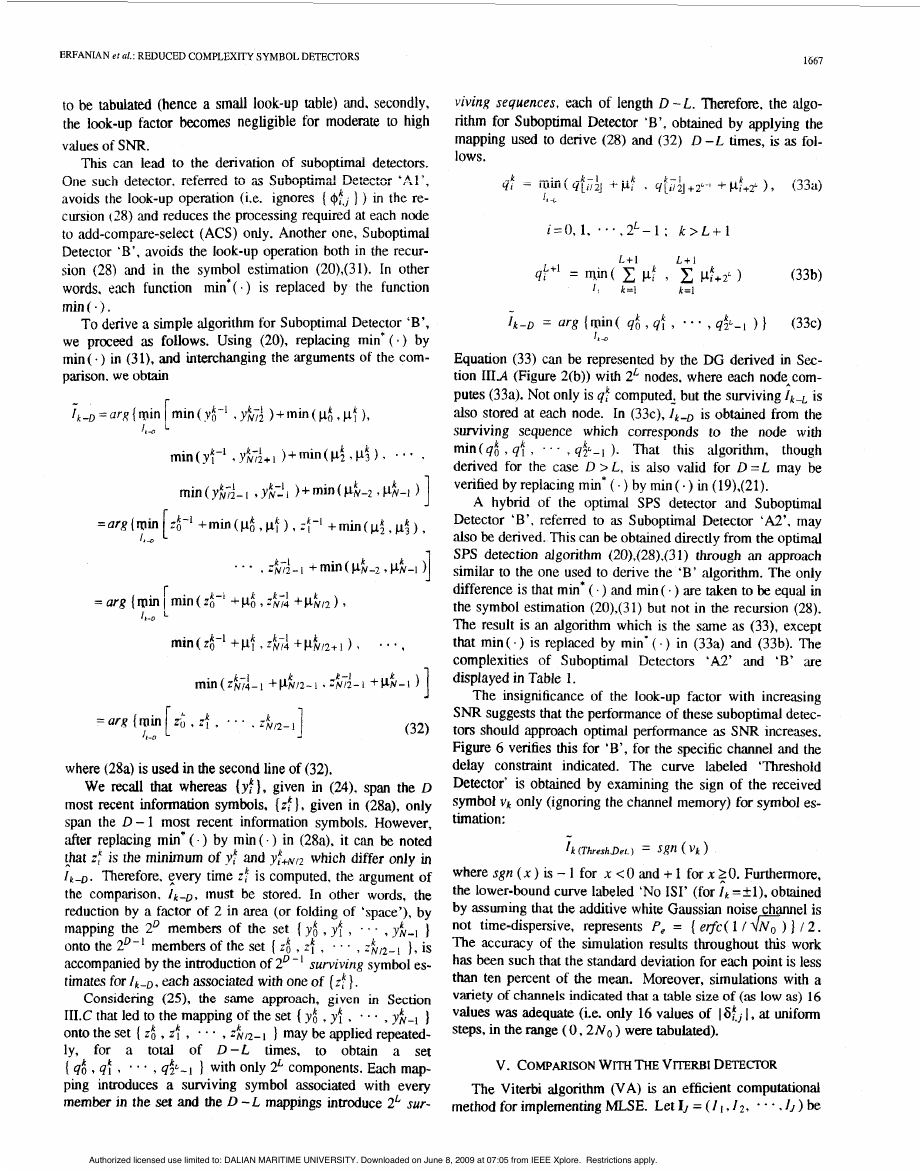
Figure 6 verifies this for 'B', for the specific channel and the
delay constraint indicated. The curve labeled
'Threshold
Detector' is obtained by ex,amining the sign of the received
symbol vk Only (ignoring the channel memory) for Symbol es-
timation:
-
I k (ThreshDef.) = sgn ( vk )
where sgn ( x ) is - 1 for x < 0 and + 1 for n 0. Furthermore,
the lower-bound curve labeled 'No ISI' (for l k =+1), obtained
not time-dispersive, represents P, = ( e$c( 1 / 6) 1 / 2 .
by assuming that the additive white Gaussian noise channel is
The accuracy of the simulation results throughout this work
has been such that the standard deviation for each point is less
than ten percent of the mean. Moreover, simulations with a
variety of channels indicated that a table size of (as low 'as) 16
values was adequate (Le. only 16 values of ISfj I, at uniform
steps, in the range ( 0, 2 N o ) were tabulated).
V. COMPARISON WITH THE VI'ERBI DETECTOR
The Viterbi algorithm (VA) is an efficient computational
method for implementing MLSE. Let IJ = ( I I , 12, * * * , I, ) be
Authorized licensed use limited to: DALIAN MARITIME UNIVERSITY. Downloaded on June 8, 2009 at 07:05 from IEEE Xplore. Restrictions apply.
�
1668
IEEE TRANSACTIONS ON COMMUNICATIONS, VOL. 42, NO. 21314, FEBRUARYMARCHIAPRIL 1994
I
0.0051
I
0
I
2
4
T
I
6
- \
I
I
8
0
~m (a)
1
-
1
I
I
2
1
1
In practice, the variable delay involved in symbol detection
is replaced by a fixed delay constraint through truncating the
length of the surviving sequences to D most recent symbols. If
D is sufficiently large, there is a high probability that all the
surviving ‘paths’ at time k agree up to time k - D [8,26]; if
they do not agree, a decision (according to some sthategy) is
forced on the symbol 1k-D. It is reported that the loss in perfor-
mance, due to this suboptimal decision procedure, is negligi-
ble if D 2 5 L 171. In practice, values of D in the range
( S L to 10L 1, depending on the values of SNR, are used.
Furthermore. in the VA, there are different strategies to
‘force’ a decision, in case the surviving sequences at time k do
not agree up to time k -D [8]. A few of these strategies are
the ‘majority decision’ rule (choosing the symbol suggested
by the majority of the surviving sequences), the ‘minimum
memc’ rule (choosing the symbol suggested by the path with
minimum metric), and the ‘arbitmy selection’ rule (choosing
the symbol suggested by an arbitrary path).
The recursion in (35) can be represented by the Viterbi
trellis [261 which has the same structure as the SPS detector’s
DG (Figure 2(b)). The Viterbi trellis may also be considered
as its DG [191 and may be used directly for its VLSI imple-
mentation [141. It consists of 2L nodes where the processing
at each node is the add-compare-select (ACS) given in (35).
Based on this representation, (35) may be rewritten as
i = O , l , * * * , 2 L - l : k > L + l
441-1 = lQin( c pf , c ! d + 2 L )
L + l
L+I
1 ,
k = l
k=l
(36b)
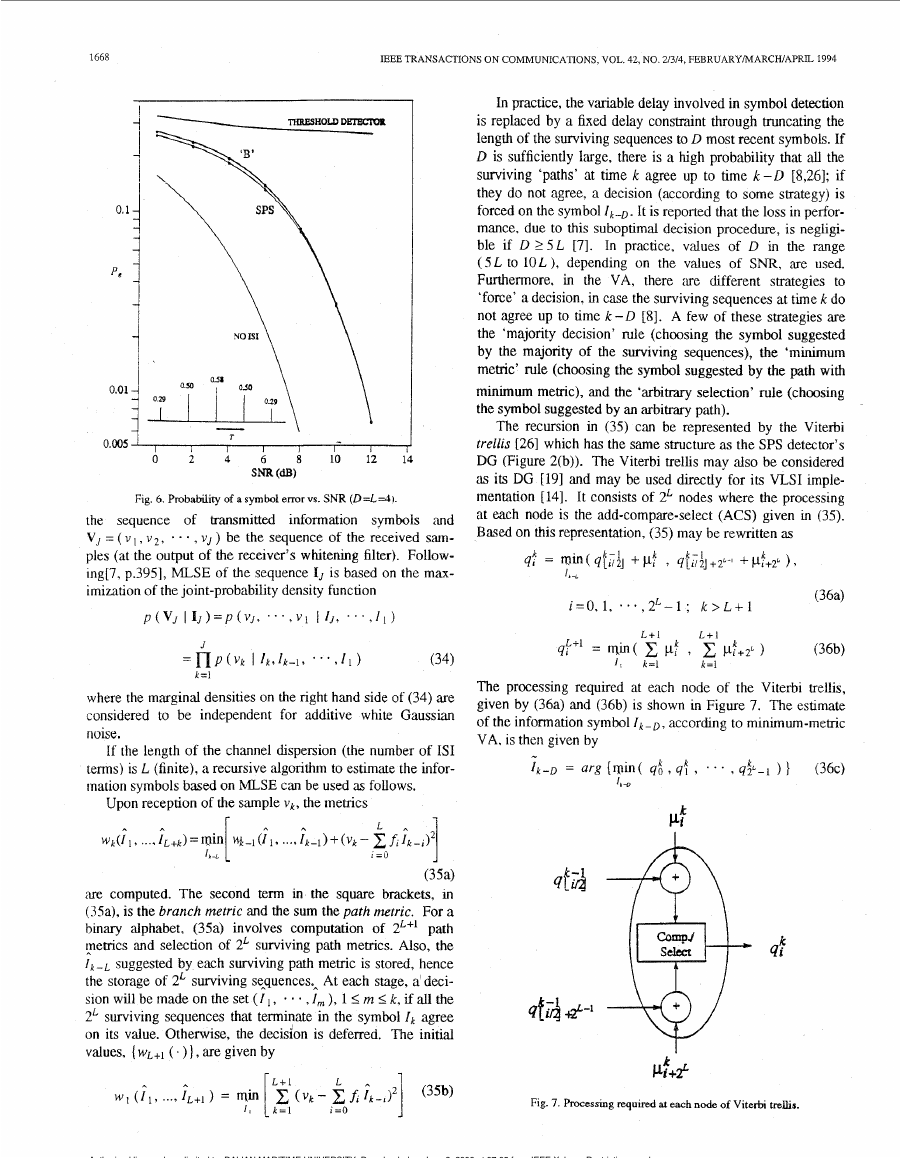
The processing required at each node of the Viterbi trellis,
given by (36a) and (36b) is shown in Figure 7. The estimate
according to minimum-metric
of the information symbol I,-,,
VA. is then given by
.,
Ik-D = arg {win( q i t 4: 3
Ir -D
’ ..
3 q$-1 ) 1
( 3 6 ~ )
Pf
4:
Pf+P
Fig. 7. hcessing required at each node of Viterbi trelhs.
Fig. 6. Probability of a symbol errorvs. SNR (D=L=4]
thansmitted
the sequence of
information symbols ‘and
V, = ( v I , v 2 , . . . , V J ) be the sequence of the received sam-
ples (at the output of the receiver’s whitenmg filter). Follow-
ing[7, p.3951, MLSE of the sequence IJ is based on the maax-
imimtion of the joint-probability density function
~ ( V J
~ I J ) = P ( v J , “ ‘ , v i
I IJ, . . . , I I )
= n P ( V k I l k , l k - L , * ‘ * , l I )
J
k=l
(34)
where the marginal densities on the right hand side of (34) are
considered to be independent for additive white Gaussian
noise.
If the length of the channel dispersion (the number of IS1
terms) is L (finite), a recursive algorithm to estimate the infor-
mation symbols based on MLSE can be used as follows.
Upon reception of the sample v k , the metrics
P A
I =o L
1
A
lb -L
(35a)
are computed. The second term in the square brackets, in
(Ma), is the branch metric and the sum the path metric. For a
binary alphabet, (3%) involves computation of 2L+1 path
pemcs and selection of 2L surviving path memcs. Also, the
I k - L suggested by each surviving path metric is stored, hence
the storage of 2L surviving sequences, At each stage, a deci-
,I,,,), 1 I m < k , if all the
sion will be made on the set ( I I ,
2L surviving sequences that terminate in the symbol Ik agree
on its value. Otherwise, the decision is deferred. The initial
values, ( wL+l ( . ) 1, are given by
wk(l 1 , .... I L + k ) = rain V+~(I I , ..., I ~ - ~ ) + ( v ~
-
A
fi I ~ - ~ ) ~
Authorized licensed use limited to: DALIAN MARITIME UNIVERSITY. Downloaded on June 8, 2009 at 07:05 from IEEE Xplore. Restrictions apply.
�


 2023年江西萍乡中考道德与法治真题及答案.doc
 2012年重庆南川中考生物真题及答案.doc
 2013年江西师范大学地理学综合及文艺理论基础考研真题.doc
 2020年四川甘孜小升初语文真题及答案I卷.doc
 2020年注册岩土工程师专业基础考试真题及答案.doc
 2023-2024学年福建省厦门市九年级上学期数学月考试题及答案.doc
 2021-2022学年辽宁省沈阳市大东区九年级上学期语文期末试题及答案.doc
 2022-2023学年北京东城区初三第一学期物理期末试卷及答案.doc
 2018上半年江西教师资格初中地理学科知识与教学能力真题及答案.doc
 2012年河北国家公务员申论考试真题及答案-省级.doc
 2020-2021学年江苏省扬州市江都区邵樊片九年级上学期数学第一次质量检测试题及答案.doc
 2022下半年黑龙江教师资格证中学综合素质真题及答案.doc