NCS8803 HDMI-to-eDP Converter w/ scaler
NCS8803
Application Note
Application note V0.92
1 硬件设计注意事项
1.1 电源
NCS8803 电源需要 3.3V 和 1.2V 供电。建议 3.3V 最大输出电流在 200mA 以上,1.2V
最大输出电流在 800mA 以上(Scaler to 4K/60HZ),以上参数只含 NCS8803 功耗。
PWD 不需要特殊处理,按照参考原理图接下拉 4.7K 电阻到地即可。
1.2 布线
由于 eDP 和 HDMI 信号是高速信号,建议信号差分阻抗控制在 100ohm±10%。eDP
信号避免使用过孔,为了方便 PCB layout,eDP lane 支持 lane 顺序交换和 eDP lane 的 P/N
极性交换。lane 顺序交换可以通过调整 0x75 设备地址的 0x84 和 0x85 寄存器与 layout lane
顺序对应;lane P/N 极性交换可以通过调整 0x70 设备地址的 0x73 寄存器的低 4 位与 layout
lane 极性对应。
1.3 初始化配置
NCS8803 需要上电对寄存器做初始化配置后才能正常工作,可以使用主控或外挂 MCU
通过 IIC 总线对 NCS8803 进行配置。
2 寄存器列表
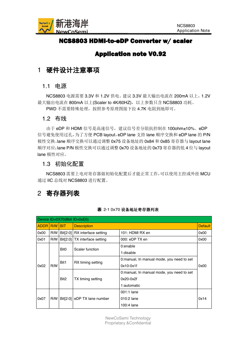
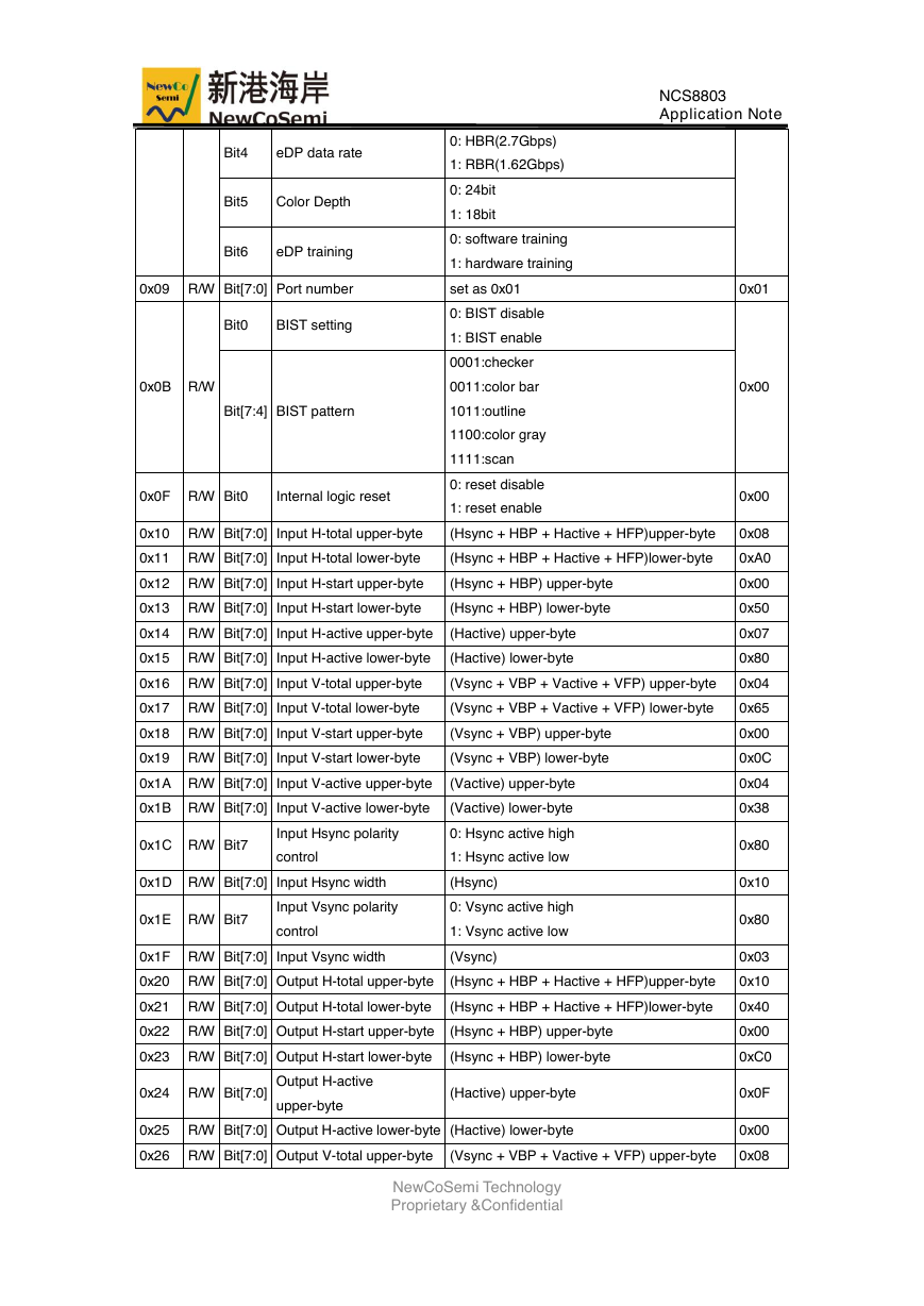
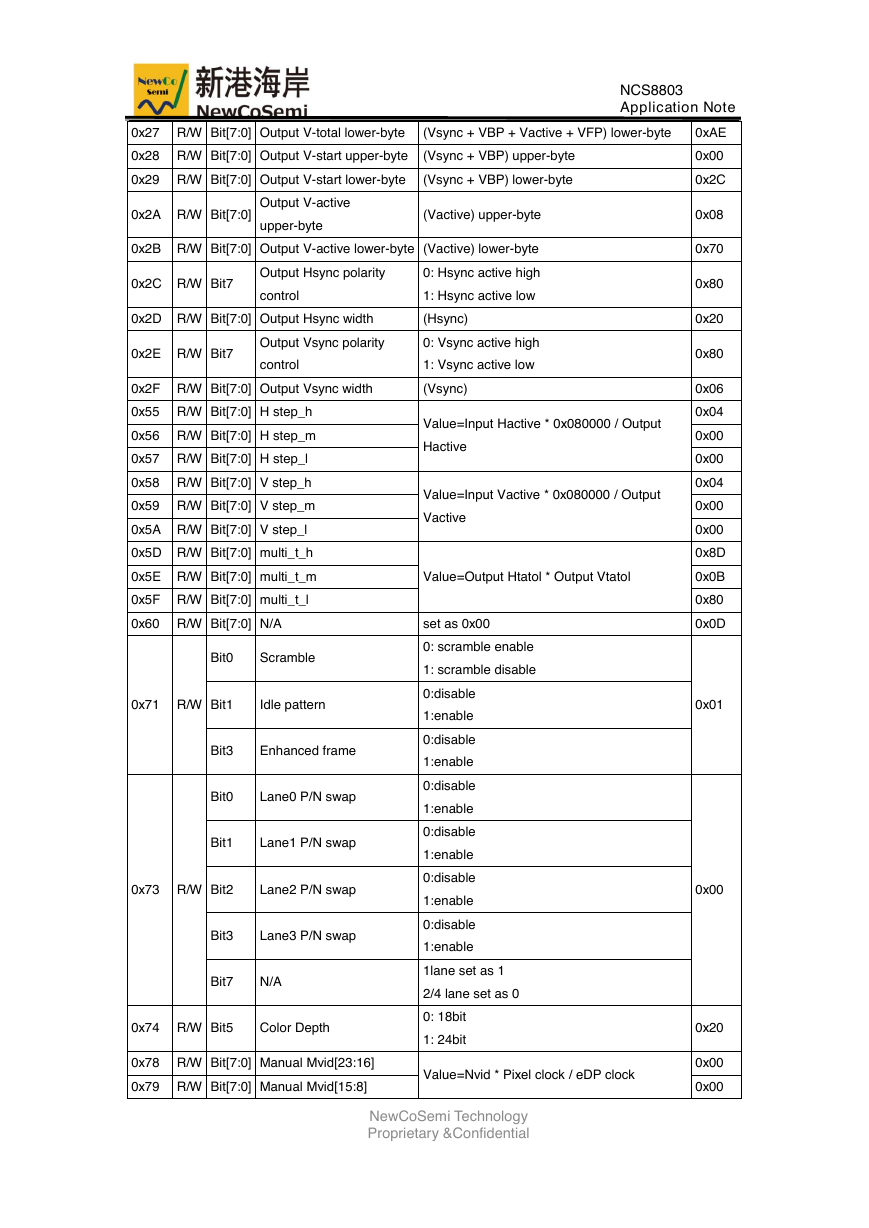
表 2-1 0x70 设备地址寄存器列表
Device ID=0X70(8bit ID=0xE0)
ADDR R/W BIT
Description
0x00 R/W Bit[2:0] RX interface setting
101: HDMI RX en
0x01 R/W Bit[2:0] TX interface setting
000: eDP TX en
Bit0
Scaler function
0:enable
1:disable
Default
0x00
0x00
0x02 R/W
Bit1
RX timing setting
0:manual, In manual mode, you need to set
0x10-0x1f
0x00
0:manual, In manual mode, you need to set
Bit2
TX timing setting
0x20-0x2f
1:automatic
001:1 lane
0x07 R/W Bit[2:0] eDP TX lane number
010:2 lane
0x14
100:4 lane
NewCoSemi Technology
Proprietary &Confidential
�
NCS8803
Application Note
Bit4
eDP data rate
Bit5
Color Depth
Bit6
eDP training
0: HBR(2.7Gbps)
1: RBR(1.62Gbps)
0: 24bit
1: 18bit
0: software training
1: hardware training
0x09 R/W Bit[7:0] Port number
set as 0x01
0x01
Bit0
BIST setting
0x0B R/W
0: BIST disable
1: BIST enable
0001:checker
0011:color bar
Bit[7:4] BIST pattern
1011:outline
0x0F R/W Bit0
Internal logic reset
1100:color gray
1111:scan
0: reset disable
1: reset enable
0x00
0x00
0x10 R/W Bit[7:0] Input H-total upper-byte
(Hsync + HBP + Hactive + HFP)upper-byte
0x08
0x11 R/W Bit[7:0] Input H-total lower-byte
(Hsync + HBP + Hactive + HFP)lower-byte
0xA0
0x12 R/W Bit[7:0] Input H-start upper-byte
(Hsync + HBP) upper-byte
0x13 R/W Bit[7:0] Input H-start lower-byte
(Hsync + HBP) lower-byte
0x14 R/W Bit[7:0] Input H-active upper-byte
(Hactive) upper-byte
0x15 R/W Bit[7:0] Input H-active lower-byte
(Hactive) lower-byte
0x00
0x50
0x07
0x80
0x16 R/W Bit[7:0] Input V-total upper-byte
(Vsync + VBP + Vactive + VFP) upper-byte
0x04
0x17 R/W Bit[7:0] Input V-total lower-byte
(Vsync + VBP + Vactive + VFP) lower-byte
0x65
0x18 R/W Bit[7:0] Input V-start upper-byte
(Vsync + VBP) upper-byte
0x19 R/W Bit[7:0] Input V-start lower-byte
(Vsync + VBP) lower-byte
0x1A R/W Bit[7:0] Input V-active upper-byte
(Vactive) upper-byte
0x1B R/W Bit[7:0] Input V-active lower-byte
(Vactive) lower-byte
0x1C R/W Bit7
Input Hsync polarity
0: Hsync active high
control
1: Hsync active low
0x1D R/W Bit[7:0] Input Hsync width
(Hsync)
0x1E R/W Bit7
Input Vsync polarity
0: Vsync active high
control
1: Vsync active low
0x1F R/W Bit[7:0] Input Vsync width
(Vsync)
0x00
0x0C
0x04
0x38
0x80
0x10
0x80
0x03
0x20 R/W Bit[7:0] Output H-total upper-byte
(Hsync + HBP + Hactive + HFP)upper-byte
0x10
0x21 R/W Bit[7:0] Output H-total lower-byte
(Hsync + HBP + Hactive + HFP)lower-byte
0x40
0x22 R/W Bit[7:0] Output H-start upper-byte
(Hsync + HBP) upper-byte
0x23 R/W Bit[7:0] Output H-start lower-byte
(Hsync + HBP) lower-byte
0x24 R/W Bit[7:0]
Output H-active
upper-byte
(Hactive) upper-byte
0x25 R/W Bit[7:0] Output H-active lower-byte (Hactive) lower-byte
0x00
0xC0
0x0F
0x00
0x26 R/W Bit[7:0] Output V-total upper-byte
(Vsync + VBP + Vactive + VFP) upper-byte
0x08
NewCoSemi Technology
Proprietary &Confidential
�
0x27 R/W Bit[7:0] Output V-total lower-byte
(Vsync + VBP + Vactive + VFP) lower-byte
NCS8803
Application Note
0xAE
0x28 R/W Bit[7:0] Output V-start upper-byte
(Vsync + VBP) upper-byte
0x29 R/W Bit[7:0] Output V-start lower-byte
(Vsync + VBP) lower-byte
0x2A R/W Bit[7:0]
Output V-active
upper-byte
(Vactive) upper-byte
0x2B R/W Bit[7:0] Output V-active lower-byte (Vactive) lower-byte
0x2C R/W Bit7
Output Hsync polarity
0: Hsync active high
control
1: Hsync active low
0x2D R/W Bit[7:0] Output Hsync width
(Hsync)
0x2E R/W Bit7
Output Vsync polarity
0: Vsync active high
control
1: Vsync active low
0x2F R/W Bit[7:0] Output Vsync width
(Vsync)
0x55 R/W Bit[7:0] H step_h
0x56 R/W Bit[7:0] H step_m
0x57 R/W Bit[7:0] H step_l
0x58 R/W Bit[7:0] V step_h
0x59 R/W Bit[7:0] V step_m
0x5A R/W Bit[7:0] V step_l
0x5D R/W Bit[7:0] multi_t_h
Value=Input Hactive * 0x080000 / Output
Hactive
Value=Input Vactive * 0x080000 / Output
Vactive
0x5E R/W Bit[7:0] multi_t_m
Value=Output Htatol * Output Vtatol
0x5F R/W Bit[7:0] multi_t_l
0x60 R/W Bit[7:0] N/A
set as 0x00
Bit0
Scramble
0: scramble enable
1: scramble disable
0x71 R/W
Bit1
Idle pattern
Bit3
Enhanced frame
Bit0
Lane0 P/N swap
Bit1
Lane1 P/N swap
0x73 R/W
Bit2
Lane2 P/N swap
Bit3
Lane3 P/N swap
Bit7
N/A
0x74 R/W Bit5
Color Depth
0x78 R/W Bit[7:0] Manual Mvid[23:16]
0x79 R/W Bit[7:0] Manual Mvid[15:8]
0:disable
1:enable
0:disable
1:enable
0:disable
1:enable
0:disable
1:enable
0:disable
1:enable
0:disable
1:enable
1lane set as 1
2/4 lane set as 0
0: 18bit
1: 24bit
Value=Nvid * Pixel clock / eDP clock
NewCoSemi Technology
Proprietary &Confidential
0x00
0x2C
0x08
0x70
0x80
0x20
0x80
0x06
0x04
0x00
0x00
0x04
0x00
0x00
0x8D
0x0B
0x80
0x0D
0x01
0x00
0x20
0x00
0x00
�
0x7A R/W Bit[7:0] Manual Mvid[7:0]
0x7B R/W Bit[7:0] Manual Nvid[23:16]
0x7C R/W Bit[7:0] Manual Nvid[15:8]
Nvid set as 0x008000
0x7D R/W Bit[7:0] Manual Nvid[7:0]
0x7E R/W Bit0
Manual Mvid/Nvid enable
0:disable
1:enable
0x8A RO Bit[7:0] Auto Mvid[23:16]
0x8B RO Bit[7:0] Auto Mvid[15:8]
0x8C RO Bit[7:0] Auto Mvid[7:0]
0x8D RO Bit[7:0] Auto Nvid[23:16]
0x8E RO Bit[7:0] Auto Nvid[15:8]
0x8F RO Bit[7:0] Auto Nvid[7:0]
0xA0 R/W Bit0
EDID ADDR
0xA1 R/W Bit0
EDID DATA
Bit0
HPD manual
0xA3 R/W
Bit4
HPD manual enable
0: HPD=L
1: HPD=H
0:disable
1:enable
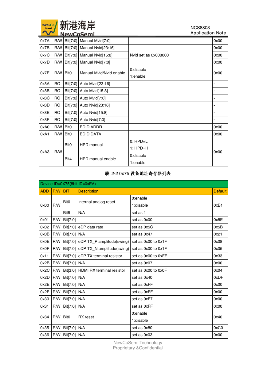
表 2-2 0x75 设备地址寄存器列表
Device ID=0X75(8bit ID=0xEA)
ADD R/W BIT
Description
0x00 R/W
Bit0
Internal analog reset
Bit5
N/A
0x01 R/W Bit[7:0]
0x02 R/W Bit[7:0] eDP data rate
0x0B R/W Bit[7:0] N/A
0:enable
1:disable
set as 1
set as 0x00
set as 0x5C
set as 0x47
0x0E R/W Bit[7:0] eDP TX_P amplitude(swing) set as 0x00 to 0x1F
0x0F R/W Bit[7:0] eDP TX_N amplitude(swing) set as 0x00 to 0x1F
0x11 R/W Bit[7:0] eDP TX terminal resistor
set as 0x00 to 0xFF
0x2B R/W Bit[7:0] N/A
set as 0x07
0x2C R/W Bit[3:0] HDMI RX terminal resistor
set as 0x00 to 0x0F
0x2D R/W Bit[7:0] N/A
0x2E R/W Bit[7:0] N/A
0x2F R/W Bit[7:0] N/A
0x30 R/W Bit[7:0] N/A
0x31 R/W Bit[7:0] N/A
0x34 R/W Bit6
RX reset
0x35 R/W Bit[7:0] N/A
0x36 R/W Bit[7:0] N/A
set as 0x40
set as 0xFF
set as 0xFF
set as 0xF7
set as 0xFF
0:enable
1:disable
set as 0x80
set as 0x03
NewCoSemi Technology
Proprietary &Confidential
NCS8803
Application Note
0x00
0x00
0x00
0x00
0x00
-
-
-
-
-
-
0x00
0x00
0x00
Default
0xB1
0x8E
0x5B
0x21
0x08
0x05
0x33
0x00
0x04
0xDF
0x00
0x00
0x00
0x00
0x40
0xC0
0x00
�
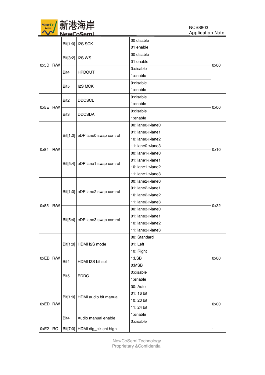
Bit[1:0] I2S SCK
Bit[3:2] I2S WS
Bit4
HPDOUT
Bit5
I2S MCK
Bit2
DDCSCL
Bit3
DDCSDA
Bit[1:0] eDP lane0 swap control
Bit[5:4] eDP lana1 swap control
Bit[1:0] eDP lane2 swap control
Bit[5:4] eDP lane3 swap control
0x5D R/W
0x5E R/W
0x84 R/W
0x85 R/W
Bit[1:0] HDMI I2S mode
0xEB R/W
Bit4
HDMI I2S bit sel
Bit5
EDDC
Bit[1:0] HDMI audio bit manual
0xED R/W
Bit4
Audio manual enable
00:disable
01:enable
00:disable
01:enable
0:disable
1:enable
0:disable
1:enable
0:disable
1:enable
0:disable
1:enable
00: lane0->lane0
01: lane0->lane1
10: lane0->lane2
11: lane0->lane3
00: lane1->lane0
01: lane1->lane1
10: lane1->lane2
11: lane1->lane3
00: lane2->lane0
01: lane2->lane1
10: lane2->lane2
11: lane2->lane3
00: lane3->lane0
01: lane3->lane1
10: lane3->lane2
11: lane3->lane3
00: Standard
01: Left
10: Right
1:LSB
0:MSB
0:disable
1:enable
00: Auto
01: 16 bit
10: 20 bit
11: 24 bit
1:enable
0:disable
0xE2 RO Bit[7:0] HDMI dig_clk cnt high
NewCoSemi Technology
Proprietary &Confidential
NCS8803
Application Note
0x00
0x00
0x10
0x32
0x00
0x00
-
�
0xE3 RO Bit[7:0] HDMI dig_clk cnt low
0xE4 RO Bit[7:0] HDMI RX_clk cnt high
0xE5 RO Bit[7:0] HDMI RX_clk cnt low
3 软件配置说明
3.1 寄存器配置说明
NCS8803
Application Note
-
-
-
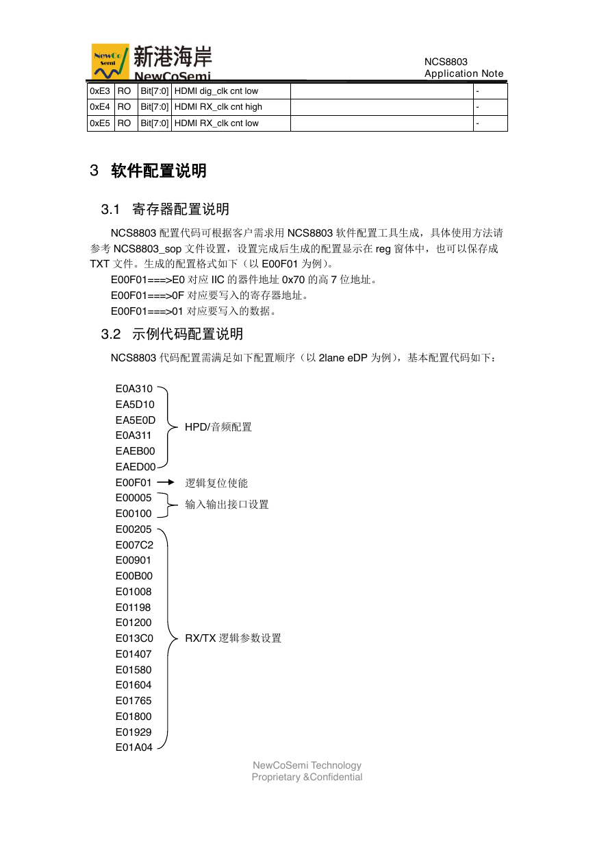
NCS8803 配置代码可根据客户需求用 NCS8803 软件配置工具生成,具体使用方法请
参考 NCS8803_sop 文件设置,设置完成后生成的配置显示在 reg 窗体中,也可以保存成
TXT 文件。生成的配置格式如下(以 E00F01 为例)。
E00F01===>E0 对应 IIC 的器件地址 0x70 的高 7 位地址。
E00F01===>0F 对应要写入的寄存器地址。
E00F01===>01 对应要写入的数据。
3.2 示例代码配置说明
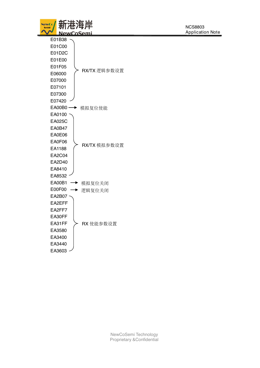
NCS8803 代码配置需满足如下配置顺序(以 2lane eDP 为例),基本配置代码如下:
E0A310
EA5D10
EA5E0D
E0A311
EAEB00
EAED00
E00F01
E00005
E00100
E00205
E007C2
E00901
E00B00
E01008
E01198
E01200
E013C0
E01407
E01580
E01604
E01765
E01800
E01929
E01A04
HPD/音频配置
逻辑复位使能
输入输出接口设置
RX/TX 逻辑参数设置
NewCoSemi Technology
Proprietary &Confidential
�
NCS8803
Application Note
RX/TX 逻辑参数设置
模拟复位使能
RX/TX 模拟参数设置
模拟复位关闭
逻辑复位关闭
RX 使能参数设置
NewCoSemi Technology
Proprietary &Confidential
E01B38
E01C00
E01D2C
E01E00
E01F05
E06000
E07000
E07101
E07300
E07420
EA00B0
EA0100
EA025C
EA0B47
EA0E06
EA0F06
EA1188
EA2C04
EA2D40
EA8410
EA8532
EA00B1
E00F00
EA2B07
EA2EFF
EA2FF7
EA30FF
EA31FF
EA3580
EA3400
EA3440
EA3603
�
4 应用说明
4.1 调试说明
NCS8803
Application Note
NCS8803 应用时推荐按照如下顺序进行调试。
(1)首先保证电压和时钟可以正常工作,IIC 可以正常通信。
(2)判断 TX 端和 panel training 是否成功。
设置为 hard training 模式时可以读取器件地址 0x70 的 0x81 寄存器的值来做参考判断,
当读取到 0x07(对应 eDP 为 1lane)和 0x77(对应 eDP 为 2lane)时认为 NCS8803 和
panel 的 training 交互成功。
(3)判断 RX 端是否可以正确接收源参数。
RX 参数可以通过读取器件地址 0x75 的 0xE2-0xE5 寄存器的值来确认输入源是否正常
锁定,0xE2-0xE5 对应的源参数具体说明请查阅寄存器表相关说明,锁定正常时 0xE2 值和
0xE4 的值固定并相等,0xE3 值和 0xE5 值会稳定锁定到某个值附近,偏差在±2 范围内。
4.2 Scaler 设置
NCS8803 使用 scaler 功能时请参考如下步骤修改对应寄存器配置。
(1)设备地址 0x70 的 0x02 寄存器配置使能 scaler 功能,并将手动配置 timing 功能
打开。
(2)设备地址 0x70 的 0x10-0x1F,0x20-0x2F 手动配置屏参。
(3)设备地址 0x70 的 0x55-0x57 计算配置 H-Active 缩放比例。
(4)设备地址 0x70 的 0x58-0x5A 计算配置 V-Active 缩放比例。
(5)设备地址 0x70 的 0x5D-0x5F 计算配置 Total 数据量。
4.3 使用注意
(1) NCS8803 可以通过器件地址 0x70 的 0xA0 和 0xA1 寄存器循环配置完成 EDID
所有字节(128 或 258)的发送。
(2)NCS8803 可支持 eDP soft training(手动 training),具体代码可参考 NCS8803
配置工具。
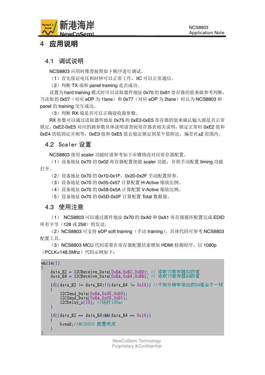
(3)NCS8803 MCU 代码需要在寄存器配置结束增加 HDMI 检测程序,以 1080p
(PCLK=148.5Mhz)代码示例如下:
NewCoSemi Technology
Proprietary &Confidential
�


 2023年江西萍乡中考道德与法治真题及答案.doc
 2012年重庆南川中考生物真题及答案.doc
 2013年江西师范大学地理学综合及文艺理论基础考研真题.doc
 2020年四川甘孜小升初语文真题及答案I卷.doc
 2020年注册岩土工程师专业基础考试真题及答案.doc
 2023-2024学年福建省厦门市九年级上学期数学月考试题及答案.doc
 2021-2022学年辽宁省沈阳市大东区九年级上学期语文期末试题及答案.doc
 2022-2023学年北京东城区初三第一学期物理期末试卷及答案.doc
 2018上半年江西教师资格初中地理学科知识与教学能力真题及答案.doc
 2012年河北国家公务员申论考试真题及答案-省级.doc
 2020-2021学年江苏省扬州市江都区邵樊片九年级上学期数学第一次质量检测试题及答案.doc
 2022下半年黑龙江教师资格证中学综合素质真题及答案.doc