logo资料库

SEW-IPOS手册.pdf

第1页 / 共384页
第2页 / 共384页
第3页 / 共384页
第4页 / 共384页
第5页 / 共384页
第6页 / 共384页
第7页 / 共384页
第8页 / 共384页
资料共384页,剩余部分请下载后查看
1 General Information
1.1 Structure of the safety notes
1.2 Liability for defects
1.3 Exclusion of liability
1.4 Copyright
2 Safety Notes
2.1 General information
2.2 Designated use
2.3 Target group
2.4 Programming errors
3 System Description
3.1 Introduction
3.1.1 Scope of this documentation
3.1.2 Creating programs
3.2 IPOSplus® – features
3.3 Controlling IPOSplus® units
3.3.1 Active control signal source
3.4 Technology options / application modules
3.4.1 Technology options
3.4.2 Application modules
3.5 Technical data
3.5.1 MOVIDRIVE® B
3.5.2 MOVITRAC® B
3.5.3 MQx
3.6 Reference documents
3.6.1 General manuals
3.6.2 Manuals for serial interfaces/fieldbuses
3.6.3 Manuals for synchronized axis movements
3.6.4 Manuals for application modules
3.6.5 Manuals for the MQx fieldbus interfaces
4 IPOS Variables
4.1 Introduction
4.2 Overview of the system variables
5 Task Management and Interrupts
5.1 Introduction
5.2 Task management for MOVIDRIVE® A and B
5.3 Tasks for MOVIDRIVE® A
5.4 Tasks for MOVIDRIVE® B
5.4.1 Processing time for task 1 / task 2
5.4.2 Task 3
5.4.3 Implementation information
5.4.4 Example
5.5 Interrupts
5.5.1 Example
5.6 Interrupts for MOVIDRIVE® A and B
5.6.1 Interrupt activation
5.6.2 Error interrupt
Sample
5.6.3 Touch probe DI02 interrupt
Sample
5.6.4 Timer0 interrupt
Sample
5.7 Variable interrupts with MOVIDRIVE® B
5.7.1 Calling up the variable interrupt
5.7.2 IPOS access to the internal interrupt control
Sample
Example solved in the Compiler
Example solved in the Assembler
6 Position Detection and Positioning
6.1 Encoder evaluation
6.2 Motor encoder (X15)
6.3 Encoder combinations
6.4 External encoder (X14)
6.4.1 Positioning on external encoder (X14)
6.4.2 Slip compensation with external encoder
6.5 SSI absolute encoder (DIP)
6.5.1 Startup
6.5.2 1. Select encoder type P950
6.5.3 2. Set direction of rotation of the motor P35_
6.5.4 3. Set counting direction P951 for the SSI absolute encoder
6.5.5 4. Set encoder scaling P955
6.5.6 5. Set position offset P953
6.5.7 6. Set Zero offset P954
6.5.8 7. Set encoder factors P942 and P943
6.5.9 8. Set P941 actual position source
6.6 Referencing
6.6.1 Type 0: Reference travel to zero pulse
6.6.2 Type 1: CCW end of the reference cam
6.6.3 Type 2: CW end of the reference cam
6.6.4 Type 3: CW limit switch
6.6.5 Type 4: CCW limit switch
6.6.6 Type 5: No reference travel
6.6.7 Type 6: Reference cam flush with CW limit switch
6.6.8 Type 7: Reference cam flush with CCW limit switch
6.6.9 Type 8: Without enable
6.7 Modulo function
6.7.1 Introduction
6.7.2 Operating principle
6.7.3 Travel strategies
Referencing
Positioning
"Short distance"
"CW"
"CCW"
Parameters and variables
6.7.4 Project planning
6.7.5 Project planning examples
Chain conveyor
Chain conveyor with carrier
6.7.6 Frequently asked questions
6.8 Cam controllers
6.8.1 Standard cam controller
Characteristics of the standard cam controller
Startup of the cam controller
Data structure of the standard cam controller
Example
Required parameter settings
Example solved in the Compiler
Example solved in the Assembler
6.8.2 Expanded cam controller
Characteristics of the expanded cam controller
Starting the expanded cam control
Data structure of the expanded cam control
SEW standard structure GSCAM_EXT
Structure CAM_EXT_OUT
Function chart of the expanded cam control
Example
Required parameter settings
Example solved in the Compiler
Example solved in the Assembler
7 Position Detection via Binary Inputs
7.1 Types of built-in encoders
7.2 Principle of the position detection
7.3 Position detection with MOVIDRIVE® B
7.4 Position detection with MOVITRAC® B
7.5 Position detection with MQx
7.5.1 Proximity sensor evaluation
7.5.2 DI0 and DI1 terminal assignments
7.5.3 Position detection with built-in encoder
7.5.4 Encoder monitoring
7.5.5 Storing the actual position
7.5.6 Counter
7.5.7 Connecting the built-in encoders
Connecting the NV26 proximity sensor
Connecting the EI76, ES16 incremental encoder
8 IPOSplus® and Fieldbus
8.1 Introduction
8.2 Binary inputs and outputs
8.2.1 Fieldbus interface, DIO and DIP
8.3 Cyclical process data
8.3.1 Cyclical preset process data
8.3.2 Cyclical user-specific process data
Example
Compiler
Assembler
8.4 Acyclical communication
8.5 Special features of communication via SBus
8.6 Special features of communication via RS-485
8.7 Fieldbus control words and fieldbus status words
9 IPOSplus® and Synchronized Motion
9.1 Introduction
9.2 Speed synchronization via master/slave function
9.3 Synchronous operation with a DRS option card
9.3.1 Activating and deactivating the free running function
Requirement
Command sequence in Assembler
Command sequence in the Compiler
9.3.2 Setting the zero pointfor DRS11B
Command sequence in Assembler
Command sequence in the Compiler
Control example
Sample program with IPOSplus® Compiler
9.3.3 Activating and deactivating the offset function
Requirement
Command sequence in Assembler
Command sequence in the Compiler
9.3.4 Switching between positioning and synchronous operation
9.4 Synchronous operation with technology option "Internal synchronous operation"
9.4.1 Requirements
9.5 Synchronous operation with technology option "Cam"
9.5.1 Requirements
10 IPOSplus® for MOVITRAC® B – Characteristics
10.1 Requirements
10.2 Functionality
11 IPOSplus® for MQx – Characteristics
11.1 Introduction
11.2 Starting the programming tool
11.3 Sequence control system
11.4 Digital inputs and outputs
11.5 Values of the DIAG11 variable for the error IPOS ILLOP
12 P9xx IPOS Parameters
12.1 P90x IPOS reference travel
12.1.1 P900 Reference offset
12.1.2 P901 Reference speed 1
12.1.3 P902 Reference speed 2
12.1.4 P903 Reference travel type
12.1.5 P904 Reference travel to zero pulse
12.1.6 P905 Hiperface offset X15
12.1.7 P906 Cam distance
12.2 P91x IPOSplus® parameters
12.2.1 P910 Gain X controller
12.2.2 P911/912 Positioning ramp 1/2
12.2.3 P913/P914 Travel speed CW/CCW
12.2.4 P915 Velocity precontrol
12.2.5 P916 Ramp type
12.2.6 P917 Ramp mode
12.2.7 P918 Bus setpoint source
12.3 P92x IPOS monitoring
12.3.1 P920/P921 SW limit switch CW/CCW
12.3.2 P922 Position window
12.3.3 P923 Lag error window
12.3.4 P924 Positioning interruption detection
12.4 P93x IPOSplus® special functions
12.4.1 P930 Override
12.4.2 P931 IPOS CTRL.W Task 1
12.4.3 P932 IPOS CTRL.W Task 2
12.4.4 P933 Jerk time
12.4.5 P938 Speed task 1
12.4.6 P939 Speed task 2
12.5 P94x IPOSplus® encoder
12.5.1 P940 IPOS variable edit
12.5.2 P941 Actual position source
12.5.3 P942/P943 Encoder factor numerator/denominator
12.5.4 P944 Encoder scaling ext. encoder
12.5.5 P945 Synchronous encoder type (X14)
12.5.6 P945 Synchronous encoder counting direction (X14)
12.5.7 P947 Hiperface offset X14
12.5.8 P948 Automatic encoder replacement detection
12.6 P95x absolute encoder (SSI)
12.6.1 P950 Encoder type
12.6.2 P951 Counting direction
12.6.3 P952 Cycle frequency
12.6.4 P953 Position offset
12.6.5 P954 Zero offset
12.6.6 P955 Encoder scaling
12.6.7 P956 CAN encoder baud rate
12.7 P96x IPOSplus® modulo function
12.7.1 P960 Modulo function
12.7.2 P961 Modulo numerator
12.7.3 P962 Modulo denominator
12.7.4 P963 Modulo encoder resolution
12.8 P97x IPOS synchronization
12.8.1 P970 DPRAM synchronization
12.8.2 P971 Synchronization phase
13 Compiler – Editor
13.1 Technical features
13.2 First steps
13.2.1 Step 1: Starting IPOSplus® Compiler with MOVITOOLS® MotionStudio
Requirements
MOVITOOLS® MotionStudio and creating a project
Establishing communication and scanning the network
Starting IPOSplus® Compiler
13.2.2 Step 2: Creating a new project
13.2.3 Step 3: The first IPOSplus® program
Editing the IPOSplus® program
13.2.4 Step 4: Compiling and starting the IPOSplus® program
Compiling the program
Error messages during compilation
Loading the program into the unit
Starting and stopping the program
13.3 Settings for the IPOSplus® Compiler
13.4 Search function
13.5 Creating a new project
13.5.1 Project properties
13.5.2 Defining the program structure
13.6 Saving a project
13.7 Setting up a project management structure
13.8 Opening a project
13.9 Handling projects with MOVIDRIVE® B
13.9.1 Saving a project in the inverter
13.9.2 Loading a project from the inverter
13.9.3 Calling up a project from the inverter
13.10 Compiling a project
13.11 Compiling and downloading
13.12 Starting a program
13.13 Stopping a program
13.14 Comparison with unit
13.15 Debugger
13.16 Variable window
13.17 Program information
13.18 Entering instructions
13.19 Comments
13.20 Overview of the icons
14 Compiler – Programming
14.1 Preprocessor
14.2 Preprocessor statements
14.3 #include
14.4 Include folders
14.5 #define
14.6 #undef
14.7 #declare
14.8 SEW standard structures
14.9 User-defined structures
14.10 long
14.11 initial long
14.12 #pragma
14.13 Explanation of const.h and io.h / constb.h and iob.h
14.14 Identifiers
14.15 Constants
14.16 IPOSplus® variables in the Compiler
14.16.1 Example
14.17 Declaration of global variables
14.18 Indirect addressing – pointer
14.19 numof()
15 Compiler – Operators
15.1 Order of priority of operators
15.2 Unary operators
15.3 Binary operators
15.3.1 Example
15.4 Ternary operators
15.4.1 Example
16 Compiler – Constructions
16.1 if...else
16.1.1 Syntax
Example
Example
16.2 for
16.2.1 Syntax
Example
Example of a statement block
Example
Example
16.3 while
16.3.1 Syntax
Example
Example
Example
16.4 do...while
16.4.1 Syntax
Example
16.5 switch...case...default
16.5.1 Syntax
16.6 return
17 Compiler – Functions
17.1 User-defined functions
17.2 Overview of commands for standard functions
17.2.1 Standard bit functions
17.2.2 Standard communication functions
17.2.3 Standard positioning functions
17.2.4 Standard program functions
17.2.5 Standard setting functions
17.2.6 Special standard unit functions
17.3 Standard functions
17.3.1 _AxisStop
Syntax
Description
Argument
Example
17.3.2 _BitClear
Syntax
Description
Key points
Example
17.3.3 _BitMove
Syntax
Description
Key points
Example
17.3.4 _BitMoveNeg
Syntax
Description
Key points
Example
17.3.5 _BitSet
Syntax
Description
Key points
Example
17.3.6 _Copy
Syntax
Description
Key points
Example
17.3.7 _FaultReaction
Syntax
Description
Key points
Example
17.3.8 _GetSys
Syntax
Description
Key points
Example
17.3.9 _Go0
Syntax
Description
Key points
Example
17.3.10 _GoAbs
Syntax
Description
Key points
Parameter settings for all positioning commands
Example
17.3.11 _GoRel
Syntax
Description
Key points
Example
17.3.12 _InputCall
Syntax
Description
Key points
Example
17.3.13 _Memorize
Syntax
Description
Key points
Example
17.3.14 _MoviLink
Syntax
Description
Key points
Example 1
Other examples
Parameter settings for the sender (master)
Parameter settings for the receiver
17.3.15 _MovCommDef
Syntax
Description
Argument
Example
17.3.16 _MovCommOn
Syntax
Description
Key points
Example
17.3.17 _Nop
Syntax
Description
Argument
Example
17.3.18 _SBusCommDef
Syntax
Description
Key points
SCD_REC
SCD_TRCYCL
SCD_TRACYCL
Example
17.3.19 _SBusCommOn
Syntax
Description
Argument
Example
17.3.20 _SBusCommState
Syntax
Description
Key points
Example
17.3.21 _SetInterrupt
Syntax
Description
Key points
Example
17.3.22 _SetSys
Syntax
Description
Key points
Example
17.3.23 _SetTask
Syntax
Description
Argument
Example
17.3.24 _SetTask2
Syntax
Description
Key points
Example
17.3.25 _SetVarInterrupt
Syntax
Description
Key points
Example
17.3.26 _SystemCall
Syntax
Description
Key points
Example
17.3.27 _TouchProbe
Syntax
Description
Key points
Example
17.3.28 _Wait
Syntax
Description
Key points
Example
17.3.29 _WaitInput
Syntax
Description
Key points
Example
17.3.30 _WaitSystem
Syntax
Description
Key points
Example
17.3.31 _WdOff
Syntax
Description
Argument
Example
17.3.32 _WdOn
Syntax
Description
Key points
Example
18 Compiler – Examples
18.1 Setting bits and output terminals
18.2 Clearing bits and output terminals
18.3 Querying bits and input terminals
18.3.1 Testing single bits
18.3.2 Testing several bits
18.4 Querying an edge
18.4.1 Example 1
18.4.2 Example 2
18.5 Value of a number
18.6 MoviLink command
18.6.1 Reading an internal unit parameter
18.6.2 Writing a variable via SBus
18.6.3 Reading a parameter via SBus
18.7 SCOM communication
18.7.1 Receiver
18.7.2 Sender
18.8 Touch probe interrupt processing
18.9 State machine, fieldbus control with emergency mode
18.9.1 Mode 0
18.9.2 Mode 1
18.9.3 Mode 2
18.9.4 Mode 3
18.10 Compiler programming frame
19 Compiler – Error Messages
20 Assembler – Introduction
20.1 Setting the user travel units
20.1.1 Travel distance factors NUMERATOR/DENOMINATOR
Travel distance factor NUMERATOR
Travel distance factor DENOMINATOR
Example
Example
Example A: mm
Example B: Increments
Example C: Output revolutions
Practical information
20.1.2 UNIT
20.2 First steps
20.2.1 Starting the IPOSplus® Assembler
20.2.2 Creating a new program
20.2.3 Compiling and starting the program
21 Assembler – Editor
21.1 Example
21.2 Creating programs
21.2.1 Inserting command lines
21.3 Compiling and downloading
21.4 Starting/stopping programs
21.4.1 Variable window
21.5 File/unit comparison
21.6 Debugger
21.6.1 Execute to cursor
21.6.2 Single step
21.7 Loading the program from the inverter
21.8 Overview of the icons
22 Assembler – Programming
22.1 Basics
22.1.1 Program header
22.1.2 Task 1 / Task 2 / Task 3
22.1.3 Comments
22.1.4 Program branches
22.1.5 Subroutine system
22.1.6 Program loops
22.1.7 Positioning commands
22.1.8 Binary/analog inputs/outputs
22.1.9 Access to system values/parameters
22.1.10 Variables
22.1.11 Program line
22.2 Binary inputs/outputs
22.2.1 Binary inputs
Direct query
Example
Query via system variable
22.2.2 Binary outputs
Reading binary outputs
Setting the binary outputs
Setting individual outputs
Setting several outputs
Example
22.3 Analog inputs/outputs
22.3.1 Reading analog inputs/outputs
Example
22.3.2 Setting analog outputs
23 Assembler – Commands
23.1 General information
23.2 Overview of commands
23.2.1 Arithmetic commands
23.2.2 Bit commands
23.2.3 Communication commands
23.2.4 Positioning commands
23.2.5 Program commands
23.2.6 Set commands
23.2.7 Special unit commands
23.2.8 Comparison commands
23.3 Arithmetic commands
23.3.1 Fundamental operations ADD / SUB / MUL / DIV
ADD
SUB/SUBTRACT
MUL/MULTIPLY
DIV/DIVISION
23.3.2 Auxiliary arithmetic functions NOT/MOD
NOT
MOD/MODULO
23.3.3 Logical operations AND/OR/XOR
AND
OR
XOR
23.3.4 SHIFT commands SHL/SHR/ASHR
SHL/SHIFT LEFT
SHR/SHIFT RIGHT
ASHR/ARITHMETIC SHIFT RIGHT
23.4 Bit commands
23.4.1 Bit commands BSET/BCLR/BMOV/BMOVN
BSET/BIT SET
BCLR/BIT CLEAR
BMOV/BIT MOVE
BMOVN/BIT MOVE NEGATE
23.5 Communication commands
23.5.1 MOVLNK
Command structure
Structure
Parameter settings for the sender (master)
Parameter settings for the receiver
Example 1
Example 2
Example 3
23.5.2 MOVCOM
Variable structure of the process data
Variable structure of the parameter data
Sample program
23.5.3 MOVON
23.5.4 SCOM
Structure
Example
Sender and receiver settings
TRANSMIT CYCLIC:
Object structure
TRANSMIT ACYCLIC
Object structure
RECEIVE
Object structure
Example 1
23.5.5 SCOMON
Structure
23.5.6 SCOMST
Structure
23.6 Positioning commands
23.6.1 Reference travel GO0
GO0
Structure
23.6.2 GOA absolute positioning / GOR relative positioning
Parameter settings for all positioning commands
GOA/GO ABSOLUTE
Structure
GOR/GO RELATIVE
Structure
Example 1
Example 2
23.7 Program commands
23.7.1 Program command END
END
23.7.2 Subroutine call CALL
CALL
Structure
Example
23.7.3 Jump commands JMP
JMP/terminals
Structure
Example
JMP/comparison
Structure
JMP/System
Structure
23.7.4 Loop commands LOOP
LOOPB/LOOP BEGIN
Structure
LOOPE/LOOP END
Structure
Example
23.7.5 No Operation NOP / remark REM / return RET / TASK / TASK2 / wait WAIT
NOP/NO OPERATION
Structure
REM/REMARK
Structure
RET/RETURN
Structure
TASK
Structure
Example
TASK2
Structure
Example
WAIT
Structure
Example
23.8 Set commands
23.8.1 Copy variables COPY
COPY
Structure
Example
23.8.2 Read system values GETSYS
GETSYS/GET SYSTEM VALUE
Structure
23.8.3 Set commands variable SET / fault response SETFR / Indirect addressing SETI / Interrupt SETINT / system values SETSYS
SET
Structure
SETFR/SET FAULT REACTION
Structure
SETI/SET INDIRECT H = [H]
Structure
Example
SETI/SET INDIRECT [H] = H
Structure
Example
SETINT/SET INTERRUPT
Structure
Example 1
Example 2
23.8.4 SETSYS
Structure
23.8.5 VARINT
Syntax
Description
Key points
Example
23.9 Special unit commands
23.9.1 ASTOP / MEM / TOUCHP / WDOFF / WDON
ASTOP/AXIS STOP
Structure
MEM/MEMORIZE
Structure
Example
TOUCHP/TOUCH PROBE
Structure
Example 1
Example 2
WDOFF/WDON / WATCH DOG OFF/ON
Structure
Example
23.10 Comparison commands
23.10.1 Comparison operations CPEQ / CPGE / CPGT / CPLE / CPLT / CPNE
CPEQ/COMPARE EQUAL
Structure
Example 1
Example 2
CPGE/COMPARE GREATER OR EQUAL
Structure
Example 1
Example 2
CPGT/COMPARE GREATER THAN
Structure
Example 1
Example 2
CPLE/COMPARE LESS OR EQUAL
Structure
Example 1
Example 2
CPLT/COMPARE LESS THAN
Structure
Example 1
Example 2
CPNE/COMPARE NOT EQUAL
Structure
Example 1
Example 2
23.10.2 Logical operations ANDL / ORL / NOTL
ANDL LOGICAL AND
Structure
Example 1
Example 2
ORL/LOGICAL OR
Structure
Example 1
Example 2
NOTL/LOGICAL NOT
Structure
Example 1
Example 2
24 Assembler – Examples
24.1 "Flashing light" sample program
24.1.1 Sample "Controller"
Quick-start (example)
24.1.2 Sample "Positioning"
Quick-start (example)
24.2 "Hoist" sample program
24.2.1 Characteristics
24.2.2 Settings
24.2.3 Schematic structure
24.2.4 Terminal wiring
24.2.5 Setting parameters relevant to the example
24.2.6 Calculating the IPOSplus® parameters
SW limit switch
Travel distance factor numerator
Travel distance factor denominator
Unit
Travel speed
Position window
24.2.7 Input terminals
24.2.8 Output terminals
24.2.9 Program source code (with remarks)
24.3 "Jog mode" sample program
24.3.1 Characteristics
24.3.2 Settings
24.3.3 Input terminals
24.3.4 Output terminals
24.3.5 Program source code (with remarks)
24.4 "Table positioning" sample program
24.4.1 Characteristics
24.4.2 Settings
24.4.3 Input terminals
24.4.4 Output terminals
24.4.5 Program source code (with remarks)
Drive Technology \ Drive Automation \ System Integration \ Services Manual IPOSplus® Positioning and Sequence Control System Edition 11/2009 11645415 / EN
SEW-EURODRIVE—Driving the world
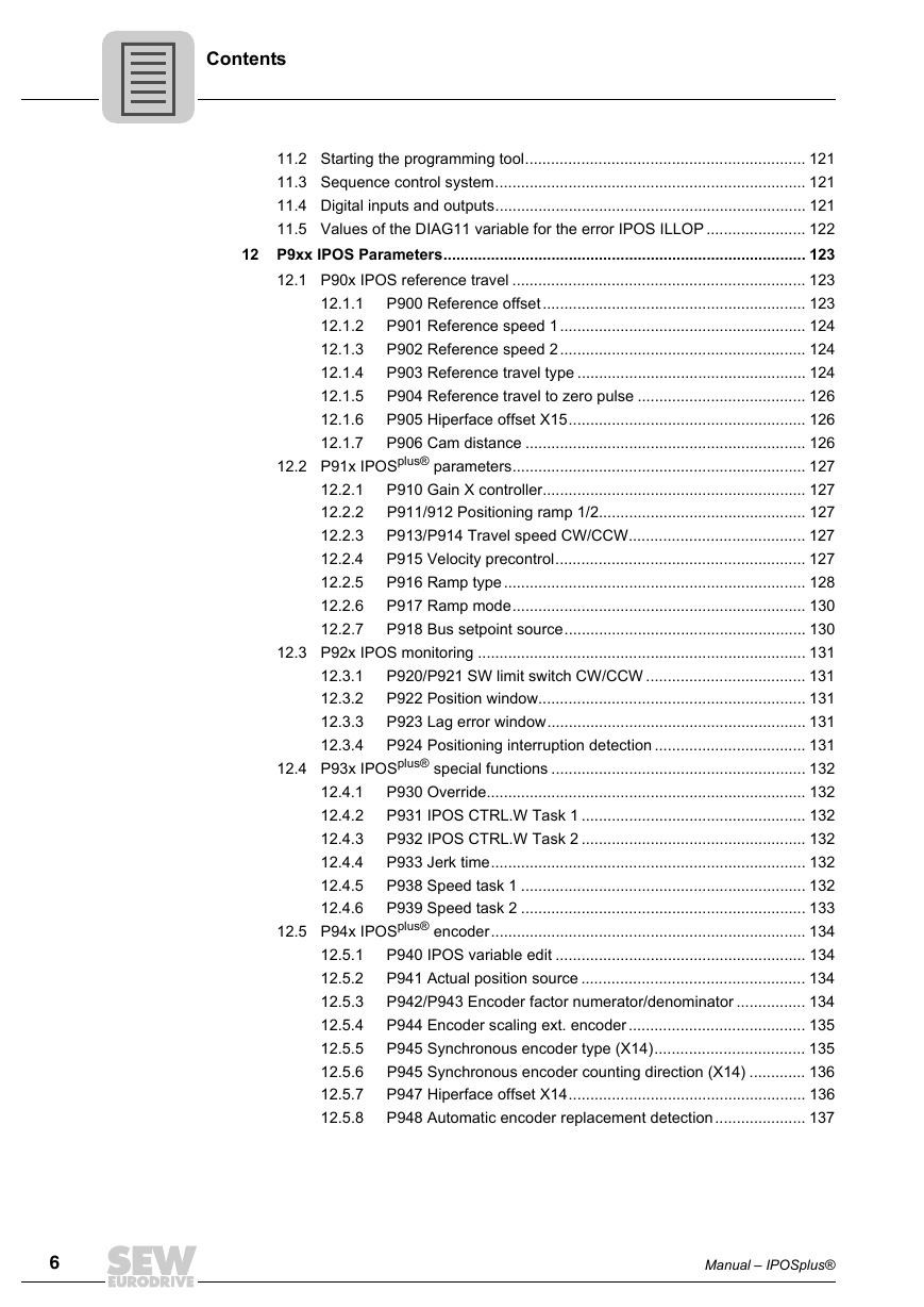
Contents 3.4 3.5 2 3 4 5 Contents 1 3.2 3.3 General Information .......................................................................................... 14 Structure of the safety notes ..................................................................... 14 1.1 Liability for defects .................................................................................... 15 1.2 1.3 Exclusion of liability................................................................................... 15 1.4 Copyright................................................................................................... 15 Safety Notes ...................................................................................................... 16 2.1 General information .................................................................................. 16 2.2 Designated use ......................................................................................... 17 Target group ............................................................................................. 17 2.3 2.4 Programming errors .................................................................................. 17 System Description........................................................................................... 18 Introduction ............................................................................................... 18 3.1 Scope of this documentation ..................................................... 18 3.1.1 3.1.2 Creating programs..................................................................... 19 IPOSplus® – features ................................................................................. 19 Controlling IPOSplus® units ....................................................................... 22 3.3.1 Active control signal source....................................................... 22 Technology options / application modules ................................................ 22 Technology options.................................................................... 22 3.4.1 3.4.2 Application modules................................................................... 23 Technical data........................................................................................... 25 MOVIDRIVE® B ......................................................................... 25 3.5.1 MOVITRAC® B .......................................................................... 25 3.5.2 3.5.3 MQx ........................................................................................... 26 Reference documents............................................................................... 27 General manuals ....................................................................... 27 3.6.1 3.6.2 Manuals for serial interfaces/fieldbuses .................................... 27 Manuals for synchronized axis movements............................... 27 3.6.3 Manuals for application modules ............................................... 27 3.6.4 3.6.5 Manuals for the MQx fieldbus interfaces ................................... 27 IPOS Variables................................................................................................... 28 4.1 Introduction ............................................................................................... 28 4.2 Overview of the system variables ............................................................. 29 Task Management and Interrupts.................................................................... 40 Introduction ............................................................................................... 40 5.1 Task management for MOVIDRIVE® A and B.......................................... 40 5.2 Tasks for MOVIDRIVE® A......................................................................... 43 5.3 Tasks for MOVIDRIVE® B......................................................................... 43 5.4 Processing time for task 1 / task 2............................................. 43 5.4.1 5.4.2 Task 3........................................................................................ 44 Implementation information ....................................................... 44 5.4.3 5.4.4 Example..................................................................................... 45 3.6 Manual – IPOSplus® 3
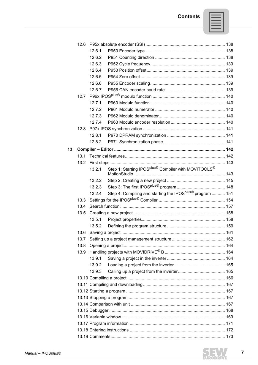
Contents 6 5.5 5.6 5.7 Interrupts................................................................................................... 45 5.5.1 Example..................................................................................... 46 Interrupts for MOVIDRIVE® A and B......................................................... 46 Interrupt activation ..................................................................... 46 5.6.1 Error interrupt............................................................................. 46 5.6.2 5.6.3 Touch probe DI02 interrupt........................................................ 47 5.6.4 Timer0 interrupt ......................................................................... 48 Variable interrupts with MOVIDRIVE® B................................................... 49 5.7.1 Calling up the variable interrupt................................................. 49 IPOS access to the internal interrupt control ............................. 50 5.7.2 Position Detection and Positioning................................................................. 53 6.1 Encoder evaluation ................................................................................... 53 6.2 Motor encoder (X15) ................................................................................. 54 Encoder combinations .............................................................................. 54 6.3 External encoder (X14) ............................................................................. 57 6.4 6.4.1 Positioning on external encoder (X14)....................................... 57 6.4.2 Slip compensation with external encoder .................................. 57 SSI absolute encoder (DIP) ...................................................................... 60 6.5.1 Startup ....................................................................................... 60 1. Select encoder type P950...................................................... 60 6.5.2 2. Set direction of rotation of the motor P35_ ............................ 61 6.5.3 3. Set counting direction P951 for the SSI absolute encoder .... 61 6.5.4 6.5.5 4. Set encoder scaling P955...................................................... 61 5. Set position offset P953......................................................... 61 6.5.6 6. Set Zero offset P954.............................................................. 62 6.5.7 6.5.8 7. Set encoder factors P942 and P943...................................... 62 6.5.9 8. Set P941 actual position source ............................................ 62 Referencing............................................................................................... 63 6.6.1 Type 0: Reference travel to zero pulse...................................... 67 Type 1: CCW end of the reference cam .................................... 67 6.6.2 Type 2: CW end of the reference cam....................................... 68 6.6.3 Type 3: CW limit switch ............................................................. 69 6.6.4 6.6.5 Type 4: CCW limit switch........................................................... 69 Type 5: No reference travel ....................................................... 70 6.6.6 Type 6: Reference cam flush with CW limit switch.................... 70 6.6.7 6.6.8 Type 7: Reference cam flush with CCW limit switch ................. 71 Type 8: Without enable.............................................................. 72 6.6.9 6.7 Modulo function......................................................................................... 73 Introduction................................................................................ 73 Operating principle .................................................................... 74 Travel strategies ........................................................................ 77 Project planning......................................................................... 80 Project planning examples......................................................... 80 Frequently asked questions....................................................... 83 6.7.1 6.7.2 6.7.3 6.7.4 6.7.5 6.7.6 6.5 6.6 4 Manual – IPOSplus®
Contents 6.8 Cam controllers......................................................................................... 84 Standard cam controller............................................................. 85 6.8.1 6.8.2 Expanded cam controller........................................................... 89 Position Detection via Binary Inputs............................................................... 96 Types of built-in encoders......................................................................... 96 7.1 7.2 Principle of the position detection ............................................................. 96 Position detection with MOVIDRIVE® B.................................................... 97 7.3 Position detection with MOVITRAC® B..................................................... 98 7.4 7.5 Position detection with MQx...................................................................... 99 Proximity sensor evaluation....................................................... 99 7.5.1 DI0 and DI1 terminal assignments............................................. 99 7.5.2 Position detection with built-in encoder ................................... 100 7.5.3 7.5.4 Encoder monitoring.................................................................. 100 Storing the actual position ....................................................... 100 7.5.5 Counter.................................................................................... 101 7.5.6 7.5.7 Connecting the built-in encoders ............................................. 101 IPOSplus® and Fieldbus ................................................................................... 102 Introduction ............................................................................................. 102 8.1 8.2 Binary inputs and outputs ....................................................................... 103 8.2.1 Fieldbus interface, DIO and DIP.............................................. 103 Cyclical process data .............................................................................. 103 8.3.1 Cyclical preset process data.................................................... 103 8.3.2 Cyclical user-specific process data.......................................... 104 Acyclical communication......................................................................... 105 8.4 Special features of communication via SBus.......................................... 105 8.5 Special features of communication via RS-485 ...................................... 106 8.6 8.7 Fieldbus control words and fieldbus status words .................................. 106 IPOSplus® and Synchronized Motion ............................................................. 107 9.1 Introduction ............................................................................................. 107 Speed synchronization via master/slave function ................................... 107 9.2 Synchronous operation with a DRS option card ..................................... 107 9.3 9.3.1 Activating and deactivating the free running function .............. 108 Setting the zero point for DRS11B........................................... 109 9.3.2 Activating and deactivating the offset function......................... 111 9.3.3 9.3.4 Switching between positioning and synchronous operation .... 113 Synchronous operation with technology option "Internal synchronous operation"................................................................................................ 115 9.4.1 Requirements .......................................................................... 115 Synchronous operation with technology option "Cam" ........................... 116 Requirements .......................................................................... 117 9.5.1 IPOSplus® for MOVITRAC® B – Characteristics............................................. 118 10.1 Requirements.......................................................................................... 118 10.2 Functionality............................................................................................ 119 IPOSplus® for MQx – Characteristics.............................................................. 120 11.1 Introduction ............................................................................................. 120 9.4 8.3 9.5 7 8 9 10 11 Manual – IPOSplus® 5
Contents 12.1.1 12.1.2 12.1.3 12.1.4 12.1.5 12.1.6 12.1.7 12.2.1 12.2.2 12.2.3 12.2.4 12.2.5 12.2.6 12.2.7 12.3.1 12.3.2 12.3.3 12.3.4 11.2 Starting the programming tool................................................................. 121 11.3 Sequence control system........................................................................ 121 11.4 Digital inputs and outputs........................................................................ 121 11.5 Values of the DIAG11 variable for the error IPOS ILLOP ....................... 122 12 P9xx IPOS Parameters.................................................................................... 123 12.1 P90x IPOS reference travel .................................................................... 123 P900 Reference offset............................................................. 123 P901 Reference speed 1......................................................... 124 P902 Reference speed 2......................................................... 124 P903 Reference travel type ..................................................... 124 P904 Reference travel to zero pulse ....................................... 126 P905 Hiperface offset X15....................................................... 126 P906 Cam distance ................................................................. 126 12.2 P91x IPOSplus® parameters.................................................................... 127 P910 Gain X controller............................................................. 127 P911/912 Positioning ramp 1/2................................................ 127 P913/P914 Travel speed CW/CCW......................................... 127 P915 Velocity precontrol.......................................................... 127 P916 Ramp type...................................................................... 128 P917 Ramp mode.................................................................... 130 P918 Bus setpoint source........................................................ 130 12.3 P92x IPOS monitoring ............................................................................ 131 P920/P921 SW limit switch CW/CCW ..................................... 131 P922 Position window.............................................................. 131 P923 Lag error window............................................................ 131 P924 Positioning interruption detection ................................... 131 12.4 P93x IPOSplus® special functions ........................................................... 132 P930 Override.......................................................................... 132 P931 IPOS CTRL.W Task 1 .................................................... 132 P932 IPOS CTRL.W Task 2 .................................................... 132 P933 Jerk time......................................................................... 132 P938 Speed task 1 .................................................................. 132 P939 Speed task 2 .................................................................. 133 12.5 P94x IPOSplus® encoder......................................................................... 134 P940 IPOS variable edit .......................................................... 134 P941 Actual position source .................................................... 134 P942/P943 Encoder factor numerator/denominator ................ 134 P944 Encoder scaling ext. encoder......................................... 135 P945 Synchronous encoder type (X14)................................... 135 P945 Synchronous encoder counting direction (X14) ............. 136 P947 Hiperface offset X14....................................................... 136 P948 Automatic encoder replacement detection..................... 137 12.5.1 12.5.2 12.5.3 12.5.4 12.5.5 12.5.6 12.5.7 12.5.8 12.4.1 12.4.2 12.4.3 12.4.4 12.4.5 12.4.6 6 Manual – IPOSplus®
Contents 12.6.1 12.6.2 12.6.3 12.6.4 12.6.5 12.6.6 12.6.7 12.6 P95x absolute encoder (SSI) .................................................................. 138 P950 Encoder type .................................................................. 138 P951 Counting direction .......................................................... 138 P952 Cycle frequency.............................................................. 139 P953 Position offset................................................................. 139 P954 Zero offset ...................................................................... 139 P955 Encoder scaling.............................................................. 139 P956 CAN encoder baud rate.................................................. 139 12.7 P96x IPOSplus® modulo function ............................................................ 140 P960 Modulo function.............................................................. 140 P961 Modulo numerator .......................................................... 140 P962 Modulo denominator....................................................... 140 P963 Modulo encoder resolution............................................. 140 12.8 P97x IPOS synchronization .................................................................... 141 P970 DPRAM synchronization ................................................ 141 P971 Synchronization phase................................................... 141 13 Compiler – Editor ............................................................................................ 142 13.1 Technical features................................................................................... 142 13.2 First steps ............................................................................................... 143 12.7.1 12.7.2 12.7.3 12.7.4 12.8.1 12.8.2 13.2.1 13.5.1 13.5.2 13.2.2 13.2.3 13.2.4 Step 1: Starting IPOSplus® Compiler with MOVITOOLS® MotionStudio............................................................................ 143 Step 2: Creating a new project ................................................ 145 Step 3: The first IPOSplus® program........................................ 148 Step 4: Compiling and starting the IPOSplus® program ........... 151 13.3 Settings for the IPOSplus® Compiler ....................................................... 154 13.4 Search function ....................................................................................... 157 13.5 Creating a new project ............................................................................ 158 Project properties..................................................................... 158 Defining the program structure ................................................ 159 13.6 Saving a project ...................................................................................... 161 13.7 Setting up a project management structure ............................................ 162 13.8 Opening a project.................................................................................... 164 13.9 Handling projects with MOVIDRIVE® B .................................................. 164 Saving a project in the inverter ................................................ 164 Loading a project from the inverter.......................................... 165 Calling up a project from the inverter....................................... 165 13.10 Compiling a project ................................................................................. 166 13.11 Compiling and downloading.................................................................... 167 13.12 Starting a program .................................................................................. 167 13.13 Stopping a program ................................................................................ 167 13.14 Comparison with unit .............................................................................. 167 13.15 Debugger ................................................................................................ 168 13.16 Variable window...................................................................................... 169 13.17 Program information ............................................................................... 171 13.18 Entering instructions ............................................................................... 172 13.19 Comments............................................................................................... 173 13.9.1 13.9.2 13.9.3 Manual – IPOSplus® 7
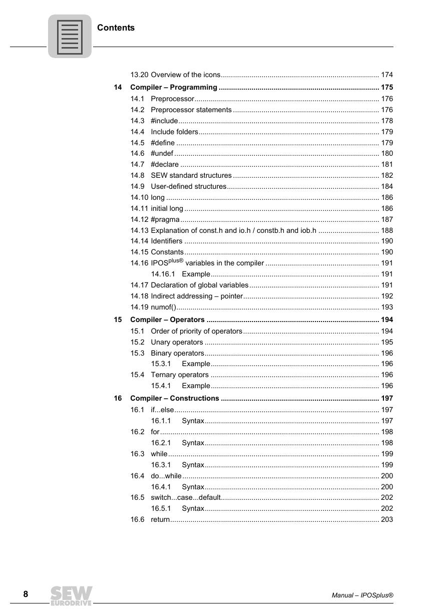
Contents 13.20 Overview of the icons.............................................................................. 174 14 Compiler – Programming ............................................................................... 175 14.1 Preprocessor........................................................................................... 176 14.2 Preprocessor statements ........................................................................ 176 14.3 #include................................................................................................... 178 14.4 Include folders......................................................................................... 179 14.5 #define .................................................................................................... 179 14.6 #undef ..................................................................................................... 180 14.7 #declare .................................................................................................. 181 14.8 SEW standard structures ........................................................................ 182 14.9 User-defined structures........................................................................... 184 14.10 long ......................................................................................................... 186 14.11 initial long ................................................................................................ 186 14.12 #pragma.................................................................................................. 187 14.13 Explanation of const.h and io.h / constb.h and iob.h .............................. 188 14.14 Identifiers ................................................................................................ 190 14.15 Constants................................................................................................ 190 14.16 IPOSplus® variables in the compiler ........................................................ 191 14.16.1 Example................................................................................... 191 14.17 Declaration of global variables................................................................ 191 14.18 Indirect addressing – pointer................................................................... 192 14.19 numof().................................................................................................... 193 15 Compiler – Operators ..................................................................................... 194 15.1 Order of priority of operators................................................................... 194 15.2 Unary operators ...................................................................................... 195 15.3 Binary operators...................................................................................... 196 Example................................................................................... 196 15.4 Ternary operators ................................................................................... 196 Example................................................................................... 196 16 Compiler – Constructions .............................................................................. 197 16.1 if...else..................................................................................................... 197 Syntax...................................................................................... 197 16.2 for............................................................................................................ 198 Syntax...................................................................................... 198 16.3 while........................................................................................................ 199 Syntax...................................................................................... 199 16.4 do...while................................................................................................. 200 Syntax...................................................................................... 200 16.5 switch...case...default.............................................................................. 202 Syntax...................................................................................... 202 16.6 return....................................................................................................... 203 15.3.1 15.4.1 16.2.1 16.3.1 16.1.1 16.4.1 16.5.1 8 Manual – IPOSplus®
分享到:
收藏