logo资料库

常用自动测试用visa命令.pdf

第1页 / 共206页
第2页 / 共206页
第3页 / 共206页
第4页 / 共206页
第5页 / 共206页
第6页 / 共206页
第7页 / 共206页
第8页 / 共206页
资料共206页,剩余部分请下载后查看
Safety Precautions
Conventions Used in This Manual
How To Use This Manual
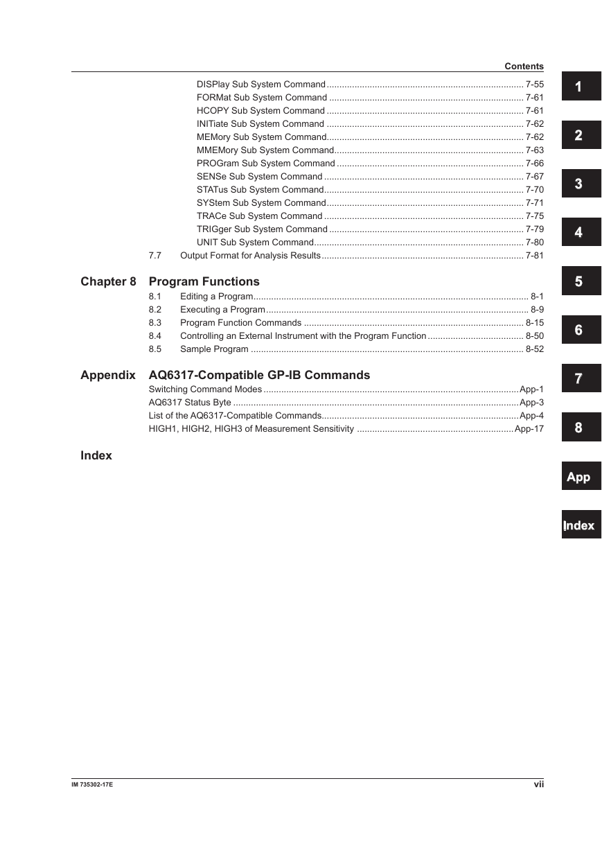
Contents
Chapter 1 Remote Control Function
1.1 Remote Interfaces
1.2 Switching between Local and Remote
1.3 Sending/Receiving Remote Commands
Chapter 2 GP-IB Interface (GP-IB1 Port)
2.1 Connecting via GP-IB
2.2 GP-IB Interface Function
2.3 GP-IB Interface Specifications
2.4 Setting the GP-IB Address
2.5 Responses to Interface Messages
2.6 Sample Program
Chapter 3 Ethernet
3.1 Connecting via Ethernet
3.2 Setting Up Ethernet
3.3 Sample Program
Chapter 4 Serial (RS-232C) Interface
4.1 Connecting via the Serial (RS-232) Interface
4.2 Remote Control Using Commands
4.3 Setting Up RS-232
Chapter 5 GP-IB Interface (GP-IB 2 Port )
5.1 Connecting via GP-IB2
5.2 GP-IB Interface Specifications
5.3 Setting the GP-IB Address
Chapter 6 Status Registers
6.1 Status Registers
6.2 Status Byte Registers
6.3 Standard Event Status Registers
6.4 Operation Status Registers
6.5 Questionable Status Registers
Chapter 7 Remote Commands
7.1 Rules of Syntax and Command Types
7.2 Table of Correspondence between Soft Keys and Remote Commands
7.3 ANALYSIS Setting Parameters
7.4 Remote Command Tree
7.5 Common Commands
7.6 Instrument-Specific Commands
ABORt Sub System Command
CALCulate Sub System Command
CALibration Sub System Command
DISPlay Sub System Command
FORMat Sub System Command
HCOPY Sub System Command
INITiate Sub System Command
MEMory Sub System Command
MMEMory Sub System Command
PROGram Sub System Command
SENSe Sub System Command
STATus Sub System Command
SYStem Sub System Command
TRACe Sub System Command
TRIGger Sub System Command
UNIT Sub System Command
7.7 Output Format for Analysis Results
Chapter 8 Program Functions
8.1 Editing a Program
8.2 Executing a Program
8.3 Program Function Commands
8.4 Controlling an External Instrument with the Program Function
8.5 Sample Program
Appendix AQ6317-Compatible GP-IB Commands
Switching Command Modes
AQ6317 Status Byte
List of the AQ6317-Compatible Commands
HIGH1, HIGH2, HIGH3 of Measurement Sensitivity
Index
User’s Manual AQ6370B/AQ6375 Optical Spectrum Analyzer Remote Control IM 735302-17E 1st Edition
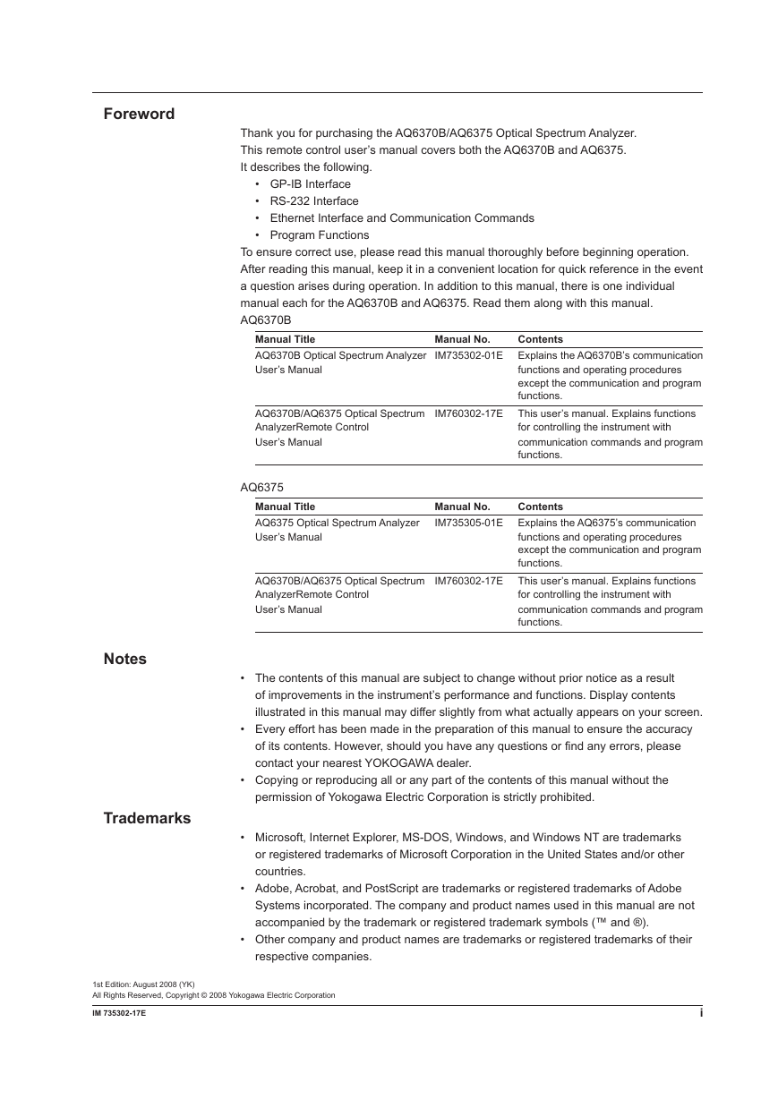
Foreword Thank you for purchasing the AQ6370B/AQ6375 Optical Spectrum Analyzer. This remote control user’s manual covers both the AQ6370B and AQ6375. It describes the following. • GP-IB Interface • RS-232 Interface • Ethernet Interface and Communication Commands • Program Functions To ensure correct use, please read this manual thoroughly before beginning operation. After reading this manual, keep it in a convenient location for quick reference in the event a question arises during operation. In addition to this manual, there is one individual manual each for the AQ6370B and AQ6375. Read them along with this manual. AQ6370B Manual Title AQ6370B Optical Spectrum Analyzer IM735302-01E Explains the AQ6370B’s communication User’s Manual Manual No. Contents functions and operating procedures except the communication and program functions. AQ6370B/AQ6375 Optical Spectrum IM760302-17E This user’s manual. Explains functions AnalyzerRemote Control User’s Manual for controlling the instrument with communication commands and program functions. AQ6375 Manual Title AQ6375 Optical Spectrum Analyzer User’s Manual Contents Manual No. IM735305-01E Explains the AQ6375’s communication functions and operating procedures except the communication and program functions. AQ6370B/AQ6375 Optical Spectrum IM760302-17E This user’s manual. Explains functions AnalyzerRemote Control User’s Manual for controlling the instrument with communication commands and program functions. Notes Trademarks • The contents of this manual are subject to change without prior notice as a result of improvements in the instrument’s performance and functions. Display contents illustrated in this manual may differ slightly from what actually appears on your screen. • Every effort has been made in the preparation of this manual to ensure the accuracy of its contents. However, should you have any questions or find any errors, please contact your nearest YOKOGAWA dealer. • Copying or reproducing all or any part of the contents of this manual without the permission of Yokogawa Electric Corporation is strictly prohibited. • Microsoft, Internet Explorer, MS-DOS, Windows, and Windows NT are trademarks or registered trademarks of Microsoft Corporation in the United States and/or other countries. • Adobe, Acrobat, and PostScript are trademarks or registered trademarks of Adobe Systems incorporated. The company and product names used in this manual are not accompanied by the trademark or registered trademark symbols (™ and ®). • Other company and product names are trademarks or registered trademarks of their respective companies. 1st Edition: August 2008 (YK) All Rights Reserved, Copyright © 2008 Yokogawa Electric Corporation IM 735302-17E i
Revisions 1st Edition August, 2008 ii IM 735302-17E
Safety Precautions This instrument is an IEC standard safety class I device (with protective grounding terminal). To ensure safe and correct operation of the instrument, you must take the safety precautions given below. The instrument’s protective functions may not work if used in a manner not described in this manual. Yokogawa bears no responsibility for, nor implies any warranty against damages occurring as a result of failure to take these precautions. The following safety symbols and wording is used in this manual. Warning: Handle with care. Refer to the user’s manual or service manual. This symbol appears on dangerous locations on the instrument which require special instructions for proper handling or use. The same symbol appears in the corresponding place in the manual to identify those instructions. Alternating current ON (power) OFF (power) IM 735302-17E iii
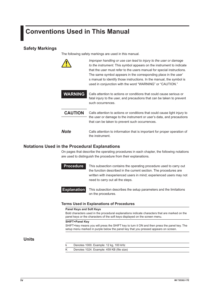
Conventions Used in This Manual Safety Markings The following safety markings are used in this manual. Improper handling or use can lead to injury to the user or damage to the instrument. This symbol appears on the instrument to indicate that the user must refer to the users manual for special instructions. The same symbol appears in the corresponding place in the user’ s manual to identify those instructions. In the manual, the symbol is used in conjunction with the word “WARNING” or “CAUTION.” WARNING Calls attention to actions or conditions that could cause serious or fatal injury to the user, and precautions that can be taken to prevent such occurrences. CAUTION Calls attention to actions or conditions that could cause light injury to the user or damage to the instrument or user’s data, and precautions that can be taken to prevent such occurrences. Note Calls attention to information that is important for proper operation of the instrument. Notations Used in the Procedural Explanations On pages that describe the operating procedures in each chapter, the following notations are used to distinguish the procedure from their explanations. Procedure This subsection contains the operating procedure used to carry out the function described in the current section. The procedures are written with inexperienced users in mind; experienced users may not need to carry out all the steps. Explanation This subsection describes the setup parameters and the limitations on the procedures. Terms Used in Explanations of Procedures Panel Keys and Soft Keys Bold characters used in the procedural explanations indicate characters that are marked on the panel keys or the characters of the soft keys displayed on the screen menu. SHIFT+Panel Key SHIFT+key means you will press the SHIFT key to turn it ON and then press the panel key. The setup menu marked in purple below the panel key that you pressed appears on screen. Denotes 1000. Example: 12 kg, 100 kHz k K Denotes 1024. Example: 459 KB (file size) IM 735302-17E Units iv
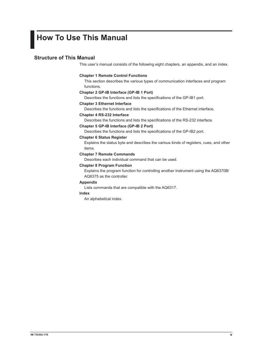
How To Use This Manual Structure of This Manual This user’s manual consists of the following eight chapters, an appendix, and an index. Chapter 1 Remote Control Functions This section describes the various types of communication interfaces and program functions. Chapter 2 GP-IB Interface (GP-IB 1 Port) Describes the functions and lists the specifications of the GP-IB1 port. Chapter 3 Ethernet Interface Describes the functions and lists the specifications of the Ethernet interface. Chapter 4 RS-232 Interface Describes the functions and lists the specifications of the RS-232 interface. Chapter 5 GP-IB Interface (GP-IB 2 Port) Describes the functions and lists the specifications of the GP-IB2 port. Chapter 6 Status Register Explains the status byte and describes the various kinds of registers, cues, and other items. Chapter 7 Remote Commands Describes each individual command that can be used. Chapter 8 Program Function Explains the program function for controlling another instrument using the AQ6370B/ AQ6375 as the controller. Appendix Lists commands that are compatible with the AQ6317. Index An alphabetical index. IM 735302-17E v
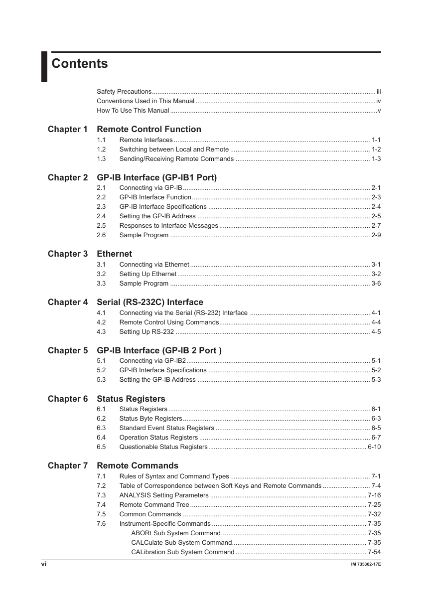
Contents Safety Precautions ........................................................................................................................... iii Conventions Used in This Manual ...................................................................................................iv How To Use This Manual ..................................................................................................................v Chapter 1 Remote Control Function 1.1 1.2 1.3 Remote Interfaces ............................................................................................................ 1-1 Switching between Local and Remote ............................................................................. 1-2 Sending/Receiving Remote Commands .......................................................................... 1-3 Chapter 2 GP-IB Interface (GP-IB1 Port) 2.1 2.2 2.3 2.4 2.5 2.6 Connecting via GP-IB ....................................................................................................... 2-1 GP-IB Interface Function .................................................................................................. 2-3 GP-IB Interface Specifications ......................................................................................... 2-4 Setting the GP-IB Address ............................................................................................... 2-5 Responses to Interface Messages ................................................................................... 2-7 Sample Program .............................................................................................................. 2-9 Chapter 3 Ethernet 3.1 3.2 3.3 Connecting via Ethernet ................................................................................................... 3-1 Setting Up Ethernet .......................................................................................................... 3-2 Sample Program .............................................................................................................. 3-6 Chapter 4 Serial (RS-232C) Interface 4.1 4.2 4.3 Connecting via the Serial (RS-232) Interface .................................................................. 4-1 Remote Control Using Commands ................................................................................... 4-4 Setting Up RS-232 ........................................................................................................... 4-5 Chapter 5 GP-IB Interface (GP-IB 2 Port ) 5.1 5.2 5.3 Connecting via GP-IB2 ..................................................................................................... 5-1 GP-IB Interface Specifications ......................................................................................... 5-2 Setting the GP-IB Address ............................................................................................... 5-3 Chapter 6 Status Registers Chapter 7 Remote Commands 6.1 6.2 6.3 6.4 6.5 7.1 7.2 7.3 7.4 7.5 7.6 Status Registers ............................................................................................................... 6-1 Status Byte Registers ....................................................................................................... 6-3 Standard Event Status Registers ..................................................................................... 6-5 Operation Status Registers .............................................................................................. 6-7 Questionable Status Registers ....................................................................................... 6-10 Rules of Syntax and Command Types ............................................................................. 7-1 Table of Correspondence between Soft Keys and Remote Commands .......................... 7-4 ANALYSIS Setting Parameters ...................................................................................... 7-16 Remote Command Tree ................................................................................................. 7-25 Common Commands ..................................................................................................... 7-32 Instrument-Specific Commands ..................................................................................... 7-35 ABORt Sub System Command ................................................................................ 7-35 CALCulate Sub System Command.......................................................................... 7-35 CALibration Sub System Command ........................................................................ 7-54 vi IM 735302-17E
1 2 3 4 5 6 7 8 App Index Contents DISPlay Sub System Command .............................................................................. 7-55 FORMat Sub System Command ............................................................................. 7-61 HCOPY Sub System Command .............................................................................. 7-61 INITiate Sub System Command .............................................................................. 7-62 MEMory Sub System Command .............................................................................. 7-62 MMEMory Sub System Command ........................................................................... 7-63 PROGram Sub System Command .......................................................................... 7-66 SENSe Sub System Command ............................................................................... 7-67 STATus Sub System Command ............................................................................... 7-70 SYStem Sub System Command .............................................................................. 7-71 TRACe Sub System Command ............................................................................... 7-75 TRIGger Sub System Command ............................................................................. 7-79 UNIT Sub System Command ................................................................................... 7-80 Output Format for Analysis Results ................................................................................ 7-81 7.7 Chapter 8 Program Functions 8.1 8.2 8.3 8.4 8.5 Editing a Program ............................................................................................................. 8-1 Executing a Program ........................................................................................................ 8-9 Program Function Commands ....................................................................................... 8-15 Controlling an External Instrument with the Program Function ...................................... 8-50 Sample Program ............................................................................................................ 8-52 Appendix AQ6317-Compatible GP-IB Commands Switching Command Modes .....................................................................................................App-1 AQ6317 Status Byte .................................................................................................................App-3 List of the AQ6317-Compatible Commands..............................................................................App-4 HIGH1, HIGH2, HIGH3 of Measurement Sensitivity ..............................................................App-17 Index IM 735302-17E vii
分享到:
收藏