Preliminary Datasheet- please see the Known Issues list
CONFIDENTIAL�
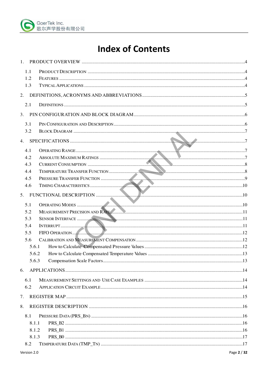
Restricted
1. Security warning
The information contained in this document is the exclusive property of GoerTek Inc. and should not be disclosed to any
third party without the written consent of GoerTek Inc.
2. Publication history
Version
Date
Description
Author
Approved
1.0
2.0
Version 2.0
2015.5.29
New design
Wiming
Sammy
2015.8.10
Update product
name
Wiming
Sammy
Page 1 / 32
CONFIDENTIAL�
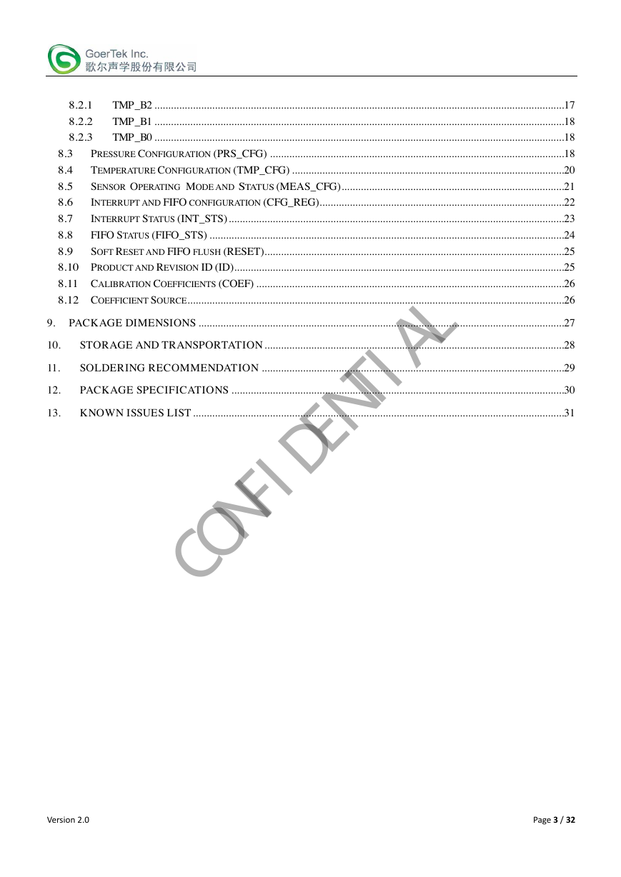
Index of Contents
1. PRODUCT OVERVIEW ..........................................................................................................................................4
1.1
1.2
1.3
PRODUCT DESCRIPTION .....................................................................................................................................4
FEATURES .............................................................................................................................................................4
TYPICAL APPLICATIONS ........................................................................................................................................4
2. DEFINITIONS, ACRONYMS AND ABBREVIATIONS .......................................................................................5
2.1 DEFINITIONS .........................................................................................................................................................5
3. PIN CONFIGURATION AND BLOCK DIAGRAM ..............................................................................................6
3.1
3.2
PIN CONFIGURATION AND DESCRIPTION ...............................................................................................................6
BLOCK DIAGRAM .................................................................................................................................................7
4. SPECIFICATIONS ....................................................................................................................................................7
4.1 OPERATING RANGE ...............................................................................................................................................7
4.2 ABSOLUTE MAXIMUM RATINGS ...........................................................................................................................7
4.3
4.4
4.5
4.6
CURRENT CONSUMPTION .....................................................................................................................................8
TEMPERATURE TRANSFER FUNCTION ...................................................................................................................8
PRESSURE TRANSFER FUNCTION ..........................................................................................................................9
TIMING CHARACTERISTICS .................................................................................................................................10
5. FUNCTIONAL DESCRIPTION ............................................................................................................................10
5.1 OPERATING MODES ............................................................................................................................................10
5.2 MEASUREMENT PRECISION AND RATE ................................................................................................................ 11
5.3
5.4
5.5
5.6
SENSOR INTERFACE ............................................................................................................................................ 11
INTERRUPT .......................................................................................................................................................... 11
FIFO OPERATION ................................................................................................................................................12
CALIBRATION AND MEASUREMENT COMPENSATION ..........................................................................................12
5.6.1
5.6.2
5.6.3
How to Calculate Compensated Pressure Values ...................................................................................12
How to Calculate Compensated Temperature Values ................................................................................13
Compensation Scale Factors ......................................................................................................................13
6. APPLICATIONS ......................................................................................................................................................14
6.1 MEASUREMENT SETTINGS AND USE CASE EXAMPLES ...................................................................................14
6.2 APPLICATION CIRCUIT EXAMPLE ........................................................................................................................14
7. REGISTER MAP .....................................................................................................................................................15
8. REGISTER DESCRIPTION ..................................................................................................................................16
8.1
PRESSURE DATA (PRS_BN) ................................................................................................................................16
8.1.1
8.1.2
8.1.3
PRS_B2 ......................................................................................................................................................16
PRS_B1 ......................................................................................................................................................16
PRS_B0 ......................................................................................................................................................17
8.2
TEMPERATURE DATA (TMP_TN) ........................................................................................................................17
Version 2.0
Page 2 / 32
CONFIDENTIAL�
8.2.1
8.2.2
8.2.3
TMP_B2 .....................................................................................................................................................17
TMP_B1 .....................................................................................................................................................18
TMP_B0 .....................................................................................................................................................18
8.3
8.4
8.5
8.6
8.7
8.8
8.9
PRESSURE CONFIGURATION (PRS_CFG) ...........................................................................................................18
TEMPERATURE CONFIGURATION (TMP_CFG) ...................................................................................................20
SENSOR OPERATING MODE AND STATUS (MEAS_CFG) .................................................................................21
INTERRUPT AND FIFO CONFIGURATION (CFG_REG).........................................................................................22
INTERRUPT STATUS (INT_STS) ..........................................................................................................................23
FIFO STATUS (FIFO_STS) .................................................................................................................................24
SOFT RESET AND FIFO FLUSH (RESET).............................................................................................................25
8.10 PRODUCT AND REVISION ID (ID) ........................................................................................................................25
8.11 CALIBRATION COEFFICIENTS (COEF) ................................................................................................................26
8.12 COEFFICIENT SOURCE .........................................................................................................................................26
9. PACKAGE DIMENSIONS .....................................................................................................................................27
10.
STORAGE AND TRANSPORTATION .............................................................................................................28
11.
SOLDERING RECOMMENDATION ..............................................................................................................29
12.
PACKAGE SPECIFICATIONS .........................................................................................................................30
13. KNOWN ISSUES LIST .......................................................................................................................................31
Version 2.0
Page 3 / 32
CONFIDENTIAL�
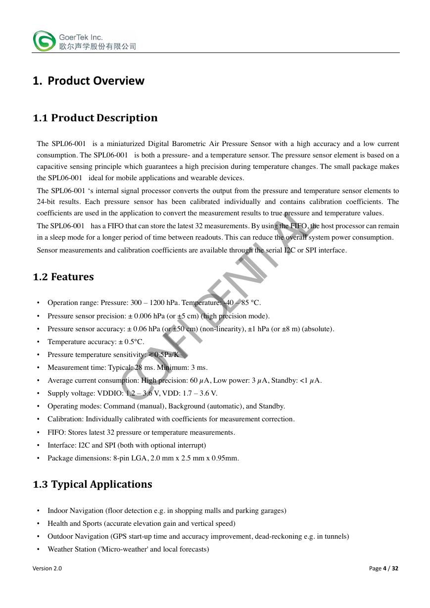
1. Product Overview
1.1 Product Description
The SPL06-001 is a miniaturized Digital Barometric Air Pressure Sensor with a high accuracy and a low current
consumption. The SPL06-001 is both a pressure- and a temperature sensor. The pressure sensor element is based on a
capacitive sensing principle which guarantees a high precision during temperature changes. The small package makes
the SPL06-001 ideal for mobile applications and wearable devices.
The SPL06-001 ‘s internal signal processor converts the output from the pressure and temperature sensor elements to
24-bit results. Each pressure sensor has been calibrated individually and contains calibration coefficients. The
coefficients are used in the application to convert the measurement results to true pressure and temperature values.
The SPL06-001 has a FIFO that can store the latest 32 measurements. By using the FIFO, the host processor can remain
in a sleep mode for a longer period of time between readouts. This can reduce the overall system power consumption.
Sensor measurements and calibration coefficients are available through the serial I2C or SPI interface.
1.2 Features
• Operation range: Pressure: 300 – 1200 hPa. Temperature: -40 – 85 °C.
• Pressure sensor precision: ± 0.006 hPa (or ±5 cm) (high precision mode).
• Pressure sensor accuracy: ± 0.06 hPa (or ±50 cm) (non-linearity), ±1 hPa (or ±8 m) (absolute).
• Temperature accuracy: ± 0.5°C.
• Pressure temperature sensitivity: < 0.5Pa/K
• Measurement time: Typical: 28 ms. Minimum: 3 ms.
• Average current consumption: High precision: 60 µA, Low power: 3 µA, Standby: <1 µA.
• Supply voltage: VDDIO: 1.2 – 3.6 V, VDD: 1.7 – 3.6 V.
• Operating modes: Command (manual), Background (automatic), and Standby.
• Calibration: Individually calibrated with coefficients for measurement correction.
• FIFO: Stores latest 32 pressure or temperature measurements.
•
Interface: I2C and SPI (both with optional interrupt)
• Package dimensions: 8-pin LGA, 2.0 mm x 2.5 mm x 0.95mm.
1.3 Typical Applications
•
Indoor Navigation (floor detection e.g. in shopping malls and parking garages)
• Health and Sports (accurate elevation gain and vertical speed)
• Outdoor Navigation (GPS start-up time and accuracy improvement, dead-reckoning e.g. in tunnels)
• Weather Station ('Micro-weather' and local forecasts)
Version 2.0
Page 4 / 32
CONFIDENTIAL�
2. Definitions, acronyms and abbreviations
2.1 Definitions
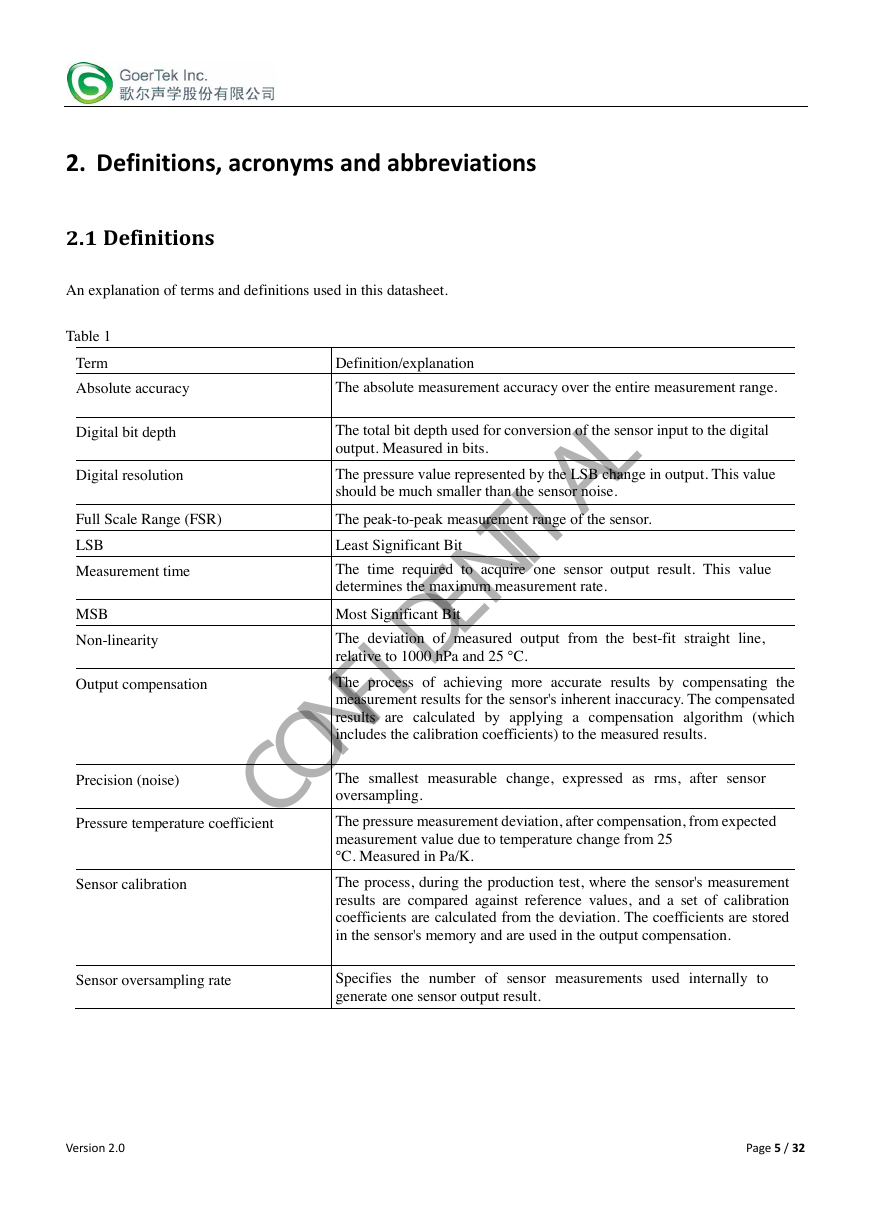
An explanation of terms and definitions used in this datasheet.
Table 1
Term
Definition/explanation
Absolute accuracy
The absolute measurement accuracy over the entire measurement range.
Digital bit depth
Digital resolution
The total bit depth used for conversion of the sensor input to the digital
output. Measured in bits.
The pressure value represented by the LSB change in output. This value
should be much smaller than the sensor noise.
Full Scale Range (FSR)
The peak-to-peak measurement range of the sensor.
LSB
Measurement time
MSB
Non-linearity
Output compensation
Precision (noise)
Pressure temperature coefficient
Sensor calibration
Least Significant Bit
The time required to acquire one sensor output result. This value
determines the maximum measurement rate.
Most Significant Bit
The deviation of measured output from the best-fit straight line,
relative to 1000 hPa and 25 °C.
The process of achieving more accurate results by compensating the
measurement results for the sensor's inherent inaccuracy. The compensated
results are calculated by applying a compensation algorithm (which
includes the calibration coefficients) to the measured results.
The smallest measurable change, expressed as rms, after sensor
oversampling.
The pressure measurement deviation, after compensation, from expected
measurement value due to temperature change from 25
°C. Measured in Pa/K.
The process, during the production test, where the sensor's measurement
results are compared against reference values, and a set of calibration
coefficients are calculated from the deviation. The coefficients are stored
in the sensor's memory and are used in the output compensation.
Sensor oversampling rate
Specifies the number of sensor measurements used internally to
generate one sensor output result.
Version 2.0
Page 5 / 32
CONFIDENTIAL�
3. Pin Configuration and Block Diagram
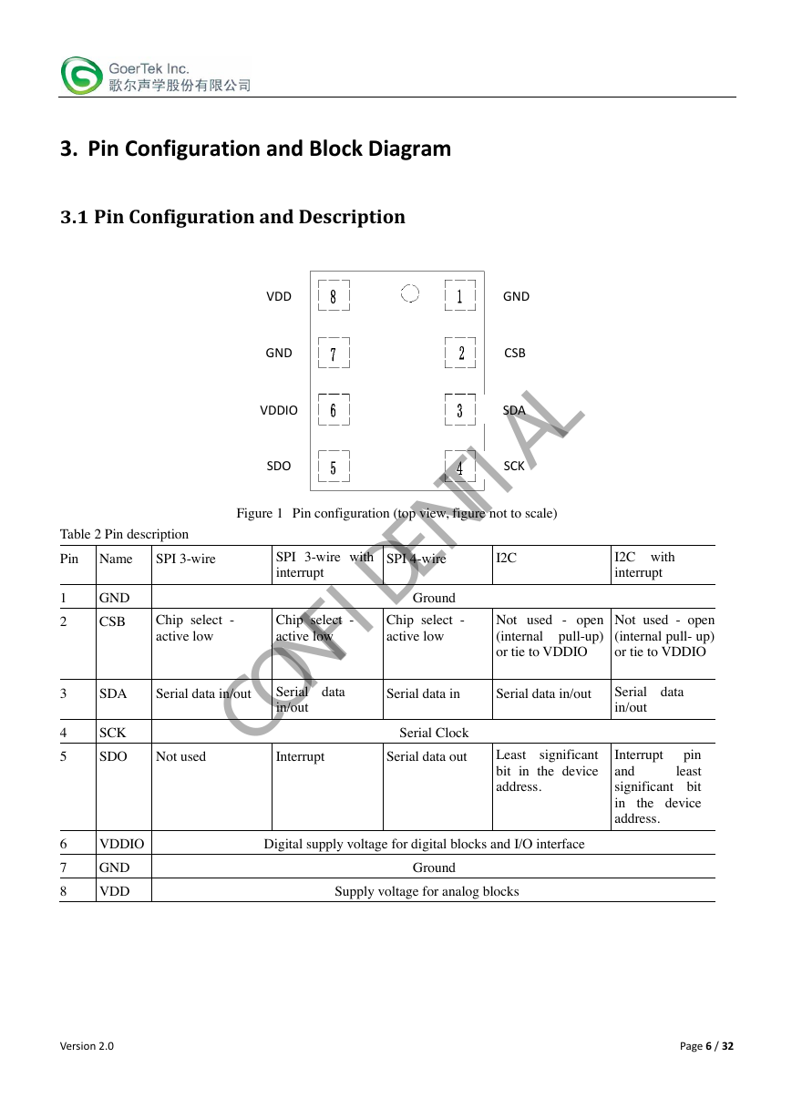
3.1 Pin Configuration and Description
VDD
GND
VDDIO
SDO
GND
CSB
SDA
SCK
Figure 1 Pin configuration (top view, figure not to scale)
SPI 3-wire with
interrupt
SPI 4-wire
I2C
I2C with
interrupt
Ground
Chip select -
active low
Chip select -
active low
Chip select -
active low
Not used - open
(internal pull-up)
or tie to VDDIO
Not used - open
(internal pull- up)
or tie to VDDIO
SDA
Serial data in/out
Serial data
in/out
Serial data in
Serial data in/out
SCK
Serial Clock
SDO
Not used
Interrupt
Serial data out
Least significant
bit in the device
address.
Serial data
in/out
pin
Interrupt
least
and
significant bit
in
the device
address.
VDDIO
GND
VDD
Digital supply voltage for digital blocks and I/O interface
Ground
Supply voltage for analog blocks
Table 2 Pin description
Pin Name
SPI 3-wire
GND
CSB
1
2
3
4
5
6
7
8
Version 2.0
Page 6 / 32
CONFIDENTIAL�
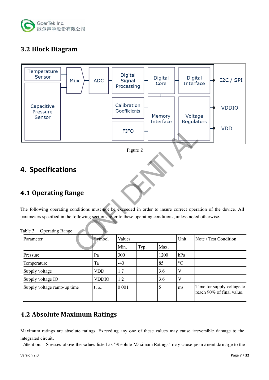
3.2 Block Diagram
4. Specifications
4.1 Operating Range
Figure 2
The following operating conditions must not be exceeded in order to insure correct operation of the device. All
parameters specified in the following sections refer to these operating conditions, unless noted otherwise.
Table 3 Operating Range
Parameter
Symbol
Values
Unit
Note / Test Condition
Min.
Typ.
Max.
Pressure
Temperature
Supply voltage
Supply voltage IO
Pa
Ta
VDD
VDDIO
300
-40
1.7
1.2
Supply voltage ramp-up time
tvddup
0.001
1200
hPa
85
3.6
3.6
5
°C
V
V
ms
Time for supply voltage to
reach 90% of final value.
4.2 Absolute Maximum Ratings
Maximum ratings are absolute ratings. Exceeding any one of these values may cause irreversible damage to the
integrated circuit.
Attention: Stresses above the values listed as "Absolute Maximum Ratings" may cause permanent damage to the
Version 2.0
Page 7 / 32
CONFIDENTIAL�


 2023年江西萍乡中考道德与法治真题及答案.doc
 2012年重庆南川中考生物真题及答案.doc
 2013年江西师范大学地理学综合及文艺理论基础考研真题.doc
 2020年四川甘孜小升初语文真题及答案I卷.doc
 2020年注册岩土工程师专业基础考试真题及答案.doc
 2023-2024学年福建省厦门市九年级上学期数学月考试题及答案.doc
 2021-2022学年辽宁省沈阳市大东区九年级上学期语文期末试题及答案.doc
 2022-2023学年北京东城区初三第一学期物理期末试卷及答案.doc
 2018上半年江西教师资格初中地理学科知识与教学能力真题及答案.doc
 2012年河北国家公务员申论考试真题及答案-省级.doc
 2020-2021学年江苏省扬州市江都区邵樊片九年级上学期数学第一次质量检测试题及答案.doc
 2022下半年黑龙江教师资格证中学综合素质真题及答案.doc