IETE Technical Review
ISSN: 0256-4602 (Print) 0974-5971 (Online) Journal homepage: https://www.tandfonline.com/loi/titr20
Design and Validation of Fractional-Order Control
Scheme for DC Servomotor via Internal Model
Control Approach
Sahaj Saxena & Yogesh V. Hote
To cite this article: Sahaj Saxena & Yogesh V. Hote (2019) Design and Validation of Fractional-
Order Control Scheme for DC Servomotor via Internal Model Control Approach, IETE Technical
Review, 36:1, 49-60, DOI: 10.1080/02564602.2017.1396935
To link to this article: https://doi.org/10.1080/02564602.2017.1396935
Published online: 06 Dec 2017.
Submit your article to this journal
Article views: 134
View Crossmark data
Citing articles: 2 View citing articles
Full Terms & Conditions of access and use can be found at
https://www.tandfonline.com/action/journalInformation?journalCode=titr20
�
IETE TECHNICAL REVIEW
2019, VOL. 36, NO. 1, 49–60
https://doi.org/10.1080/02564602.2017.1396935
Design and Validation of Fractional-Order Control Scheme for DC Servomotor via
Internal Model Control Approach
Sahaj Saxena
and Yogesh V. Hote
Department of Electrical Engineering, Indian Institute of Technology Roorkee, Roorkee, India
ABSTRACT
This paper proposes a robust fractional-order controller for DC servomotor using internal model
control and CRONE (Commande Robuste d’Ordre Non Entier) principle. The controller acquires a
PID (proportional-integral-derivative) form followed by a fractional-order integrator. Unlike the
conventional fractional-order PID controller which demands five tuning parameters, the proposed
scheme has only two tuning parameters which can be obtained on the basis of desired gain
crossover frequency and phase margin. For speed control problem, the performance of the
proposed controller is studied on hardware set up called precision modular servo system. The
proposed controller outperforms in terms of robustness and optimality when compared with
controllers designed by integer-order technique. Furthermore, the proposed scheme is applied for
position control problem and validated on QUBE-Servo 2 set up.
KEYWORDS
Fractional-order controller;
Gain crossover frequency;
Internal model control; Phase
margin; PID control;
Servomotor
1. INTRODUCTION
etc.
The DC servomotor has been used as a classical control
example for nearly half a century because it is a standard
i.e.
second-order system with stable characteristics (
speed-torque characteristics are well suited with most
mechanical loads) and has high industrial applicability
(particularly in performance drives of rolling mills,
machine tools, traction, robotics,
). Many control
ideas have been developed and illustrated for this sys-
tem, such as pulse width modulation and thyristor based
control [1,2], variable structure system control [3,4],
optimal control based on Pontryagin’s minimum princi-
ple [5], H1 control [6], minimum energy point-to-point
motion planning control [7], adaptive control [8], neural
network [9,10], Fuzzy PID [11], feedback linearization
scheme [12], estimation of distribution scheme [13], dis-
turbance observer scheme [14], model predictive control
[15,16], model-free control [17], algebraic derivation
estimation-based control [18],
integral retarded algo-
rithm [19], stability boundary locus [20] and reduced
modeling [21] based PID tunings and many more.
Interest in the DC servomotor control has been renewed
when recent developments have been made in the field
of fractional-order control theory. Actually, the frac-
tional-order controller is more flexible and gives a
chance to improve dynamic properties of the fractional-
order control system. In this regard, some control tech-
niques have been proposed and verified experimentally
for the tracking control and load regulation of the DC
© 2019 IETE
servomotor [22–28]. These controller schemes are based
on reset control, state feedback control, model reference
and fractional-order PID controller tuned via specified
gain and phase margins. Since fractional calculus
requires a lot of mathematical analysis, manipulations
and approximations, therefore the above stated frac-
tional-order controller strategies are complex in nature.
Thus, it could be challenging task when their synthesis
and implementation come into the picture.
Having these facts in mind, our goal is to design a robust
fractional-order controller through simple approach
without dealing with complex mathematical computa-
tion and synthesis method. Our work is motivated by
the precious work of Ma^amar & Rachid [29] which
bridges internal model control (IMC) and CRONE prin-
ciples to derive fractional-order controller similar to PID
form. Although the work of [29] opens a new dimension
to produce a simple analytical fractional-order PID for
first- and second-order stable minimum and non-mini-
mum phase plant, however the hardware validation is
still missing in literature.
In this paper, we deal with speed and position control
problem of DC servomotor using fractional-order con-
troller which includes PID controller and a fractional-
order integrator. The proposed controller synthesis relies
on CRONE approach and the popular IMC strategy
which has a rich history [30–32]. On one hand, CRONE
approach guarantees the phase flatness condition,
the
i.e.
�
50
S. SAXENA AND Y. V. HOTE: DESIGN AND VALIDATION OF FRACTIONAL-ORDER CONTROL SCHEME
phase of the loop transfer function is flat at the gain
crossover frequency thereby guaranteeing the invariance
of the phase margin with respect to the process DC-gain
variation such as pay-load, amplifier feed forward gain
and the load current/resistance in power systems. On
the other hand through IMC strategy, the PID controller
is tuned by a single parameter unlike three parameters
in traditional PID controllers. Also, on the contrary to
the conventional fractional-order PID controllers which
require five parameters, the proposed scheme requires
only two tuning parameters. The tuning law is based on
the desired gain crossover frequency and phase margin.
The proposed scheme is verified experimentally on hard-
ware set-up of DC servomotor for speed control prob-
lem. It is observed that the dynamic properties of the
closed-loop with the proposed fractional-order control-
ler are better than that of the closed-loop with the inte-
ger-order controller. Moreover, the controller brings
optimality in terms of integral error specification. The
proposed scheme is further extended to position control
problem and validated on QUBE-Servo 2 set up.
The other contribution in this paper comes in the form of
evaluation of the robustness of the control
loop. We
know that the CRONE control principle yields robustness
against plant perturbation but the limit of the plant
uncertainty is not directly evaluated through this method.
To fulfill this gap, we have derived the condition which
provides the limit of uncertainty in the plant gain varia-
tion to maintain the robust performance of controller.
2. PROBLEM FORMULATION
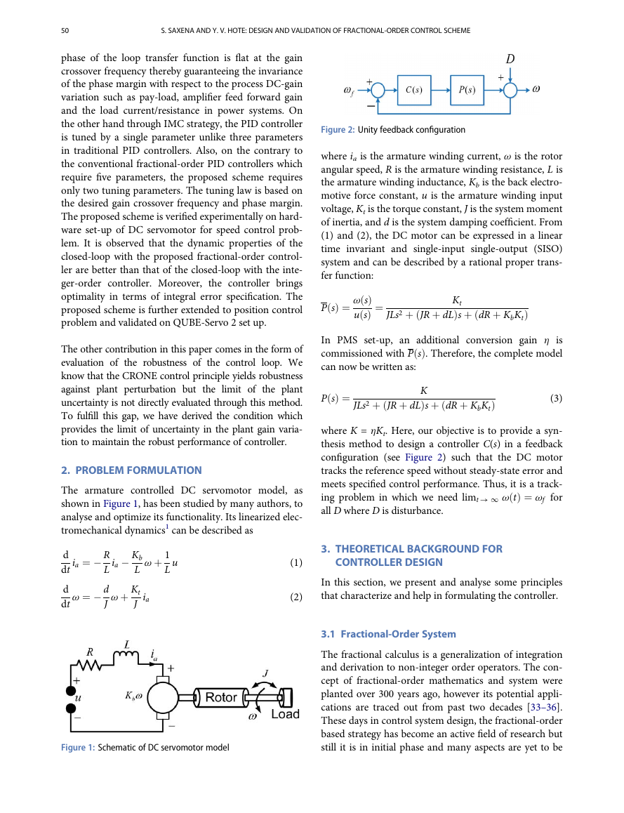
The armature controlled DC servomotor model, as
shown in Figure 1, has been studied by many authors, to
analyse and optimize its functionality. Its linearized elec-
tromechanical dynamics1 can be described as
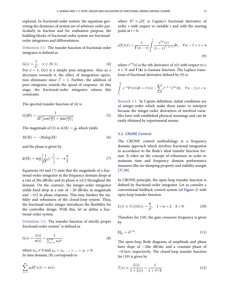
Figure 2: Unity feedback configuration
where ia is the armature winding current, v is the rotor
angular speed, R is the armature winding resistance, L is
the armature winding inductance, Kb is the back electro-
motive force constant, u is the armature winding input
voltage, Kt is the torque constant, J is the system moment
of inertia, and d is the system damping coefficient. From
(1) and (2), the DC motor can be expressed in a linear
time invariant and single-input single-output (SISO)
system and can be described by a rational proper trans-
fer function:
P sð Þ ¼ v sð Þ
u sð Þ ¼
Kt
JLs2 þ JR þ dL
Þs þ dR þ KbKt
ð
ð
Þ
In PMS set-up, an additional conversion gain h is
commissioned with P sð Þ. Therefore, the complete model
can now be written as:
P sð Þ ¼
K
Þs þ dR þ KbKt
JLs2 þ JR þ dL
(3)
ð
ð
Þ
where K = hKt. Here, our objective is to provide a syn-
thesis method to design a controller C(s) in a feedback
configuration (see Figure 2) such that the DC motor
tracks the reference speed without steady-state error and
meets specified control performance. Thus, it is a track-
ing problem in which we need limt ! 1 v tð Þ ¼ vf for
all D where D is disturbance.
d
dt
d
dt
ia ¼ � R
L
v ¼ � d
J
ia � Kb
L
v þ Kt
J
v þ 1
L
u
ia
3. THEORETICAL BACKGROUND FOR
CONTROLLER DESIGN
In this section, we present and analyse some principles
that characterize and help in formulating the controller.
(1)
(2)
3.1 Fractional-Order System
The fractional calculus is a generalization of integration
and derivation to non-integer order operators. The con-
cept of fractional-order mathematics and system were
planted over 300 years ago, however its potential appli-
cations are traced out from past two decades [33–36].
These days in control system design, the fractional-order
based strategy has become an active field of research but
still it is in initial phase and many aspects are yet to be
Figure 1: Schematic of DC servomotor model
�
S. SAXENA AND Y. V. HOTE: DESIGN AND VALIDATION OF FRACTIONAL-ORDER CONTROL SCHEME
51
explored. In fractional-order system, the equations gov-
erning the dynamics of system are of arbitrary order par-
ticularly in fraction and for realization purpose, the
building blocks of fractional-order system are fractional-
order integrators and differentiators.
Definition 3.1: The transfer function of fractional-order
integrator is defined as
; x 2 0; 1ð
Þ:
G sð Þ ¼ 1
(4)
sx
For x = 1, G(s) is a simple pure integrator. Also as x
decreases towards 0, the effect of integration opera-
tion eliminates since s0 = 1. Further, the addition of
pure integrator retards the speed of response. At this
stage,
this
the
constraint.
fractional-order
integrator
relaxes
The spectral transfer function of (4) is
G jVð
� � þ jsin xp
� �
Þ ¼
Vx cos xp
2
�
�
1
2
Þ ¼ 1
Vx which yields
The magnitude of (5) is A Vð
M Vð
Þ ¼ �20xlog Vð
Þ
�
�
and the phase is given by
f Vð
Þ ¼ arg
�x
1
Vx j
¼ �x
p
2
(5)
(6)
(7)
Equations (6) and (7) state that the magnitude of a frac-
tional-order integrator in the frequency domain drops at
a rate of 20x dB/dec and its phase is xp/2 throughout the
domain. On the contrary, the integer-order integrator
yields fixed drop at a rate of ¡20 dB/dec in magnitude
and ¡p/2 in phase response. This may hinders the sta-
bility and robustness of the closed-loop system. Thus,
the fractional-order integer introduces the flexibility for
the controller design. With this, let us define a frac-
tional-order system.
Definition 3.2: The transfer function of strictly proper
fractional-order system2 is defined as
1P
m
i¼1 aisyi
G sð Þ ¼ z sð Þ
w sð Þ ¼
where am 6¼ 0 and ym > ym ¡ 1 > ... > y1 > 0.
In time domain, (8) corresponds to
Xm
t z tð Þ ¼ w tð Þ
aiDyi
i¼1
(8)
where Dv � 0Dv
is Caputo’s fractional derivative of
order v with respect to variable t and with the starting
point at t = 0:
t
t z tð Þ ¼
0Dv
1
G n � v
ð
Þ
Z t
0
z nð Þ tð Þ
Þv�n�1 dt; 8 n � 1 < v < n
t � t
ð
(9)
where z(n)(t) is the nth derivative of z(t) with respect to t,
n 2 N and G(�) is Gamma function. The Laplace trans-
form of fractional derivative defined by (9) is
Z1
�stDvz tð Þdt ¼ svz sð Þ �
sv�k�1z kð Þ
0ð Þ; 8 n � 1�v < n
Xn�1
k¼0
e
0
Remark 3.1: In Caputo definition, initial conditions are
of integer-order which make them easier to interpret
because the integer-order derivatives of involved varia-
bles have well-established physical meanings and can be
easily obtained by experimental means.
3.2 CRONE Control
The CRONE control methodology is a frequency
domain approach which involves fractional integration
in accordance to the Bode’s ideal transfer function for-
mat. It relies on the concept of robustness in order to
maintain time and frequency domain performance
measures like iso-damping property and stability margin
[37,38].
In CRONE principle, the open-loop transfer function is
defined by fractional-order integrator. Let us consider a
conventional feedback control system (of Figure 2) with
open-loop transfer function
L sð Þ � C sð ÞG sð Þ ¼ k
sa
; 1 < a < 2; k > 0:
(10)
Therefore for (10), the gain crossover frequency is given
by
Vgc ¼ k1=a:
(11)
The open-loop Bode diagrams of amplitude and phase
have slope of ¡20a dB/dec and a constant phase of
¡0.5ap, respectively. The closed-loop transfer function
for (10) is given by
T sð Þ � L sð Þ
1 þ L sð Þ ¼
1
1 þ sa=k
(12)
�
52
S. SAXENA AND Y. V. HOTE: DESIGN AND VALIDATION OF FRACTIONAL-ORDER CONTROL SCHEME
Remark 3.2: The order a and Vgc establish the over-
shoot and the speed of the output response, respectively.
Therefore for (12), T(s) has phase margin
f ¼ p 1 � 0:5a
which is independent of system gain k. Further, the spec-
tral transfer function of (12) is
(13)
Þ;
ð
�
T jVð
Þ ¼
�
� þ j Vasin ap
k
�
2
k þ Vacos ap
2
whose magnitude is given by
jT jVð
Þj ¼
q
ffiffiffiffiffiffiffiffiffiffiffiffiffiffiffiffiffiffiffiffiffiffiffiffiffiffiffiffiffiffiffiffiffiffiffiffiffiffiffiffiffiffiffiffiffi
k2 þ V2a þ 2kVacos ap
k
2
2
2
i.e.
sinap
2
Now, to investigate the behaviour in frequency domain,
we evaluate the resonance peak Mr = maxjT(jV)j at res-
ffiffiffiffiffiffiffiffiffiffiffiffiffiffiffiffiffiffiffiffiffiffiffiffiffiffiffiffiffiffiffiffiffiffiffiffiffiffiffiffiffiffiffiffiffi
q
onance frequency Vr. Here, jT(jV)j is maximum when
k2 þ V2a þ 2kVacos ap
�
its denominator term,
C is minimum. To obtain the minimum value of C, set
dV C ¼ 0 which yields Vr ¼ kjcos ap
j1
d
a. On substituting
this value in jT(jV)j, we get Mr ¼ 1
. Since Mr is an
indicative of maximum overshoot which is independent
of k and depends only on a. Thus, the CRONE principle
guarantees the robustness of controller against gain
uncertainties in the plant. Therefore, the closed-loop sys-
tem (12) could be used as reference model to design C(s)
according to desired performance specifications using
Vgc and f.
Remark 3.3: Unlike the popular robust H1 scheme where
over estimation is made in parametric uncertainty, this
CRONE control considers the genuine uncertainty and
thus explicitly ensures the robustness of the control loop.
3.3 IMC Scheme
The IMC strategy relies on the internal model principle
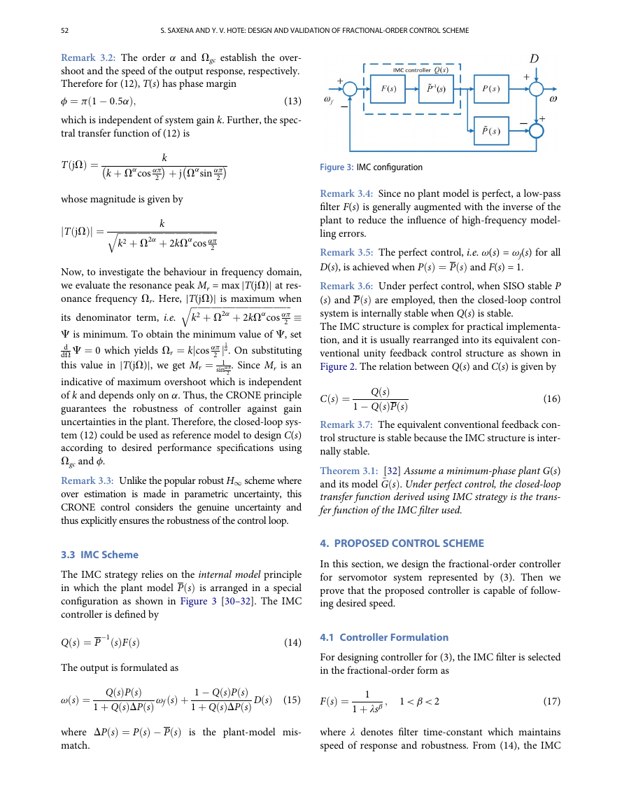
in which the plant model P sð Þ is arranged in a special
configuration as shown in Figure 3 [30–32]. The IMC
controller is defined by
Q sð Þ ¼ P
�1 sð ÞF sð Þ
(14)
The output is formulated as
1 þ Q sð ÞDP sð Þ vf sð Þ þ 1 � Q sð ÞP sð Þ
v sð Þ ¼ Q sð ÞP sð Þ
where DP sð Þ ¼ P sð Þ � P sð Þ is the plant-model mis-
match.
1 þ Q sð ÞDP sð Þ D sð Þ
(15)
Figure 3: IMC configuration
Remark 3.4: Since no plant model is perfect, a low-pass
filter F(s) is generally augmented with the inverse of the
plant to reduce the influence of high-frequency model-
ling errors.
i.e.
v(s) = vf(s) for all
Remark 3.5: The perfect control,
D(s), is achieved when P sð Þ ¼ P sð Þ and F(s) = 1.
Remark 3.6: Under perfect control, when SISO stable P
(s) and P sð Þ are employed, then the closed-loop control
system is internally stable when Q(s) is stable.
The IMC structure is complex for practical implementa-
tion, and it is usually rearranged into its equivalent con-
ventional unity feedback control structure as shown in
Figure 2. The relation between Q(s) and C(s) is given by
C sð Þ ¼
Q sð Þ
1 � Q sð ÞP sð Þ
(16)
Remark 3.7: The equivalent conventional feedback con-
trol structure is stable because the IMC structure is inter-
nally stable.
Theorem 3.1: [32] Assume a minimum-phase plant G(s)
and its model ~G sð Þ. Under perfect control, the closed-loop
transfer function derived using IMC strategy is the trans-
fer function of the IMC filter used.
4. PROPOSED CONTROL SCHEME
In this section, we design the fractional-order controller
for servomotor system represented by (3). Then we
prove that the proposed controller is capable of follow-
ing desired speed.
4.1 Controller Formulation
For designing controller for (3), the IMC filter is selected
in the fractional-order form as
F sð Þ ¼ 1
1 < b < 2
(17)
;
1 þ λsb
where λ denotes filter time-constant which maintains
speed of response and robustness. From (14), the IMC
�
S. SAXENA AND Y. V. HOTE: DESIGN AND VALIDATION OF FRACTIONAL-ORDER CONTROL SCHEME
53
controller is obtained as
ð
Q sð Þ ¼ JLs2 þ JR þ dL
Þ
ð
K 1 þ λsb
ð
Þs þ dR þ KbKt
Þ
ð
Substituting (18) in (16), we get
ð
Þs þ dR þ KbKt
C sð Þ ¼ JLs2 þ JR þ dL
�
Kλs
sg kp þ ki
� 1
s
Þ
�
1
sb�1
þ kds
(18)
(19)
where
g ¼ b � 1; kp ¼ JR þ dL
Kλ
; ki ¼ dR þ KbKt
Kλ
; kd ¼ JL
Kλ
(20)
Equation (19) yields controller which is a PID controller
cascaded with an additional fractional-order integrator.
4.2 Controller Tuning
i.e.
The controller in (19) has two unknown variables called
λ and g. To evaluate these tuning
tuning parameters,
parameter, Theorem 3.1 is employed which illustrates
that T(s) = F(s). Therefore, F(s) of (17) can be treated as
a reference model (12) for applying CRONE principle.
Now on comparing (17) with (12) , we have a = b and
k ¼ 1
λ. Upon substituting these values of a and k in (11)
and (13), the tuning parameter is obtained as
λ ¼ 1=Vb
Since, g = b ¡ 1, we have
g ¼ p � f
0:5p
� 1
(21)
(22)
gc
:
Thus, with the desired specifications Vgc and f, tuning
can be achieved.
4.3 Tracking Capability
Now, our goal
behaviour of the proposed controller.
is to observe and study the tracking
Corollary 4.1: Under the assumption of zero plant-model
mismatching, the steady-state error e(t) for unit step
input to the closed-loop system is zero when IMC filter
F(s) described in (17) is used to design IMC based
controller.
Proof: From Theorem 3.1, the complementary sensitiv-
the closed-loop transfer function is T(s)
ity function,
= F(s).
It
the sensitivity
i.e.
immediately follows that
function (transfer function from error signal to output)
S(s) � 1 ¡ T(s) is
S sð Þ ¼ λsb
1 þ λsb
(23)
S sð Þ
If E(s) be the Laplace transform of e(t) then
E sð Þ ¼ 1
s
On substituting (23) in (24) and applying “final value
theorem” of signal and systems [39], we get
t ! 1 e tð Þ ¼ lim
s! 0
sE sð Þ ¼ 0
(24)
(25)
lim
Thus, Corollary 4.1 proved that at steady-state, the error
signal converges to zero and the output follows the step
input. Hence,
this control scheme ensures (i) zero
steady-state error, (ii) iso-damping3 property of the
closed-loop step response and (iii) robustness against
process gain variation.
5. EXPERIMENTAL RESULTS
To illustrate the efficiency of the proposed methodology,
the experiment is performed on a laboratory-scale set-up
called PMS system developed by Feedback Instruments
Limited, UK. The set-up allows testing of designed con-
trollers in real time in Hardware-in-Loop configuration.
5.1 System description
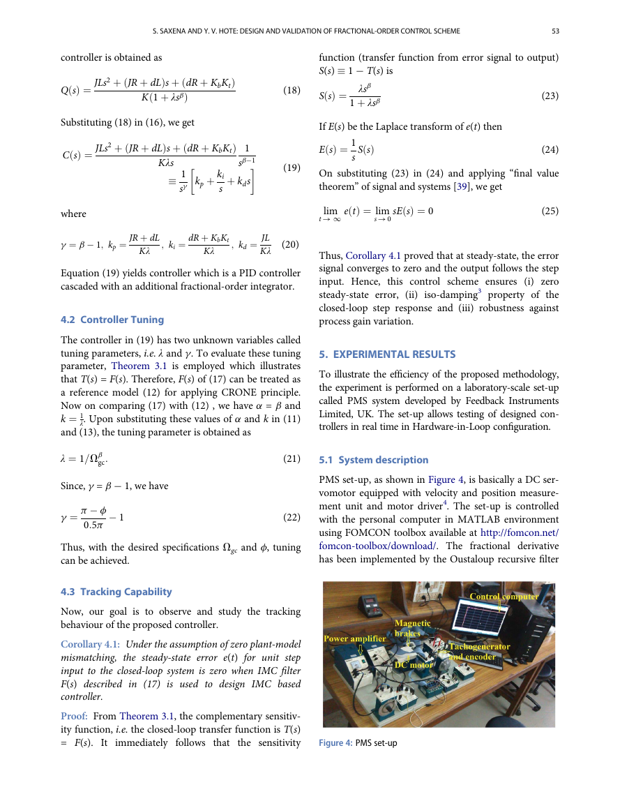
PMS set-up, as shown in Figure 4, is basically a DC ser-
vomotor equipped with velocity and position measure-
ment unit and motor driver4. The set-up is controlled
with the personal computer in MATLAB environment
using FOMCON toolbox available at http://fomcon.net/
fomcon-toolbox/download/. The fractional derivative
has been implemented by the Oustaloup recursive filter
Figure 4: PMS set-up
�
54
S. SAXENA AND Y. V. HOTE: DESIGN AND VALIDATION OF FRACTIONAL-ORDER CONTROL SCHEME
approximation5 choosing a frequency range of [Vl, Vh]
¡3, 103] rad/s and order of filter N = 5. The maxi-
= [10
mum value of control signal from computer is ¡2.5V to
+2.5V. The motor used is a 24V DC brushed motor with
a no-load maximum speed of 4050 rpm and nominal
torque at 2A is in the order of 0.1 N-m. The typical val-
ues of the parameters of the DC motors are as follows:
J = 140 £ 10
¡7 kg m2, Kt = 0.052 Nm/A, Kb =
¡6 Nms/rad, R = 2.5V, L =2.5 mH,
0.057 Vs/rad, d = 10
and h = 288/p. We want to apply the proposed method-
ology by considering following specifications: (1) Vgc =
1 rad/s and (2) f = p/3.
5.2 Performance Analysis
On substituting the parameters of motor defined in (19),
we obtained the proposed controller in which we get λ =
1 and g ¼ 1
3 from (21) and (22), respectively. To test the
efficiency of controller, PID controller is designed using
conventional IMC approach [30]. The controller param-
eters are enlisted in Table 1. The performance of control-
Table 1: Controller parameters
Method
Proposed
IMC
kp
7.3421 £ 10
7.3 £ 10
¡3
¡6
ki
6.2232 £ 10
¡4
0.6223
kd
7.3421 £ 10
¡9
7.3421 £ 10
¡6
FO-IMC
IMC
0.5
1
1.5
t (s)
(a)
2
2.5
3
FO-IMC
IMC
ler is tested for four different cases. In all the cases, the
reference speed vf is set to 1000 rad/s.
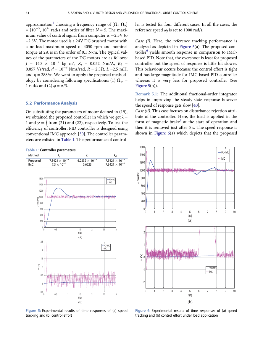
Case (i). Here, the reference tracking performance is
analysed as depicted in Figure 5(a). The proposed con-
troller6 yields smooth response in comparison to IMC-
based PID. Note that, the overshoot is least for proposed
controller but the speed of response is little bit slower.
This behaviour occurs because the control effort is tight
and has large magnitude for IMC-based PID controller
whereas it is very less for proposed controller (See
Figure 5(b)).
Remark 5.1: The additional fractional-order integrator
helps in improving the steady-state response however
the speed of response gets slow [40].
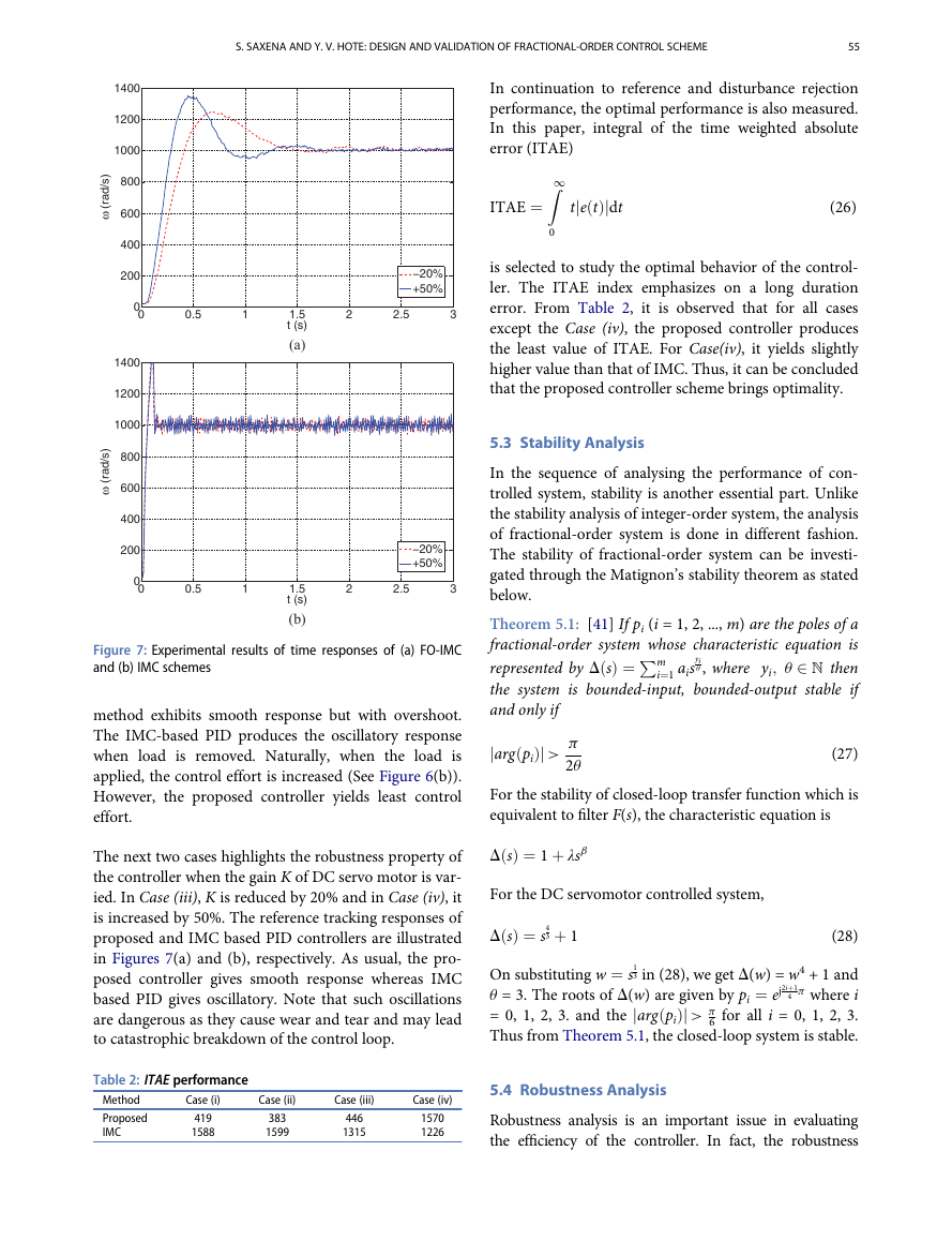
Case (ii). This case focuses on disturbance rejection attri-
bute of the controller. Here, the load is applied in the
form of magnetic brake7 at the start of operation and
then it is removed just after 5 s. The speed response is
shown in Figure 6(a) which depicts that the proposed
)
s
/
d
a
r
(
ω
1600
1400
1200
1000
800
600
400
200
0
0
FO-IMC
IMC
1
2
3
4
5
t (s)
(a)
6
7
8
9
10
)
V
(
u
2
1
0
-1
-2
FO-IMC
IMC
1600
1400
1200
1000
800
600
400
200
)
s
/
d
a
r
(
ω
0
0
2.5
2
1.5
)
V
(
u
1
0.5
0
-0.5
0
0.5
1
1.5
t (s)
(b)
2
2.5
3
0
1
2
3
4
5
t (s)
(b)
6
7
8
9
10
Figure 5: Experimental results of time responses of (a) speed
tracking and (b) control effort
Figure 6: Experimental results of time responses of (a) speed
tracking and (b) control effort under load application
�
S. SAXENA AND Y. V. HOTE: DESIGN AND VALIDATION OF FRACTIONAL-ORDER CONTROL SCHEME
55
1400
1200
1000
800
600
400
200
)
s
/
d
a
r
(
ω
0
0
0.5
1
1400
1200
1000
800
600
400
200
)
s
/
d
a
r
(
ω
0
0
0.5
1
1.5
t (s)
(a)
1.5
t (s)
(b)
In continuation to reference and disturbance rejection
performance, the optimal performance is also measured.
In this paper, integral of the time weighted absolute
error (ITAE)
Z1
ITAE ¼
tje tð Þjdt
(26)
−20%
+50%
2
2.5
3
−20%
+50%
2
2.5
3
0
is selected to study the optimal behavior of the control-
ler. The ITAE index emphasizes on a long duration
error. From Table 2, it is observed that for all cases
except the Case (iv), the proposed controller produces
the least value of ITAE. For Case(iv), it yields slightly
higher value than that of IMC. Thus, it can be concluded
that the proposed controller scheme brings optimality.
5.3 Stability Analysis
In the sequence of analysing the performance of con-
trolled system, stability is another essential part. Unlike
the stability analysis of integer-order system, the analysis
of fractional-order system is done in different fashion.
The stability of fractional-order system can be investi-
gated through the Matignon’s stability theorem as stated
below.
Figure 7: Experimental results of time responses of (a) FO-IMC
and (b) IMC schemes
method exhibits smooth response but with overshoot.
The IMC-based PID produces the oscillatory response
when load is removed. Naturally, when the load is
applied, the control effort is increased (See Figure 6(b)).
However, the proposed controller yields least control
effort.
The next two cases highlights the robustness property of
the controller when the gain K of DC servo motor is var-
ied. In Case (iii), K is reduced by 20% and in Case (iv), it
is increased by 50%. The reference tracking responses of
proposed and IMC based PID controllers are illustrated
in Figures 7(a) and (b), respectively. As usual, the pro-
posed controller gives smooth response whereas IMC
based PID gives oscillatory. Note that such oscillations
are dangerous as they cause wear and tear and may lead
to catastrophic breakdown of the control loop.
represented by D sð Þ ¼P
Theorem 5.1: [41] If pi (i = 1, 2, ..., m) are the poles of a
fractional-order system whose characteristic equation is
u , where yi; u 2 N then
the system is bounded-input, bounded-output stable if
and only if
jarg pið Þj >
yi
m
i¼1 ais
(27)
p
2u
For the stability of closed-loop transfer function which is
equivalent to filter F(s), the characteristic equation is
D sð Þ ¼ 1 þ λsb
3 þ 1
For the DC servomotor controlled system,
D sð Þ ¼ s4
On substituting w ¼ s1
3 in (28), we get D(w) = w4 + 1 and
u = 3. The roots of D(w) are given by pi ¼ ej2iþ1
p where i
= 0, 1, 2, 3. and the jarg pið Þj > p
6 for all i = 0, 1, 2, 3.
Thus from Theorem 5.1, the closed-loop system is stable.
(28)
4
Table 2: ITAE performance
Method
Proposed
IMC
419
1588
Case (i)
Case (ii)
Case (iii)
Case (iv)
383
1599
446
1315
1570
1226
5.4 Robustness Analysis
Robustness analysis is an important issue in evaluating
the efficiency of the controller. In fact, the robustness
�


 2023年江西萍乡中考道德与法治真题及答案.doc
 2012年重庆南川中考生物真题及答案.doc
 2013年江西师范大学地理学综合及文艺理论基础考研真题.doc
 2020年四川甘孜小升初语文真题及答案I卷.doc
 2020年注册岩土工程师专业基础考试真题及答案.doc
 2023-2024学年福建省厦门市九年级上学期数学月考试题及答案.doc
 2021-2022学年辽宁省沈阳市大东区九年级上学期语文期末试题及答案.doc
 2022-2023学年北京东城区初三第一学期物理期末试卷及答案.doc
 2018上半年江西教师资格初中地理学科知识与教学能力真题及答案.doc
 2012年河北国家公务员申论考试真题及答案-省级.doc
 2020-2021学年江苏省扬州市江都区邵樊片九年级上学期数学第一次质量检测试题及答案.doc
 2022下半年黑龙江教师资格证中学综合素质真题及答案.doc