ASME Y14.5-2009
[Revision of ASME Y14.5M-1994 (R2004)]
Dimensioning
and Tolerancing
Engineering Drawing and Related
Documentation Practices
A N I N T E R N A T I O N A L S T A N D A R D
Copyright ASME International Provided by IHS under license with ASME Licensee=FMC Technologies /5914950002 Not for Resale, 05/07/2009 00:24:44 MDTNo reproduction or networking permitted without license from IHS--`,,`,,,``,`,``,,``,`,`,,,`,`,`-`-`,,`,,`,`,,`---�
ASME Y14.5
ADOPTION NOTICE
ASME Y14.5, Dimensioning and Tolerancing, was adopted on 9 February 2009 for use by the Department of
Defense (DoD). Proposed changes by DoD activities must be submitted to the DoD Adopting Activity: Commander,
U.S. Army Research, Development and Engineering Center (ARDEC), ATTN: AMSRD-AAR-QES-E, Picatinny
Arsenal, NJ 07806-5000. Copies of this document may be purchased from The American Society of Mechanical
Engineers (ASME), 22 Law Drive, P.O. Box 2900, Fairfield, NJ 07007-2900, http://www.asme.org.
Adopting Activity:
Army — AR
(Project DRPR-2009-003)
Custodians:
Army — AR
Navy — SA
Air Force — 16
Review Activities:
Army — CR, IE, MI, PT, TM2
Navy — AS, CG, CH, EC, MC, NP, TD
Air Force — 13, 99
DLA — DH
OSD — SE
NSA — NS
Other — CM, MP, DC2
NOTE: The activities listed above were interested in this document as of the date
of this document. Since organizations and responsibilities can change, you should
verify the currency of the information above using the ASSIST Online database
at http://assist.daps.dla.mil.
AMSC N/A
AREA DRPR
DISTRIBUTION STATEMENT A. Approved for public release; distribution is unlimited.
Copyright ASME International Provided by IHS under license with ASME Licensee=FMC Technologies /5914950002 Not for Resale, 05/07/2009 00:24:44 MDTNo reproduction or networking permitted without license from IHS--`,,`,,,``,`,``,,``,`,`,,,`,`,`-`-`,,`,,`,`,,`---�
ASME Y14.5-2009
[Revision of ASME Y14.5M-1994 (R2004)]
Dimensioning and
Tolerancing
Engineering Drawing and Related
Documentation Practices
A N I N T E R N A T I O N A L S T A N D A R D
Copyright ASME International Provided by IHS under license with ASME Licensee=FMC Technologies /5914950002 Not for Resale, 05/07/2009 00:24:44 MDTNo reproduction or networking permitted without license from IHS--`,,`,,,``,`,``,,``,`,`,,,`,`,`-`-`,,`,,`,`,,`---�
Date of Issuance: March 27, 2009
This Standard will be revised when the Society approves the issuance of a new edition. There will be no addenda or
written interpretations of the requirements of this Standard issued to this edition.
Periodically certain actions of the ASME Y14 Committee may be published as Cases. Cases are published on the
ASME Web site under the Committee Pages at http://cstools.asme.org as they are issued.
ASME is the registered trademark of The American Society of Mechanical Engineers.
This code or standard was developed under procedures accredited as meeting the criteria for American National Standards. The
Standards Committee that approved the code or standard was balanced to assure that individuals from competent and concerned interests
have had an opportunity to participate. The proposed code or standard was made available for public review and comment that provides
an opportunity for additional public input from industry, academia, regulatory agencies, and the public-at-large.
ASME does not “approve,” “rate,” or “endorse” any item, construction, proprietary device, or activity.
ASME does not take any position with respect to the validity of any patent rights asserted in connection with any items mentioned in this
document, and does not undertake to insure anyone utilizing a standard against liability for infringement of any applicable letters patent,
nor assumes any such liability. Users of a code or standard are expressly advised that determination of the validity of any such patent rights,
and the risk of infringement of such rights, is entirely their own responsibility.
Participation by federal agency representative(s) or person(s) affiliated with industry is not to be interpreted as government or industry
endorsement of this code or standard.
ASME accepts responsibility for only those interpretations of this document issued in accordance with the established ASME procedures
and policies, which precludes the issuance of interpretations by individuals.
No part of this document may be reproduced in any form,
in an electronic retrieval system or otherwise,
without the prior written permission of the publisher.
The American Society of Mechanical Engineers
Three Park Avenue, New York, NY 10016-5990
THE AMERICAN SOCIETY OF MECHANICAL ENGINEERS
Copyright © 2009 by
All rights reserved
Printed in U.S.A.
Copyright ASME International Provided by IHS under license with ASME Licensee=FMC Technologies /5914950002 Not for Resale, 05/07/2009 00:24:44 MDTNo reproduction or networking permitted without license from IHS--`,,`,,,``,`,``,,``,`,`,,,`,`,`-`-`,,`,,`,`,,`---�
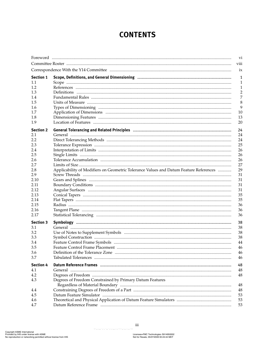
CONTENTS
Foreword ..............................................................................................................................................................................
vi
Committee Roster ................................................................................................................................................................ viii
Correspondence With the Y14 Committee ......................................................................................................................
ix
Scope, Definitions, and General Dimensioning ......................................................................................
Section 1
1
1
Scope ................................................................................................................................................................
1.1
1
References .......................................................................................................................................................
1.2
2
Definitions ......................................................................................................................................................
1.3
7
Fundamental Rules ........................................................................................................................................
1.4
1.5
Units of Measure ............................................................................................................................................
8
Types of Dimensioning .................................................................................................................................
1.6
9
10
Application of Dimensions ..........................................................................................................................
1.7
13
1.8
Dimensioning Features .................................................................................................................................
1.9
Location of Features ......................................................................................................................................
20
Section 2 General Tolerancing and Related Principles ..........................................................................................
24
24
General ............................................................................................................................................................
2.1
24
Direct Tolerancing Methods .........................................................................................................................
2.2
2.3
Tolerance Expression .....................................................................................................................................
25
26
Interpretation of Limits .................................................................................................................................
2.4
26
Single Limits ...................................................................................................................................................
2.5
26
Tolerance Accumulation ...............................................................................................................................
2.6
2.7
Limits of Size ....................................................................................................................................................
27
29
Applicability of Modifiers on Geometric Tolerance Values and Datum Feature References .............
2.8
31
Screw Threads ................................................................................................................................................
2.9
31
Gears and Splines ..........................................................................................................................................
2.10
2.11
Boundary Conditions ....................................................................................................................................
31
31
Angular Surfaces ...........................................................................................................................................
2.12
35
Conical Tapers ................................................................................................................................................
2.13
35
Flat Tapers .......................................................................................................................................................
2.14
36
Radius ..............................................................................................................................................................
2.15
2.16
Tangent Plane .................................................................................................................................................
36
36
Statistical Tolerancing ...................................................................................................................................
2.17
Symbology ..............................................................................................................................................
Section 3
38
38
General ............................................................................................................................................................
3.1
3.2
Use of Notes to Supplement Symbols ........................................................................................................
38
38
Symbol Construction .....................................................................................................................................
3.3
44
Feature Control Frame Symbols ..................................................................................................................
3.4
46
Feature Control Frame Placement ...............................................................................................................
3.5
3.6
Definition of the Tolerance Zone .................................................................................................................
46
46
Tabulated Tolerances .....................................................................................................................................
3.7
Section 4 Datum Reference Frames ........................................................................................................................
48
48
General ............................................................................................................................................................
4.1
4.2
Degrees of Freedom .......................................................................................................................................
48
Degrees of Freedom Constrained by Primary Datum Features
4.3
Regardless of Material Boundary ............................................................................................................
Constraining Degrees of Freedom of a Part ...............................................................................................
Datum Feature Simulator .............................................................................................................................
Theoretical and Physical Application of Datum Feature Simulators .....................................................
Datum Reference Frame ...............................................................................................................................
4.4
4.5
4.6
4.7
48
48
53
53
53
iii
Copyright ASME International Provided by IHS under license with ASME Licensee=FMC Technologies /5914950002 Not for Resale, 05/07/2009 00:24:44 MDTNo reproduction or networking permitted without license from IHS--`,,`,,,``,`,``,,``,`,`,,,`,`,`-`-`,,`,,`,`,,`---�
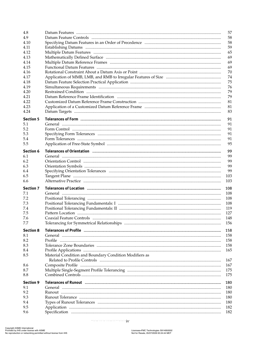
4.8
4.9
4.10
4.11
4.12
4.13
4.14
4.15
4.16
4.17
4.18
4.19
4.20
4.21
4.22
4.23
4.24
Section 5
5.1
5.2
5.3
5.4
5.5
Section 6
6.1
6.2
6.3
6.4
6.5
6.6
Section 7
7.1
7.2
7.3
7.4
7.5
7.6
7.7
Section 8
8.1
8.2
8.3
8.4
8.5
8.6
8.7
8.8
Section 9
9.1
9.2
9.3
9.4
9.5
9.6
57
Datum Features ..............................................................................................................................................
58
Datum Feature Controls ...............................................................................................................................
58
Specifying Datum Features in an Order of Precedence ...........................................................................
59
Establishing Datums .....................................................................................................................................
65
Multiple Datum Features .............................................................................................................................
69
Mathematically Defined Surface .................................................................................................................
69
Multiple Datum Reference Frames .............................................................................................................
69
Functional Datum Features ..........................................................................................................................
70
Rotational Constraint About a Datum Axis or Point ................................................................................
74
Application of MMB, LMB, and RMB to Irregular Features of Size ......................................................
75
Datum Feature Selection Practical Application .........................................................................................
76
Simultaneous Requirements ........................................................................................................................
79
Restrained Condition ....................................................................................................................................
79
Datum Reference Frame Identification ......................................................................................................
81
Customized Datum Reference Frame Construction .................................................................................
81
Application of a Customized Datum Reference Frame ...........................................................................
83
Datum Targets ................................................................................................................................................
Tolerances of Form ..................................................................................................................................
91
91
General ............................................................................................................................................................
91
Form Control ..................................................................................................................................................
91
Specifying Form Tolerances .........................................................................................................................
91
Form Tolerances .............................................................................................................................................
95
Application of Free-State Symbol ................................................................................................................
Tolerances of Orientation .......................................................................................................................
99
99
General ............................................................................................................................................................
99
Orientation Control .......................................................................................................................................
99
Orientation Symbols ......................................................................................................................................
Specifying Orientation Tolerances ..............................................................................................................
99
Tangent Plane ................................................................................................................................................. 103
Alternative Practice ....................................................................................................................................... 103
Tolerances of Location ............................................................................................................................ 108
General ............................................................................................................................................................ 108
Positional Tolerancing ................................................................................................................................... 108
Positional Tolerancing Fundamentals: I ..................................................................................................... 108
Positional Tolerancing Fundamentals: II .................................................................................................... 119
Pattern Location ............................................................................................................................................. 127
Coaxial Feature Controls .............................................................................................................................. 148
Tolerancing for Symmetrical Relationships ............................................................................................... 156
Tolerances of Profile ............................................................................................................................... 158
General ............................................................................................................................................................ 158
Profile .............................................................................................................................................................. 158
Tolerance Zone Boundaries .......................................................................................................................... 158
Profile Applications ....................................................................................................................................... 165
Material Condition and Boundary Condition Modifiers as
Related to Profile Controls ....................................................................................................................... 167
Composite Profile .......................................................................................................................................... 167
Multiple Single-Segment Profile Tolerancing ............................................................................................ 175
Combined Controls ......................................................................................................................................... 175
Tolerances of Runout .............................................................................................................................. 180
General ............................................................................................................................................................ 180
Runout ............................................................................................................................................................. 180
Runout Tolerance ........................................................................................................................................... 180
Types of Runout Tolerances ......................................................................................................................... 180
Application ..................................................................................................................................................... 182
Specification ................................................................................................................................................... 182
iv
Copyright ASME International Provided by IHS under license with ASME Licensee=FMC Technologies /5914950002 Not for Resale, 05/07/2009 00:24:44 MDTNo reproduction or networking permitted without license from IHS--`,,`,,,``,`,``,,``,`,`,,,`,`,`-`-`,,`,,`,`,,`---�
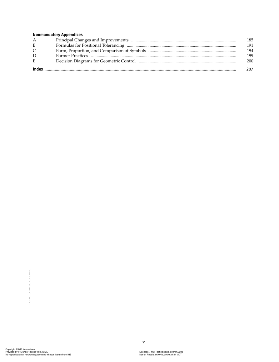
Nonmandatory Appendices
A
Principal Changes and Improvements .................................................................................................
B
Formulas for Positional Tolerancing .....................................................................................................
C
Form, Proportion, and Comparison of Symbols ..................................................................................
D
Former Practices ......................................................................................................................................
E
Decision Diagrams for Geometric Control ..........................................................................................
Index .....................................................................................................................................................................
185
191
194
199
200
207
v
Copyright ASME International Provided by IHS under license with ASME Licensee=FMC Technologies /5914950002 Not for Resale, 05/07/2009 00:24:44 MDTNo reproduction or networking permitted without license from IHS--`,,`,,,``,`,``,,``,`,`,,,`,`,`-`-`,,`,,`,`,,`---�
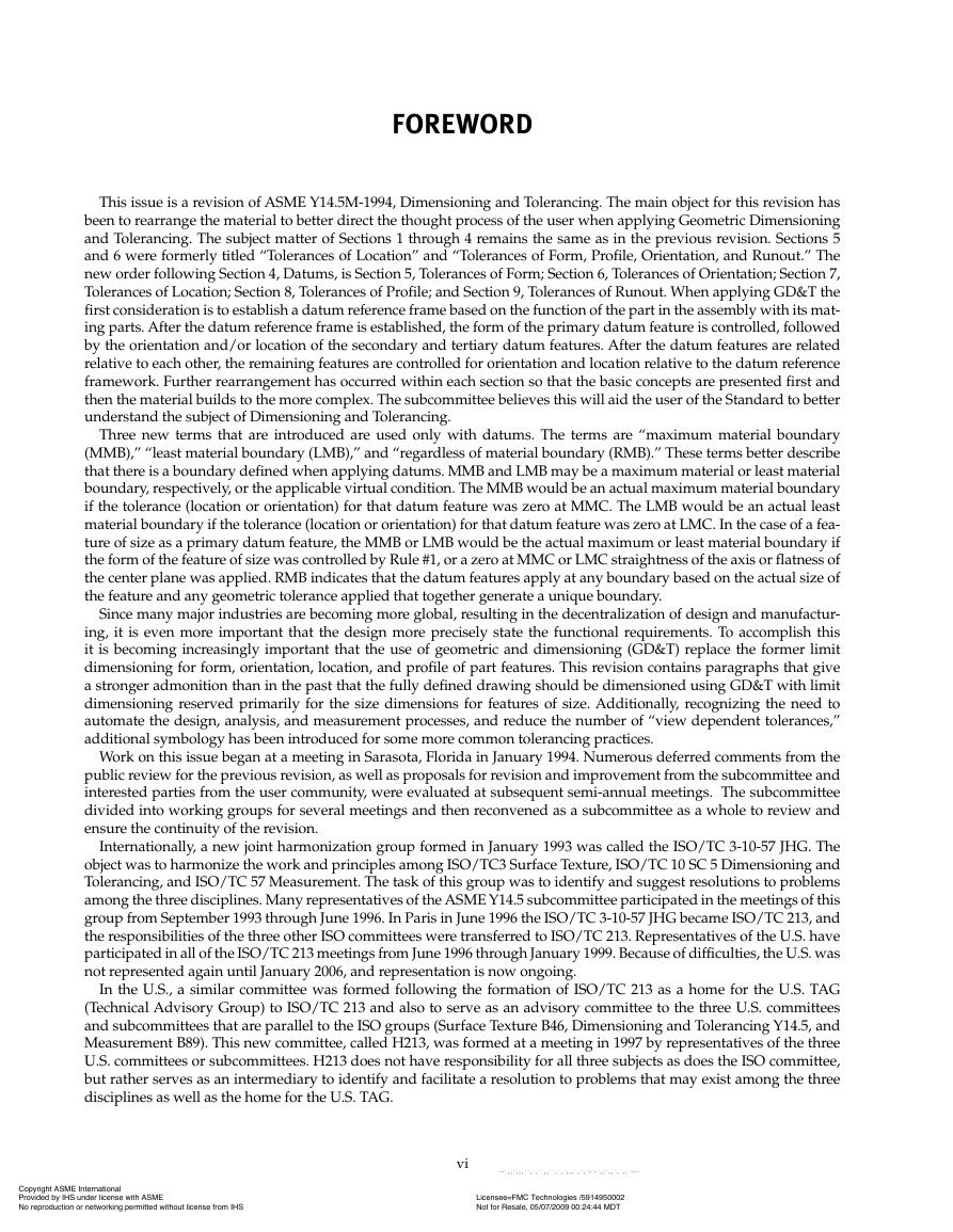
FOREWORD
This issue is a revision of ASME Y14.5M-1994, Dimensioning and Tolerancing. The main object for this revision has
been to rearrange the material to better direct the thought process of the user when applying Geometric Dimensioning
and Tolerancing. The subject matter of Sections 1 through 4 remains the same as in the previous revision. Sections 5
and 6 were formerly titled “Tolerances of Location” and “Tolerances of Form, Profile, Orientation, and Runout.” The
new order following Section 4, Datums, is Section 5, Tolerances of Form; Section 6, Tolerances of Orientation; Section 7,
Tolerances of Location; Section 8, Tolerances of Profile; and Section 9, Tolerances of Runout. When applying GD&T the
first consideration is to establish a datum reference frame based on the function of the part in the assembly with its mat-
ing parts. After the datum reference frame is established, the form of the primary datum feature is controlled, followed
by the orientation and/or location of the secondary and tertiary datum features. After the datum features are related
relative to each other, the remaining features are controlled for orientation and location relative to the datum reference
framework. Further rearrangement has occurred within each section so that the basic concepts are presented first and
then the material builds to the more complex. The subcommittee believes this will aid the user of the Standard to better
understand the subject of Dimensioning and Tolerancing.
Three new terms that are introduced are used only with datums. The terms are “maximum material boundary
(MMB),” “least material boundary (LMB),” and “regardless of material boundary (RMB).” These terms better describe
that there is a boundary defined when applying datums. MMB and LMB may be a maximum material or least material
boundary, respectively, or the applicable virtual condition. The MMB would be an actual maximum material boundary
if the tolerance (location or orientation) for that datum feature was zero at MMC. The LMB would be an actual least
material boundary if the tolerance (location or orientation) for that datum feature was zero at LMC. In the case of a fea-
ture of size as a primary datum feature, the MMB or LMB would be the actual maximum or least material boundary if
the form of the feature of size was controlled by Rule #1, or a zero at MMC or LMC straightness of the axis or flatness of
the center plane was applied. RMB indicates that the datum features apply at any boundary based on the actual size of
the feature and any geometric tolerance applied that together generate a unique boundary.
Since many major industries are becoming more global, resulting in the decentralization of design and manufactur-
ing, it is even more important that the design more precisely state the functional requirements. To accomplish this
it is becoming increasingly important that the use of geometric and dimensioning (GD&T) replace the former limit
dimensioning for form, orientation, location, and profile of part features. This revision contains paragraphs that give
a stronger admonition than in the past that the fully defined drawing should be dimensioned using GD&T with limit
dimensioning reserved primarily for the size dimensions for features of size. Additionally, recognizing the need to
automate the design, analysis, and measurement processes, and reduce the number of “view dependent tolerances,”
additional symbology has been introduced for some more common tolerancing practices.
Work on this issue began at a meeting in Sarasota, Florida in January 1994. Numerous deferred comments from the
public review for the previous revision, as well as proposals for revision and improvement from the subcommittee and
interested parties from the user community, were evaluated at subsequent semi-annual meetings. The subcommittee
divided into working groups for several meetings and then reconvened as a subcommittee as a whole to review and
ensure the continuity of the revision.
Internationally, a new joint harmonization group formed in January 1993 was called the ISO/TC 3-10-57 JHG. The
object was to harmonize the work and principles among ISO/TC3 Surface Texture, ISO/TC 10 SC 5 Dimensioning and
Tolerancing, and ISO/TC 57 Measurement. The task of this group was to identify and suggest resolutions to problems
among the three disciplines. Many representatives of the ASME Y14.5 subcommittee participated in the meetings of this
group from September 1993 through June 1996. In Paris in June 1996 the ISO/TC 3-10-57 JHG became ISO/TC 213, and
the responsibilities of the three other ISO committees were transferred to ISO/TC 213. Representatives of the U.S. have
participated in all of the ISO/TC 213 meetings from June 1996 through January 1999. Because of difficulties, the U.S. was
not represented again until January 2006, and representation is now ongoing.
In the U.S., a similar committee was formed following the formation of ISO/TC 213 as a home for the U.S. TAG
(Technical Advisory Group) to ISO/TC 213 and also to serve as an advisory committee to the three U.S. committees
and subcommittees that are parallel to the ISO groups (Surface Texture B46, Dimensioning and Tolerancing Y14.5, and
Measurement B89). This new committee, called H213, was formed at a meeting in 1997 by representatives of the three
U.S. committees or subcommittees. H213 does not have responsibility for all three subjects as does the ISO committee,
but rather serves as an intermediary to identify and facilitate a resolution to problems that may exist among the three
disciplines as well as the home for the U.S. TAG.
vi
Copyright ASME International Provided by IHS under license with ASME Licensee=FMC Technologies /5914950002 Not for Resale, 05/07/2009 00:24:44 MDTNo reproduction or networking permitted without license from IHS--`,,`,,,``,`,``,,``,`,`,,,`,`,`-`-`,,`,,`,`,,`---�


 2023年江西萍乡中考道德与法治真题及答案.doc
 2012年重庆南川中考生物真题及答案.doc
 2013年江西师范大学地理学综合及文艺理论基础考研真题.doc
 2020年四川甘孜小升初语文真题及答案I卷.doc
 2020年注册岩土工程师专业基础考试真题及答案.doc
 2023-2024学年福建省厦门市九年级上学期数学月考试题及答案.doc
 2021-2022学年辽宁省沈阳市大东区九年级上学期语文期末试题及答案.doc
 2022-2023学年北京东城区初三第一学期物理期末试卷及答案.doc
 2018上半年江西教师资格初中地理学科知识与教学能力真题及答案.doc
 2012年河北国家公务员申论考试真题及答案-省级.doc
 2020-2021学年江苏省扬州市江都区邵樊片九年级上学期数学第一次质量检测试题及答案.doc
 2022下半年黑龙江教师资格证中学综合素质真题及答案.doc