Chapter 1: LPC17xx Introductory information
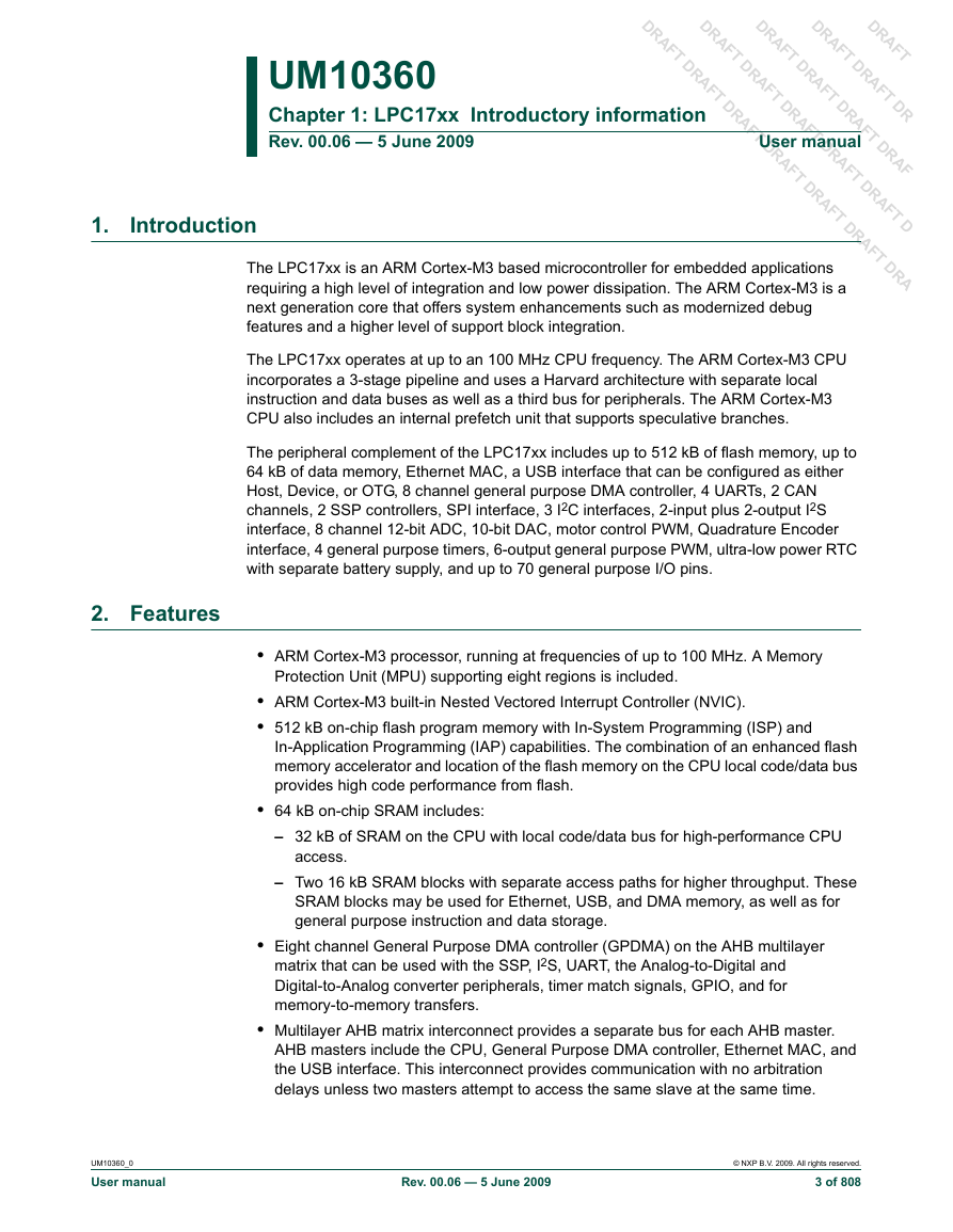
1. Introduction
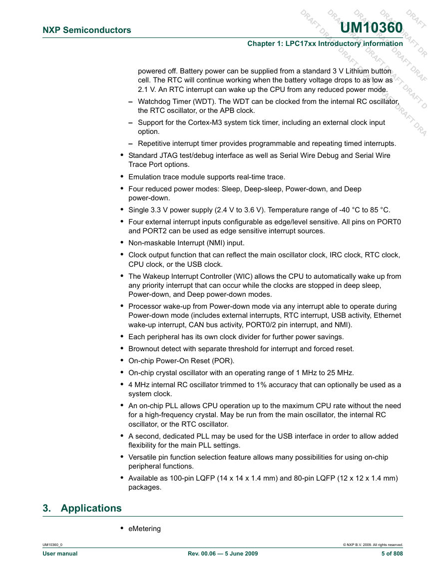
2. Features
3. Applications
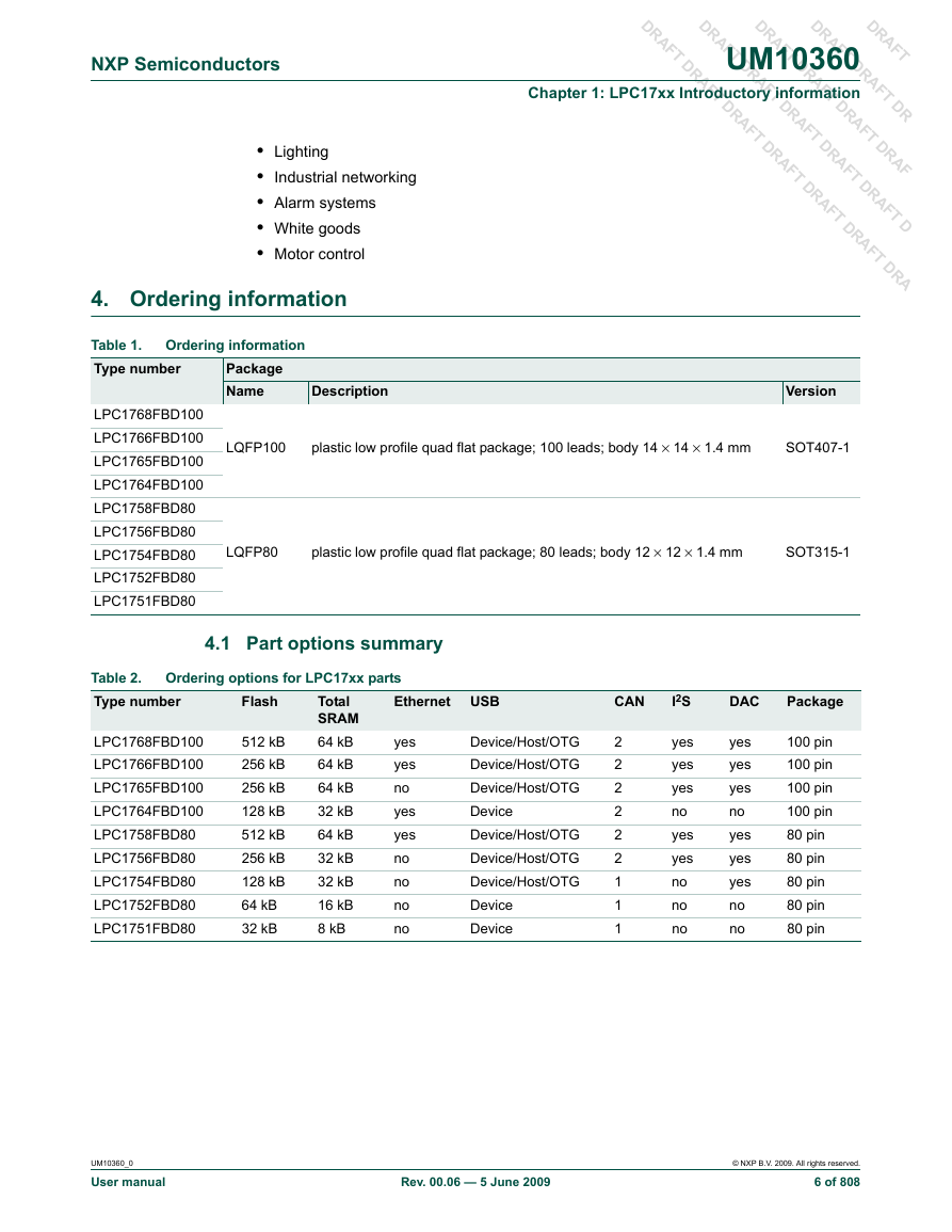
4. Ordering information
4.1 Part options summary
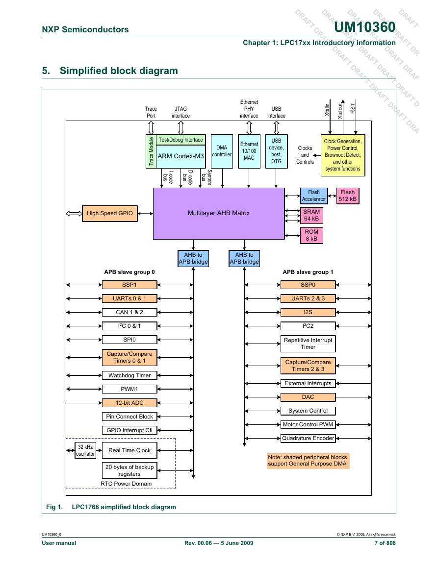
5. Simplified block diagram
6. Architectural overview
7. ARM Cortex-M3 processor
7.1 Cortex-M3 Configuration Options
8. On-chip flash memory system
9. On-chip Static RAM
10. Block diagram
Chapter 2: LPC17xx Memory map
1. Memory map and peripheral addressing
2. Memory maps
3. APB peripheral addresses
4. Memory re-mapping
5. Bus fault exceptions
Chapter 3: LPC17xx System control
1. Introduction
2. Pin description
3. Register description
4. Reset
4.1 Reset Source Identification Register (RSID - 0x400F C180)
5. Brown-out detection
6. External interrupt inputs
6.1 Register description
6.2 External Interrupt flag register (EXTINT - 0x400F C140)
6.3 External Interrupt Mode register (EXTMODE - 0x400F C148)
6.4 External Interrupt Polarity register (EXTPOLAR - 0x400F C14C)
7. Other system controls and status flags
7.1 System Controls and Status register (SCS - 0x400F C1A0)
Chapter 4: LPC17xx Clocking and power control
1. Summary of clocking and power control functions
2. Register description
3. Oscillators
3.1 Internal RC oscillator
3.2 Main oscillator
3.3 RTC oscillator
4. Clock source selection multiplexer
4.1 Clock Source Select register (CLKSRCSEL - 0x400F C10C)
5. PLL0 (Phase Locked Loop 0)
5.1 PLL0 operation
5.2 PLL0 register description
5.3 PLL0 Control register (PLL0CON - 0x400F C080)
5.4 PLL0 Configuration register (PLL0CFG - 0x400F C084)
5.5 PLL0 Status register (PLL0STAT - 0x400F C088)
5.6 PLL0 Interrupt: PLOCK0
5.7 PLL0 Modes
5.8 PLL0 Feed register (PLL0FEED - 0x400F C08C)
5.9 PLL0 and Power-down mode
5.10 PLL0 frequency calculation
5.11 Procedure for determining PLL0 settings
5.12 Examples of PLL0 settings
5.13 PLL0 setup sequence
6. PLL1 (Phase Locked Loop 1)
6.1 PLL1 register description
6.2 PLL1 Control register (PLL1CON - 0x400F C0A0)
6.3 PLL1 Configuration register (PLL1CFG - 0x400F C0A4)
6.4 PLL1 Status register (PLL1STAT - 0x400F C0A8)
6.5 PLL1 Interrupt: PLOCK1
6.6 PLL1 Feed register (PLL1FEED - 0x400F C0AC)
6.7 PLL1 and Power-down mode
6.8 PLL1 frequency calculation
6.9 Procedure for determining PLL1 settings
7. Clock dividers
7.1 CPU Clock Configuration register (CCLKCFG - 0x400F C104)
7.2 USB Clock Configuration register (USBCLKCFG - 0x400F C108)
7.3 IRC Trim Register (IRCTRIM - 0x400F C1A4)
7.4 Peripheral Clock Selection registers 0 and 1 (PCLKSEL0 - 0x400F C1A8 and PCLKSEL1 - 0x400F C1AC)
8. Power control
8.1 Sleep mode
8.2 Deep Sleep mode
8.3 Power-down mode
8.4 Deep Power-down mode
8.5 Peripheral power control
8.6 Register description
8.7 Power Mode Control register (PCON - 0x400F C0C0)
8.8 Wake-up from Reduced Power Modes
8.9 Power Control for Peripherals register (PCONP - 0x400F C0C4)
8.10 Power control usage notes
8.11 Power domains
9. Wake-up timer
10. External clock output pin
10.1 Clock Output Configuration register (CLKOUTCFG - 0x400F C1C8)
Chapter 5: LPC17xx Flash accelerator
1. Introduction
2. Flash accelerator blocks
2.1 Flash memory bank
2.2 Flash programming Issues
3. Register description
4. Flash Accelerator Configuration register (FLASHCFG - 0x400F C000)
5. Operation
Chapter 6: LPC17xx Nested Vectored Interrupt Controller (NVIC)
1. Features
2. Description
3. Interrupt sources
Chapter 7: LPC17xx Pin configuration
1. LPC17xx pin configuration
1.1 LPC17xx pin description
Chapter 8: LPC17xx Pin connect block
1. How to read this chapter
2. Description
3. Pin function select register values
4. Pin mode select register values
5. Register description
5.1 Pin Function Select register 0 (PINSEL0 - 0x4002 C000)
5.2 Pin Function Select Register 1 (PINSEL1 - 0x4002 C004)
5.3 Pin Function Select register 2 (PINSEL2 - 0x4002 C008)
5.4 Pin Function Select Register 3 (PINSEL3 - 0x4002 C00C)
5.5 Pin Function Select Register 4 (PINSEL4 - 0x4002 C010)
5.6 Pin Function Select Register 7 (PINSEL7 - 0x4002 C01C)
5.7 Pin Function Select Register 9 (PINSEL9 - 0x4002 C024)
5.8 Pin Function Select Register 10 (PINSEL10 - 0x4002 C028)
5.9 Pin Mode select register 0 (PINMODE0 - 0x4002 C040)
5.10 Pin Mode select register 1 (PINMODE1 - 0x4002 C044)
5.11 Pin Mode select register 2 (PINMODE2 - 0x4002 C048)
5.12 Pin Mode select register 3 (PINMODE3 - 0x4002 C04C)
5.13 Pin Mode select register 4 (PINMODE4 - 0x4002 C050)
5.14 Pin Mode select register 7 (PINMODE7 - 0x4002 C05C)
5.15 Pin Mode select register 9 (PINMODE9 - 0x4002 C064)
5.16 Open Drain Pin Mode select register 0 (PINMODE_OD0 - 0x4002 C068)
5.17 Open Drain Pin Mode select register 1 (PINMODE_OD1 - 0x4002 C06C)
5.18 Open Drain Pin Mode select register 2 (PINMODE_OD2 - 0x4002 C070)
5.19 Open Drain Pin Mode select register 3 (PINMODE_OD3 - 0x4002 C074)
5.20 Open Drain Pin Mode select register 4 (PINMODE_OD4 - 0x4002 C078)
5.21 I2C Pin Configuration register (I2CPADCFG - 0x4002 C07C)
Chapter 9: LPC17xx General Purpose Input/Output (GPIO)
1. Basic configuration
2. Features
2.1 Digital I/O ports
2.2 Interrupt generating digital ports
3. Applications
4. Pin description
5. Register description
5.1 GPIO port Direction register FIOxDIR (FIO0DIR to FIO4DIR- 0x2009 C000 to 0x2009 C080)
5.2 GPIO port output Set register FIOxSET (FIO0SET to FIO7SET - 0x2009 C018 to 0x2009 C098)
5.3 GPIO port output Clear register FIOxCLR (FIO0CLR to FIO7CLR- 0x2009 C01C to 0x2009 C09C)
5.4 GPIO port Pin value register FIOxPIN (FIO0PIN to FIO7PIN- 0x2009 C014 to 0x2009 C094)
5.5 Fast GPIO port Mask register FIOxMASK (FIO0MASK to FIO7MASK - 0x2009 C010 to 0x2009 C090)
5.6 GPIO interrupt registers
6. GPIO usage notes
6.1 Example: An instantaneous output of 0s and 1s on a GPIO port
6.2 Writing to FIOSET/FIOCLR vs. FIOPIN
Chapter 10: LPC17xx Ethernet
1. Basic configuration
2. Introduction
3. Features
4. Architecture and operation
5. DMA engine functions
6. Overview of DMA operation
7. Ethernet Packet
8. Overview
8.1 Partitioning
8.2 Example PHY Devices
9. Pin description
10. Registers and software interface
10.1 Register map
11. Ethernet MAC register definitions
11.1 MAC Configuration Register 1 (MAC1 - 0x5000 0000)
11.2 MAC Configuration Register 2 (MAC2 - 0x5000 0004)
11.3 Back-to-Back Inter-Packet-Gap Register (IPGT - 0x5000 0008)
11.4 Non Back-to-Back Inter-Packet-Gap Register (IPGR - 0x5000 000C)
11.5 Collision Window / Retry Register (CLRT - 0x5000 0010)
11.6 Maximum Frame Register (MAXF - 0x5000 0014)
11.7 PHY Support Register (SUPP - 0x5000 0018)
11.8 Test Register (TEST - 0x5000 001C)
11.9 MII Mgmt Configuration Register (MCFG - 0x5000 0020)
11.10 MII Mgmt Command Register (MCMD - 0x5000 0024)
11.11 MII Mgmt Address Register (MADR - 0x5000 0028)
11.12 MII Mgmt Write Data Register (MWTD - 0x5000 002C)
11.13 MII Mgmt Read Data Register (MRDD - 0x5000 0030)
11.14 MII Mgmt Indicators Register (MIND - 0x5000 0034)
11.15 Station Address 0 Register (SA0 - 0x5000 0040)
11.16 Station Address 1 Register (SA1 - 0x5000 0044)
11.17 Station Address 2 Register (SA2 - 0x5000 0048)
12. Control register definitions
12.1 Command Register (Command - 0x5000 0100)
12.2 Status Register (Status - 0x5000 0104)
12.3 Receive Descriptor Base Address Register (RxDescriptor - 0x5000 0108)
12.4 Receive Status Base Address Register (RxStatus - 0x5000 010C)
12.5 Receive Number of Descriptors Register (RxDescriptor - 0x5000 0110)
12.6 Receive Produce Index Register (RxProduceIndex - 0x5000 0114)
12.7 Receive Consume Index Register (RxConsumeIndex - 0x5000 0118)
12.8 Transmit Descriptor Base Address Register (TxDescriptor - 0x5000 011C)
12.9 Transmit Status Base Address Register (TxStatus - 0x5000 0120)
12.10 Transmit Number of Descriptors Register (TxDescriptorNumber - 0x5000 0124)
12.11 Transmit Produce Index Register (TxProduceIndex - 0x5000 0128)
12.12 Transmit Consume Index Register (TxConsumeIndex - 0x5000 012C)
12.13 Transmit Status Vector 0 Register (TSV0 - 0x5000 0158)
12.14 Transmit Status Vector 1 Register (TSV1 - 0x5000 015C)
12.15 Receive Status Vector Register (RSV - 0x5000 0160)
12.16 Flow Control Counter Register (FlowControlCounter - 0x5000 0170)
12.17 Flow Control Status Register (FlowControlStatus - 0x5000 0174)
13. Receive filter register definitions
13.1 Receive Filter Control Register (RxFilterCtrl - 0x5000 0200)
13.2 Receive Filter WoL Status Register (RxFilterWoLStatus - 0x5000 0204)
13.3 Receive Filter WoL Clear Register (RxFilterWoLClear - 0x5000 0208)
13.4 Hash Filter Table LSBs Register (HashFilterL - 0x5000 0210)
13.5 Hash Filter Table MSBs Register (HashFilterH - 0x5000 0214)
14. Module control register definitions
14.1 Interrupt Status Register (IntStatus - 0x5000 0FE0)
14.2 Interrupt Enable Register (IntEnable - 0x5000 0FE4)
14.3 Interrupt Clear Register (IntClear - 0x5000 0FE8)
14.4 Interrupt Set Register (IntSet - 0x5000 0FEC)
14.5 Power-Down Register (PowerDown - 0x5000 0FF4)
15. Descriptor and status formats
15.1 Receive descriptors and statuses
15.2 Transmit descriptors and statuses
16. Ethernet block functional description
16.1 Overview
16.2 AHB interface
17. Interrupts
17.1 Direct Memory Access (DMA)
17.2 Initialization
17.3 Transmit process
17.4 Receive process
17.5 Transmission retry
17.6 Status hash CRC calculations
17.7 Duplex modes
17.8 IEE 802.3/Clause 31 flow control
17.9 Half-Duplex mode backpressure
17.10 Receive filtering
17.11 Power management
17.12 Wake-up on LAN
17.13 Enabling and disabling receive and transmit
17.14 Transmission padding and CRC
17.15 Huge frames and frame length checking
17.16 Statistics counters
17.17 MAC status vectors
17.18 Reset
17.19 Ethernet errors
18. AHB bandwidth
18.1 DMA access
18.2 Types of CPU access
18.3 Overall bandwidth
19. CRC calculation
Chapter 11: LPC17xx USB device controller
1. How to read this chapter
2. Basic configuration
3. Introduction
4. Features
5. Fixed endpoint configuration
6. Functional description
6.1 Analog transceiver
6.2 Serial Interface Engine (SIE)
6.3 Endpoint RAM (EP_RAM)
6.4 EP_RAM access control
6.5 DMA engine and bus master interface
6.6 Register interface
6.7 SoftConnect
6.8 GoodLink
7. Operational overview
8. Pin description
9. Clocking and power management
9.1 Power requirements
9.2 Clocks
9.3 Power management support
9.4 Remote wake-up
10. Register description
10.1 Clock control registers
10.2 Device interrupt registers
10.3 Endpoint interrupt registers
10.4 Endpoint realization registers
10.5 USB transfer registers
10.6 SIE command code registers
10.7 DMA registers
11. Interrupt handling
12. Serial interface engine command description
12.1 Set Address (Command: 0xD0, Data: write 1 byte)
12.2 Configure Device (Command: 0xD8, Data: write 1 byte)
12.3 Set Mode (Command: 0xF3, Data: write 1 byte)
12.4 Read Current Frame Number (Command: 0xF5, Data: read 1 or 2 bytes)
12.5 Read Test Register (Command: 0xFD, Data: read 2 bytes)
12.6 Set Device Status (Command: 0xFE, Data: write 1 byte)
12.7 Get Device Status (Command: 0xFE, Data: read 1 byte)
12.8 Get Error Code (Command: 0xFF, Data: read 1 byte)
12.9 Read Error Status (Command: 0xFB, Data: read 1 byte)
12.10 Select Endpoint (Command: 0x00 - 0x1F, Data: read 1 byte (optional))
12.11 Select Endpoint/Clear Interrupt (Command: 0x40 - 0x5F, Data: read 1 byte)
12.12 Set Endpoint Status (Command: 0x40 - 0x55, Data: write 1 byte (optional))
12.13 Clear Buffer (Command: 0xF2, Data: read 1 byte (optional))
12.14 Validate Buffer (Command: 0xFA, Data: none)
13. USB device controller initialization
14. Slave mode operation
14.1 Interrupt generation
14.2 Data transfer for OUT endpoints
14.3 Data transfer for IN endpoints
15. DMA operation
15.1 Transfer terminology
15.2 USB device communication area
15.3 Triggering the DMA engine
15.4 The DMA descriptor
15.5 Non-isochronous endpoint operation
15.6 Isochronous endpoint operation
15.7 Auto Length Transfer Extraction (ATLE) mode operation
16. Double buffered endpoint operation
16.1 Bulk endpoints
16.2 Isochronous endpoints
Chapter 12: LPC17xx USB Host controller
1. How to read this chapter
2. Basic configuration
3. Introduction
3.1 Features
3.2 Architecture
4. Interfaces
4.1 Pin description
4.2 Software interface
Chapter 13: LPC17xx USB OTG controller
1. How to read this chapter
2. Basic configuration
3. Introduction
4. Features
5. Architecture
6. Modes of operation
7. Pin configuration
7.1 Connecting the USB port to an external OTG transceiver
7.2 Connecting USB as a host
7.3 Connecting USB as device
8. Register description
8.1 USB Interrupt Status Register (USBIntSt - 0x5000 C1C0)
8.2 OTG Interrupt Status Register (OTGIntSt - 0x5000 C100)
8.3 OTG Interrupt Enable Register (OTGIntEn - 0x5000 C104)
8.4 OTG Interrupt Set Register (OTGIntSet - 0x5000 C20C)
8.5 OTG Interrupt Clear Register (OTGIntClr - 0x5000 C10C)
8.6 OTG Status and Control Register (OTGStCtrl - 0x5000 C110)
8.7 OTG Timer Register (OTGTmr - 0x5000 C114)
8.8 OTG Clock Control Register (OTGClkCtrl - 0x5000 CFF4)
8.9 OTG Clock Status Register (OTGClkSt - 0x5000 CFF8)
8.10 I2C Receive Register (I2C_RX - 0x5000 C300)
8.11 I2C Transmit Register (I2C_TX - 0x5000 C300)
8.12 I2C Status Register (I2C_STS - 0x5000 C304)
8.13 I2C Control Register (I2C_CTL - 0x5000 C308)
8.14 I2C Clock High Register (I2C_CLKHI - 0x5000 C30C)
8.15 I2C Clock Low Register (I2C_CLKLO - 0x5000 C310)
8.16 Interrupt handling
9. HNP support
9.1 B-device: peripheral to host switching
9.2 A-device: host to peripheral HNP switching
10. Clocking and power management
10.1 Device clock request signals
10.2 Power-down mode support
11. USB OTG controller initialization
Chapter 14: LPC17xx UART0/2/3
1. Basic configuration
2. Features
3. Pin description
4. Register description
14.4.1 UARTn Receiver Buffer Register (U0RBR - 0x4000 C000, U2RBR - 0x4009 8000, U3RBR - 0x4009 C000 when DLAB = 0, Read Only)
4.2 UARTn Transmit Holding Register (U0THR - 0x4000 C000, U2THR - 0x4009 8000, U3THR - 0x4009 C000 when DLAB = 0, Write Only)
4.3 UARTn Divisor Latch LSB register (U0DLL - 0x4000 C000, U2DLL - 0x4009 8000, U3DLL - 0x4009 C000 when DLAB = 1) and UARTn Divisor Latch MSB register (U0DLM - 0x4000 C004, U2DLL - 0x4009 8004, U3DLL - 0x4009 C004 when DLAB = 1)
4.4 UARTn Interrupt Enable Register (U0IER - 0x4000 C004, U2IER - 0x4009 8004, U3IER - 0x4009 C004 when DLAB = 0)
4.5 UARTn Interrupt Identification Register (U0IIR - 0x4000 C008, U2IIR - 0x4009 8008, U3IIR - 0x4009 C008, Read Only)
4.6 UARTn FIFO Control Register (U0FCR - 0x4000 C008, U2FCR - 0x4009 8008, U3FCR - 0x4009 C008, Write Only)
4.7 UARTn Line Control Register (U0LCR - 0x4000 C00C, U2LCR - 0x4009 800C, U3LCR - 0x4009 C00C)
4.8 UARTn Line Status Register (U0LSR - 0x4000 C014, U2LSR - 0x4009 8014, U3LSR - 0x4009 C014, Read Only)
4.9 UARTn Scratch Pad Register (U0SCR - 0x4000 C01C, U2SCR - 0x4009 801C U3SCR - 0x4009 C01C)
4.10 UARTn Auto-baud Control Register (U0ACR - 0x4000 C020, U2ACR - 0x4009 8020, U3ACR - 0x4009 C020)
4.11 UARTn IrDA Control Register (U0ICR - 0x4000 C024, U2ICR - 0x4009 8024, U3ICR - 0x4009 C024)
4.12 UARTn Fractional Divider Register (U0FDR - 0x4000 C028, U2FDR - 0x4009 8028, U3FDR - 0x4009 C028)
4.13 UARTn Transmit Enable Register (U0TER - 0x4000 C030, U2TER - 0x4009 8030, U3TER - 0x4009 C030)
4.14 UARTn FIFO Level register (U0FIFOLVL - 0x4000 C058, U2FIFOLVL - 0x4009 8058, U3FIFOLVL - 0x4009 C058, Read Only)
5. Architecture
Chapter 15: LPC17xx UART1
1. Basic configuration
2. Features
3. Pin description
4. Register description
4.1 UART1 Receiver Buffer Register (U1RBR - 0x4001 0000, when DLAB = 0, Read Only)
4.2 UART1 Transmitter Holding Register (U1THR - 0x4001 0000 when DLAB = 0, Write Only)
4.3 UART1 Divisor Latch LSB and MSB Registers (U1DLL - 0x4001 0000 and U1DLM - 0x4001 0004, when DLAB = 1)
4.4 UART1 Interrupt Enable Register (U1IER - 0x4001 0004, when DLAB = 0)
4.5 UART1 Interrupt Identification Register (U1IIR - 0x4001 0008, Read Only)
4.6 UART1 FIFO Control Register (U1FCR - 0x4001 0008, Write Only)
4.7 UART1 Line Control Register (U1LCR - 0x4001 000C)
4.8 UART1 Modem Control Register (U1MCR - 0x4001 0010)
4.9 Auto-flow control
4.10 UART1 Line Status Register (U1LSR - 0x4001 0014, Read Only)
4.11 UART1 Modem Status Register (U1MSR - 0x4001 0018, Read Only)
4.12 UART1 Scratch Pad Register (U1SCR - 0x4001 001C)
4.13 UART1 Auto-baud Control Register (U1ACR - 0x4001 0020)
4.14 Auto-baud
4.15 Auto-baud modes
4.16 UART1 Fractional Divider Register (U1FDR - 0x4001 0028)
4.17 UART1 Transmit Enable Register (U1TER - 0x4001 0030)
4.18 UART1 RS485 Control register (U1RS485CTRL - 0x4001 004C)
4.19 UART1 RS-485 Address Match register (U1RS485ADRMATCH - 0x4001 0050)
4.20 UART1 RS-485 Delay value register (U1RS485DLY - 0x4001 0054)
4.21 RS-485/EIA-485 modes of operation
4.22 UART1 FIFO Level register (U1FIFOLVL - 0x4001 0058, Read Only)
5. Architecture
Chapter 16: LPC17xx CAN1/2
1. Basic configuration
2. CAN controllers
3. Features
3.1 General CAN features
3.2 CAN controller features
3.3 Acceptance filter features
4. Pin description
5. CAN controller architecture
5.1 APB Interface Block (AIB)
5.2 Interface Management Logic (IML)
5.3 Transmit Buffers (TXB)
5.4 Receive Buffer (RXB)
5.5 Error Management Logic (EML)
5.6 Bit Timing Logic (BTL)
5.7 Bit Stream Processor (BSP)
5.8 CAN controller self-tests
6. Memory map of the CAN block
7. CAN controller registers
7.1 CAN Mode register (CAN1MOD - 0x4004 4000, CAN2MOD - 0x4004 8000)
7.2 CAN Command Register (CAN1CMR - 0x4004 x004, CAN2CMR - 0x4004 8004)
7.3 CAN Global Status Register (CAN1GSR - 0x4004 x008, CAN2GSR - 0x4004 8008)
7.4 CAN Interrupt and Capture Register (CAN1ICR - 0x4004 400C, CAN2ICR - 0x4004 800C)
7.5 CAN Interrupt Enable Register (CAN1IER - 0x4004 4010, CAN2IER - 0x4004 8010)
7.6 CAN Bus Timing Register (CAN1BTR - 0x4004 4014, CAN2BTR - 0x4004 8014)
7.7 CAN Error Warning Limit register (CAN1EWL - 0x4004 4018, CAN2EWL - 0x4004 8018)
7.8 CAN Status Register (CAN1SR - 0x4004 401C, CAN2SR - 0x4004 801C)
7.9 CAN Receive Frame Status register (CAN1RFS - 0x4004 4020, CAN2RFS - 0x4004 8020)
7.10 CAN Receive Identifier register (CAN1RID - 0x4004 4024, CAN2RID - 0x4004 8024)
7.11 CAN Receive Data register A (CAN1RDA - 0x4004 4028, CAN2RDA - 0x4004 8028)
7.12 CAN Receive Data register B (CAN1RDB - 0x4004 402C, CAN2RDB - 0x4004 802C)
7.13 CAN Transmit Frame Information register (CAN1TFI[1/2/3] - 0x4004 40[30/ 40/50], CAN2TFI[1/2/3] - 0x4004 80[30/40/50])
7.14 CAN Transmit Identifier register (CAN1TID[1/2/3] - 0x4004 40[34/44/54], CAN2TID[1/2/3] - 0x4004 80[34/44/54])
7.15 CAN Transmit Data register A (CAN1TDA[1/2/3] - 0x4004 40[38/48/58], CAN2TDA[1/2/3] - 0x4004 80[38/48/58])
7.16 CAN Transmit Data register B (CAN1TDB[1/2/3] - 0x4004 40[3C/4C/5C], CAN2TDB[1/2/3] - 0x4004 80[3C/4C/5C])
7.17 CAN Sleep Clear register (CANSLEEPCLR - 0x400F C110)
7.18 CAN Wake-up Flags register (CANWAKEFLAGS - 0x400F C114)
8. CAN controller operation
8.1 Error handling
8.2 Sleep mode
8.3 Interrupts
8.4 Transmit priority
9. Centralized CAN registers
9.1 Central Transmit Status Register (CANTxSR - 0x4004 0000)
9.2 Central Receive Status Register (CANRxSR - 0x4004 0004)
9.3 Central Miscellaneous Status Register (CANMSR - 0x4004 0008)
10. Global acceptance filter
11. Acceptance filter modes
11.1 Acceptance filter Off mode
11.2 Acceptance filter Bypass mode
11.3 Acceptance filter Operating mode
11.4 FullCAN mode
12. Sections of the ID look-up table RAM
13. ID look-up table RAM
14. Acceptance filter registers
14.1 Acceptance Filter Mode Register (AFMR - 0x4003 C000)
14.2 Section configuration registers
14.3 Standard Frame Individual Start Address register (SFF_sa - 0x4003 C004)
14.4 Standard Frame Group Start Address register (SFF_GRP_sa - 0x4003 C008)
14.5 Extended Frame Start Address register (EFF_sa - 0x4003 C00C)
14.6 Extended Frame Group Start Address register (EFF_GRP_sa - 0x4003 C010)
14.7 End of AF Tables register (ENDofTable - 0x4003 C014)
14.8 Status registers
14.9 LUT Error Address register (LUTerrAd - 0x4003 C018)
14.10 LUT Error register (LUTerr - 0x4003 C01C)
14.11 Global FullCANInterrupt Enable register (FCANIE - 0x4003 C020)
14.12 FullCAN Interrupt and Capture registers (FCANIC0 - 0x4003 C024 and FCANIC1 - 0x4003 C028)
15. Configuration and search algorithm
15.1 Acceptance filter search algorithm
16. FullCAN mode
16.1 FullCAN message layout
16.2 FullCAN interrupts
16.3 Set and clear mechanism of the FullCAN interrupt
17. Examples of acceptance filter tables and ID index values
17.1 Example 1: only one section is used
17.2 Example 2: all sections are used
17.3 Example 3: more than one but not all sections are used
17.4 Configuration example 4
17.5 Configuration example 5
17.6 Configuration example 6
17.7 Configuration example 7
17.8 Look-up table programming guidelines
Chapter 17: LPC17xx SPI
1. Basic configuration
2. Features
3. SPI overview
4. Pin description
5. SPI data transfers
6. SPI peripheral details
6.1 General information
6.2 Master operation
6.3 Slave operation
6.4 Exception conditions
7. Register description
7.1 SPI Control Register (S0SPCR - 0x4002 0000)
7.2 SPI Status Register (S0SPSR - 0x4002 0004)
7.3 SPI Data Register (S0SPDR - 0x4002 0008)
7.4 SPI Clock Counter Register (S0SPCCR - 0x4002 000C)
7.5 SPI Test Control Register (SPTCR - 0x4002 0010)
7.6 SPI Test Status Register (SPTSR - 0x4002 0014)
7.7 SPI Interrupt Register (S0SPINT - 0x4002 001C)
8. Architecture
Chapter 18: LPC17xx SSP0/1 interface
1. Basic configuration
2. Features
3. Description
4. Pin descriptions
5. Bus description
5.1 Texas Instruments synchronous serial frame format
5.2 SPI frame format
5.3 National Semiconductor Microwire frame format
6. Register description
6.1 SSPn Control Register 0 (SSP0CR0 - 0x4008 8000, SSP1CR0 - 0x4003 0000)
6.2 SSPn Control Register 1 (SSP0CR1 - 0x4008 8004, SSP1CR1 - 0x4003 0004)
6.3 SSPn Data Register (SSP0DR - 0x4008 8008, SSP1DR - 0x4003 0008)
6.4 SSPn Status Register (SSP0SR - 0x4008 800C, SSP1SR - 0x4003 000C)
6.5 SSPn Clock Prescale Register (SSP0CPSR - 0x4008 8010, SSP1CPSR - 0x4003 0010)
6.6 SSPn Interrupt Mask Set/Clear Register (SSP0IMSC - 0x4008 8014, SSP1IMSC - 0x4003 0014)
6.7 SSPn Raw Interrupt Status Register (SSP0RIS - 0x4008 8018, SSP1RIS - 0x4003 0018)
6.8 SSPn Masked Interrupt Status Register (SSP0MIS - 0x4008 801C, SSP1MIS - 0x4003 001C)
6.9 SSPn Interrupt Clear Register (SSP0ICR - 0x4008 8020, SSP1ICR - 0x4003 0020)
6.10 SSPn DMA Control Register (SSP0DMACR - 0x4008 8024, SSP1DMACR - 0x4003 0024)
Chapter 19: LPC17xx I2C0/1/2 interface
1. Basic configuration
2. Features
3. Applications
4. Description
4.1 I2C FAST Mode Plus
5. Pin description
6. I2C operating modes
6.1 Master Transmitter mode
6.2 Master Receiver mode
6.3 Slave Receiver mode
6.4 Slave Transmitter mode
7. I2C implementation and operation
7.1 Input filters and output stages
7.2 Address Registers, I2ADR0 to I2ADR3
7.3 Address mask registers, I2MASK0 to I2MASK3
7.4 Comparator
7.5 Shift register, I2DAT
7.6 Arbitration and synchronization logic
7.7 Serial clock generator
7.8 Timing and control
7.9 Control register, I2CONSET and I2CONCLR
7.10 Status decoder and status register
8. Register description
8.1 I2C Control Set register (I2CONSET: I2C0, I2C0CONSET - 0x4001 C000; I2C1, I2C1CONSET - 0x4005 C000; I2C2, I2C2CONSET - 0x400A 0000)
8.2 I2C Control Clear register (I2CONCLR: I2C0, I2C0CONCLR - 0x4001 C018; I2C1, I2C1CONCLR - 0x4005 C018; I2C2, I2C2CONCLR - 0x400A 0018)
8.3 I2C Status register (I2STAT: I2C0, I2C0STAT - 0x4001 C004; I2C1, I2C1STAT - 0x4005 C004; I2C2, I2C2STAT - 0x400A 0004)
8.4 I2C Data register (I2DAT: I2C0, I2C0DAT - 0x4001 C008; I2C1, I2C1DAT - 0x4005 C008; I2C2, I2C2DAT - 0x400A 0008)
8.5 I2C Monitor mode control register (I2MMCTRL: I2C0, I2CMMCTRL0 - 0x4001 C01C; I2C1, I2C1MMCTRL- 0x4005 C01C; I2C2, I2C2MMCTRL- 0x400A 001C)
8.6 I2C Data buffer register (I2DATA_BUFFER: I2C0, I2CDATA_BUFFER - 0x4001 C02C; I2C1, I2C1DATA_BUFFER- 0x4005 C02C; I2C2, I2C2DATA_BUFFER- 0x400A 002C)
8.7 I2C Slave Address registers (I2ADR0 to 3: I2C0, I2C0ADR[0, 1, 2, 3]- 0x4001 C0[0C, 20, 24, 28]; I2C1, I2C1ADR[0, 1, 2, 3] - address 0x4005 C0[0C, 20, 24, 28]; I2C2, I2C2ADR[0, 1, 2, 3] - address 0x400A 00[0C, 20, 24, 28])
8.8 I2C Mask registers (I2MASK0 to 3: I2C0, I2C0MASK[0, 1, 2, 3] - 0x4001 C0[30, 34, 38, 3C]; I2C1, I2C1MASK[0, 1, 2, 3] - address 0x4005 C0[30, 34, 38, 3C]; I2C2, I2C2MASK[0, 1, 2, 3] - address 0x400A 00[30, 34, 38, 3C])
8.9 I2C SCL HIGH duty cycle register (I2SCLH: I2C0, I2C0SCLH - 0x4001 C010; I2C1, I2C1SCLH - 0x4005 C010; I2C2, I2C2SCLH - 0x400A 0010)
8.10 I2C SCL Low duty cycle register (I2SCLL: I2C0 - I2C0SCLL: 0x4001 C014; I2C1 - I2C1SCLL: 0x4005 C014; I2C2 - I2C2SCLL: 0x400A 0014)
8.11 Selecting the appropriate I2C data rate and duty cycle
9. Details of I2C operating modes
9.1 Master Transmitter mode
9.2 Master Receiver mode
9.3 Slave Receiver mode
9.4 Slave Transmitter mode
9.5 Miscellaneous states
9.6 Some special cases
9.7 I2C state service routines
10. Software example
10.1 Initialization routine
10.2 Start Master Transmit function
10.3 Start Master Receive function
10.4 I2C interrupt routine
10.5 Non mode specific states
10.6 Master Transmitter states
10.7 Master Receive states
10.8 Slave Receiver states
10.9 Slave Transmitter states
Chapter 20: LPC17xx I2S interface
1. Basic configuration
2. Features
3. Description
4. Pin descriptions
5. Register description
5.1 Digital Audio Output register (I2SDAO - 0x400A 8000)
5.2 Digital Audio Input register (I2SDAI - 0x400A 8004)
5.3 Transmit FIFO register (I2STXFIFO - 0x400A 8008)
5.4 Receive FIFO register (I2SRXFIFO - 0x400A 800C)
5.5 Status Feedback register (I2SSTATE - 0x400A 8010)
5.6 DMA Configuration Register 1 (I2SDMA1 - 0x400A 8014)
5.7 DMA Configuration Register 2 (I2SDMA2 - 0x400A 8018)
5.8 Interrupt Request Control register (I2SIRQ - 0x400A 801C)
5.9 Transmit Clock Rate register (I2STXRATE - 0x400A 8020)
5.10 Receive Clock Rate register (I2SRXRATE - 0x400A 8024)
5.11 Transmit Clock Rate register (I2STXBITRATE - 0x400A 8028)
5.12 Receive Clock Rate register (I2SRXBITRATE - 0x400A 802C)
5.13 Transmit Mode Control register (I2STXMODE - 0x400A 8030)
5.14 Receive Mode Control register (I2SRXMODE - 0x400A 8034)
6. I2S transmit and receive interfaces
7. I2S operating modes
8. FIFO controller
Chapter 21: LPC17xx Timer 0/1/2/3
1. Basic configuration
2. Features
3. Applications
4. Description
5. Pin description
5.1 Multiple CAP and MAT pins
6. Register description
6.1 Interrupt Register (T[0/1/2/3]IR - 0x4000 4000, 0x4000 8000, 0x4009 0000, 0x4009 4000)
6.2 Timer Control Register (T[0/1/2/3]CR - 0x4000 4004, 0x4000 8004, 0x4009 0004, 0x4009 4004)
6.3 Count Control Register (T[0/1/2/3]CTCR - 0x4000 4070, 0x4000 8070, 0x4009 0070, 0x4009 4070)
6.4 Timer Counter registers (T0TC - T3TC, 0x4000 4008, 0x4000 8008, 0x4009 0008, 0x4009 4008)
6.5 Prescale register (T0PR - T3PR, 0x4000 400C, 0x4000 800C, 0x4009 000C, 0x4009 400C)
6.6 Prescale Counter register (T0PC - T3PC, 0x4000 4010, 0x4000 8010, 0x4009 0010, 0x4009 4010)
6.7 Match Registers (MR0 - MR3)
6.8 Match Control Register (T[0/1/2/3]MCR - 0x4000 4014, 0x4000 8014, 0x4009 0014, 0x4009 4014)
6.9 Capture Registers (CR0 - CR1)
6.10 Capture Control Register (T[0/1/2/3]CCR - 0x4000 4028, 0x4000 8028, 0x4009 0028, 0x4009 4028)
6.11 External Match Register (T[0/1/2/3]EMR - 0x4000 403C, 0x4000 803C, 0x4009 003C, 0x4009 403C)
6.12 DMA operation
7. Example timer operation
8. Architecture
Chapter 22: LPC17xx Repetitive Interrupt Timer (RIT)
1. Features
2. Description
3. Register description
3.1 RI Compare Value register (RICOMPVAL - 0x400B 0000)
3.2 RI Mask register (RIMASK - 0x400B 0004)
3.3 RI Control register (RICTRL - 0x400B 0008)
3.4 RI Counter register (RICOUNTER - 0x400B 000C)
4. RI timer operation
Chapter 23: LPC17xx System Tick Timer
1. Basic configuration
2. Features
3. Description
4. Operation
5. Register description
5.1 System Timer Control and status register (STCTRL - 0xE000 E010)
5.2 System Timer Reload value register (STRELOAD - 0xE000 E014)
5.3 System Timer Current value register (STCURR - 0xE000 E018)
5.4 System Timer Calibration value register (STCALIB - 0xE000 E01C)
Chapter 24: LPC17xx Pulse Width Modulator (PWM)
1. Basic configuration
2. Features
3. Description
4. Sample waveform with rules for single and double edge control
4.1 Rules for Single Edge Controlled PWM Outputs
4.2 Rules for Double Edge Controlled PWM Outputs
5. Pin description
6. PWM base addresses
7. Register description
7.1 PWM Interrupt Register (PWM1IR - 0x4001 8000)
7.2 PWM Timer Control Register (PWM1TCR 0x4001 8004)
7.3 PWM Count Control Register (PWM1CTCR - 0x4001 8070)
7.4 PWM Match Control Register (PWM1MCR - 0x4001 8014)
7.5 PWM Capture Control Register (PWM1CCR - 0x4001 8028)
7.6 PWM Control Register (PWM1PCR - 0x4001 804C)
7.7 PWM Latch Enable Register (PWM1LER - 0x4001 8050)
Chapter 25: LPC17xx Motor Control PWM
1. Introduction
2. Description
3. Pin description
4. Block Diagram
5. Configuring other modules for MCPWM use
6. General Operation
7. Register description
7.1 MCPWM Control register
7.2 MCPWM Capture Control register
7.3 MCPWM Interrupt registers
7.4 MCPWM Count Control register
7.5 MCPWM Timer/Counter 0-2 registers (MCTC0-2 - 0x400B 8018, 0x400B 801C, 0x400B 8020)
7.6 MCPWM Limit 0-2 registers (MCLIM0-2 - 0x400B 8024, 0x400B 8028, 0x400B 802C)
7.7 MCPWM Match 0-2 registers (MCMAT0-2 - 0x400B 8030, 0x400B 8034, 0x400B 8038)
7.8 MCPWM Dead-time register (MCDT - 0x400B 803C)
7.9 MCPWM Communication Pattern register (MCCP - 0x400B 8040)
7.10 MCPWM Capture Registers
8. PWM operation
8.1 Pulse-width modulation
8.2 Shadow registers and simultaneous updates
8.3 Fast Abort (ABORT)
8.4 Capture events
8.5 External event counting (Counter mode)
8.6 Three-phase DC mode
8.7 Three phase AC mode
8.8 Interrupts
Chapter 26: LPC17xx Quadrature Encoder Interface (QEI)
1. Basic configuration
2. Features
3. Introduction
4. Functional description
4.1 Input signals
4.2 Position capture
4.3 Velocity capture
4.4 Velocity compare
5. Pin description
6. Register description
6.1 Register summary
6.2 Control registers
6.3 Position, index and timer registers
6.4 Interrupt registers
Chapter 27: LPC17xx Real-Time Clock (RTC) and backup registers
1. Basic configuration
2. Features
3. Description
4. Architecture
5. Pin description
6. Register description
6.1 RTC interrupts
6.2 Miscellaneous register group
6.3 Consolidated time registers
6.4 Time Counter Group
6.5 Calibration procedure
6.6 General purpose registers
6.7 Alarm register group
7. RTC usage notes
Chapter 28: LPC17xx Watchdog Timer (WDT)
1. Features
2. Applications
3. Description
4. Register description
4.1 Watchdog Mode register (WDMOD - 0x4000 0000)
4.2 Watchdog Timer Constant register (WDTC - 0x4000 0004)
4.3 Watchdog Feed register (WDFEED - 0x4000 0008)
4.4 Watchdog Timer Value register (WDTV - 0x4000 000C)
4.5 Watchdog Timer Clock Source Selection register (WDCLKSEL - 0x4000 0010)
5. Block diagram
Chapter 29: LPC17xx Analog-to-Digital Converter (ADC)
1. Basic configuration
2. Features
3. Description
4. Pin description
5. Register description
5.1 A/D Control Register (AD0CR - 0x4003 4000)
5.2 A/D Global Data Register (AD0GDR - 0x4003 4004)
5.3 A/D Interrupt Enable register (AD0INTEN - 0x4003 400C)
5.4 A/D Data Registers (AD0DR0 to AD0DR7 - 0x4003 4010 to 0x4003 402C)
5.5 A/D Status register (ADSTAT - 0x4003 4030)
5.6 A/D Trim register (ADTRIM - 0x4003 4034)
6. Operation
6.1 Hardware-triggered conversion
6.2 Interrupts
6.3 Accuracy vs. digital receiver
6.4 DMA control
Chapter 30: LPC17xx Digital-to-Analog Converter (DAC)
1. Basic configuration
2. Features
3. Pin description
4. Register description
4.1 D/A Converter Register (DACR - 0x4008 C000)
4.2 D/A Converter Control register (DACCTRL - 0x4008 C004)
4.3 D/A Converter Counter Value register (DACCNTVAL - 0x4008 C008)
5. Operation
5.1 DMA counter
5.2 Double buffering
Chapter 31: LPC17xx General Purpose DMA (GPDMA) controller
1. Basic configuration
2. Introduction
3. Features
4. Functional description
4.1 DMA controller functional description
4.2 DMA system connections
5. Register description
5.1 DMA Interrupt Status register (DMACIntStat - 0x5000 4000)
5.2 DMA Interrupt Terminal Count Request Status register (DMACIntTCStat - 0x5000 4004)
5.3 DMA Interrupt Terminal Count Request Clear register (DMACIntTCClear - 0x5000 4008)
5.4 DMA Interrupt Error Status register (DMACIntErrStat - 0x5000 400C)
5.5 DMA Interrupt Error Clear register (DMACIntErrClr - 0x5000 4010)
5.6 DMA Raw Interrupt Terminal Count Status register (DMACRawIntTCStat - 0x5000 4014)
5.7 DMA Raw Error Interrupt Status register (DMACRawIntErrStat - 0x5000 4018)
5.8 DMA Enabled Channel register (DMACEnbldChns - 0x5000 401C)
5.9 DMA Software Burst Request register (DMACSoftBReq - 0x5000 4020)
5.10 DMA Software Single Request register (DMACSoftSReq - 0x5000 4024)
5.11 DMA Software Last Burst Request register (DMACSoftLBReq - 0x5000 4028)
5.12 DMA Software Last Single Request register (DMACSoftLSReq - 0x5000 402C)
5.13 DMA Configuration register (DMACConfig - 0x5000 4030)
5.14 DMA Synchronization register (DMACSync - 0x5000 4034)
5.15 DMA Request Select register (DMAReqSel - 0x4000 C1C4)
5.16 DMA Channel registers
5.17 DMA Channel Source Address registers (DMACCxSrcAddr - 0x5000 41x0)
5.18 DMA Channel Destination Address registers (DMACCxDestAddr - 0x5000 41x4)
5.19 DMA Channel Linked List Item registers (DMACCxLLI - 0x5000 41x8)
5.20 DMA channel control registers (DMACCxControl - 0x5000 41xC)
5.21 DMA Channel Configuration registers (DMACCxConfig - 0x5000 41x0)
6. Using the DMA controller
6.1 Programming the DMA controller
6.2 Flow control
6.3 Interrupt requests
6.4 Address generation
6.5 Scatter/gather
Chapter 32: LPC17xx Flash memory interface and programming
1. Introduction
2. Features
3. Description
3.1 Memory map after any reset
3.2 Communication protocol
4. Boot process flowchart
5. Sector numbers
6. Code Read Protection (CRP)
7. ISP commands
7.1 Unlock
7.2 Set Baud Rate
7.3 Echo
7.4 Write to RAM
7.6 Prepare sector(s) for write operation
7.7 Copy RAM to Flash
7.9 Erase sector(s)
7.10 Blank check sector(s)
7.11 Read Part Identification number
7.12 Read Boot Code version number
7.13 Read device serial number
7.15 ISP Return Codes
8. IAP commands
8.1 Prepare sector(s) for write operation
8.2 Copy RAM to Flash
8.3 Erase Sector(s)
8.4 Blank check sector(s)
8.5 Read part identification number
8.6 Read Boot Code version number
8.7 Read device serial number
8.9 Re-invoke ISP
8.10 IAP Status Codes
9. JTAG flash programming interface
Chapter 33: LPC17xx JTAG, Serial Wire Debug, and Trace
1. Features
2. Introduction
3. Description
4. Pin Description
5. Debug Notes
Chapter 34: Appendix: Cortex-M3 User Guide
1. ARM Cortex-M3 User Guide: Introduction
1.1 About the processor and core peripherals
2. ARM Cortex-M3 User Guide: Instruction Set
2.1 Instruction set summary
2.2 Intrinsic functions
2.3 About the instruction descriptions
2.4 Memory access instructions
2.5 General data processing instructions
2.6 Multiply and divide instructions
2.7 Saturating instructions
2.8 Bitfield instructions
2.9 Branch and control instructions
2.10 Miscellaneous instructions
3. ARM Cortex-M3 User Guide: Processor
3.1 Programmers model
3.2 Memory model
3.3 Exception model
3.4 Fault handling
3.5 Power management
4. ARM Cortex-M3 User Guide: Peripherals
4.1 About the Cortex-M3 peripherals
4.2 Nested Vectored Interrupt Controller
4.3 System control block
4.4 System timer, SysTick
4.5 Memory protection unit
5. ARM Cortex-M3 User Guide: Glossary
Chapter 35: LPC17xx Supplementary information
1. Abbreviations
2. Legal information
2.1 Definitions
2.2 Disclaimers
2.3 Trademarks
3. Tables
4. Figures
5. Contents



 2023年江西萍乡中考道德与法治真题及答案.doc
 2012年重庆南川中考生物真题及答案.doc
 2013年江西师范大学地理学综合及文艺理论基础考研真题.doc
 2020年四川甘孜小升初语文真题及答案I卷.doc
 2020年注册岩土工程师专业基础考试真题及答案.doc
 2023-2024学年福建省厦门市九年级上学期数学月考试题及答案.doc
 2021-2022学年辽宁省沈阳市大东区九年级上学期语文期末试题及答案.doc
 2022-2023学年北京东城区初三第一学期物理期末试卷及答案.doc
 2018上半年江西教师资格初中地理学科知识与教学能力真题及答案.doc
 2012年河北国家公务员申论考试真题及答案-省级.doc
 2020-2021学年江苏省扬州市江都区邵樊片九年级上学期数学第一次质量检测试题及答案.doc
 2022下半年黑龙江教师资格证中学综合素质真题及答案.doc