logo资料库

Ansoft PExprt入门教材:Getting Started_A Transformer Design Example.pdf

第1页 / 共142页
第2页 / 共142页
第3页 / 共142页
第4页 / 共142页
第5页 / 共142页
第6页 / 共142页
第7页 / 共142页
第8页 / 共142页
资料共142页,剩余部分请下载后查看
Getting Started: A Transformer Design Example
Introduction
General Procedure
Sample Problem
Results to Expect
Creating a PExprt Project
Access the Maxwell Control Panel
Start the Project Manager
Create a Project Directory
Create a New Project
Enter Project Notes
Accessing the Software
Open the New Project and Run PExprt
PExprt Working Window
Input/Output Data Area
Elements Information Area
Libraries Area
Graphical Information Area
Preferences
Specify Modeling Language
Specify Stock Libraries
Units of Measurement
PExprt Libraries
Types of Libraries
Stock Libraries
User's Stock Libraries
Design Library
Working with Libraries
Opening Stock Libraries
Creating New Stock Libraries
Saving Stock Libraries
Closing Stock Libraries
Saving the Design Library
Closing the Design Library
Modifying Elements in the Libraries
Creating New Library Elements
Copying Elements in the Libraries
Selecting the Design Library
Design Library Role
Selecting the Design Library
Selecting Elements in the Design Library
Auto-Select Feature
Waveform Input Data
Waveforms Tab of Input/Output Data Area
Waveform Types
Defining the Waveform Data
Graphical Information Area
Design Inputs
Design Inputs Tab of Input/Output Data Area
Design Parameters
Graphical Information Area
Modeling Inputs
Modeling Options Tab of Input/Output Data Area
Modeling Parameters
Graphical Information Area
List of Results
Starting the Design Process
Using the List of Results Tab
Graphical Information Area
Performance Results
From List of Results to Performance Results
Exploring the Performance Results
Constructive Results
Exploring the Constructive Results
Generating Analytical Models
Generating 1D Winding Setup Designs
Defining the Model Language
Generating the Model
Analysis Mode
Selecting Analysis Mode
Using PExprt with PEmag
Invoking PEmag
Generating a PEmag Model
Using PEmag Models in PExprt
Summary of Results
Explanation of Results
Linking with SIMPLORER
Defining the SIMPLORER Model Language
Generating the Model
Using a PExprt Model in SIMPLORER
Planar Magnetic Component Designs
Setting Up the Planar Design
Toroidal Component Designs
Setting Up the Toroidal Design

PExprt Getting Started: A Transformer Design Example September 2002
Notice The information contained in this document is subject to change without notice. Ansoft makes no warranty of any kind with regard to this material, including, but not limited to, the implied warranties of merchantability and fitness for a particular purpose. Ansoft shall not be liable for errors contained herein or for incidental or consequential damages in connection with the fur- nishing, performance, or use of this material. This document contains proprietary information which is protected by copyright. All rights are reserved. Ansoft Corporation Four Station Square Suite 200 Pittsburgh, PA 15219 (412) 261 - 3200 Microsoft® Windows® is a registered trademark of Microsoft Corporation. UNIX® is a registered trademark of UNIX Systems Laboratories, Inc. Saber® is a registered trademark of Synopsis Corporation. PSpice® is a registered trademark of Cadence Corporation. PExprt®, PEmag®, Maxwell SPICE®, SIMPLORER®, and Maxwell 2D® are registered trade- marks of Ansoft Corporation. © Copyright 2002 Ansoft Corporation
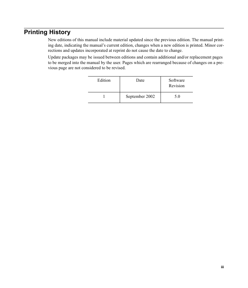
Printing History New editions of this manual include material updated since the previous edition. The manual print- ing date, indicating the manual’s current edition, changes when a new edition is printed. Minor cor- rections and updates incorporated at reprint do not cause the date to change. Update packages may be issued between editions and contain additional and/or replacement pages to be merged into the manual by the user. Pages which are rearranged because of changes on a pre- vious page are not considered to be revised. Edition Date Software Revision 1 September 2002 5.0 iii
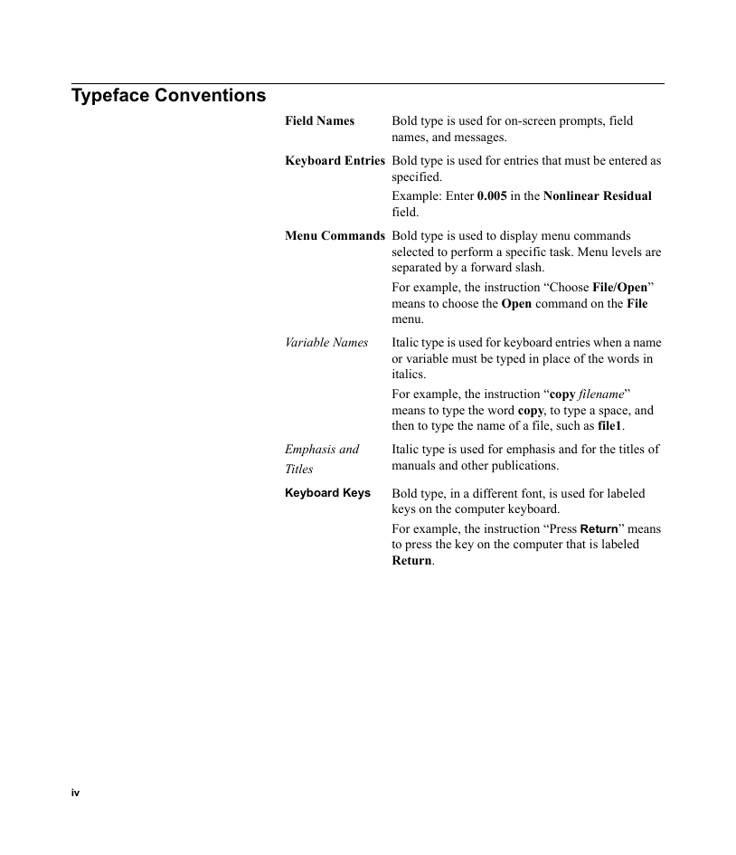
Typeface Conventions Field Names Bold type is used for on-screen prompts, field names, and messages. Keyboard Entries Bold type is used for entries that must be entered as specified. Example: Enter 0.005 in the Nonlinear Residual field. Menu Commands Bold type is used to display menu commands selected to perform a specific task. Menu levels are separated by a forward slash. For example, the instruction “Choose File/Open” means to choose the Open command on the File menu. Italic type is used for keyboard entries when a name or variable must be typed in place of the words in italics. For example, the instruction “copy filename” means to type the word copy, to type a space, and then to type the name of a file, such as file1. Italic type is used for emphasis and for the titles of manuals and other publications. Bold type, in a different font, is used for labeled keys on the computer keyboard. For example, the instruction “Press Return” means to press the key on the computer that is labeled Return. Variable Names Emphasis and Titles Keyboard Keys iv
Installation Before you use PExprt, you must: 1. Set up your system’s graphical windowing system. 2. If you have not yet done these steps, refer to the Ansoft installation guides and the documentation that came with your computer system, or ask your system administrator for help. Install the Ansoft software, using the directions in the Ansoft PC Installation Guide. v
Other References For more information on PExprt commands and features, refer to the PExprt online help. To start PExprt, you must first access the Maxwell Control Panel. For more detailed information on the Maxwell Control Panel commands, refer to the Maxwell Control Panel’s online help system. vi
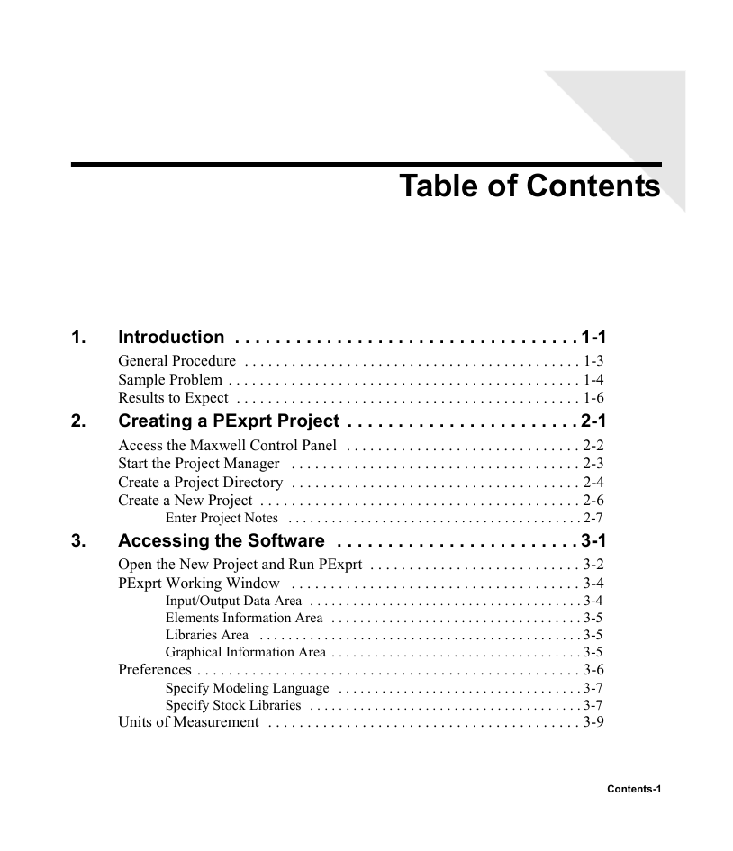
Table of Contents 1. 2. 3. Introduction . . . . . . . . . . . . . . . . . . . . . . . . . . . . . . . . . . 1-1 General Procedure . . . . . . . . . . . . . . . . . . . . . . . . . . . . . . . . . . . . . . . . . . . 1-3 Sample Problem . . . . . . . . . . . . . . . . . . . . . . . . . . . . . . . . . . . . . . . . . . . . . 1-4 Results to Expect . . . . . . . . . . . . . . . . . . . . . . . . . . . . . . . . . . . . . . . . . . . . 1-6 Creating a PExprt Project . . . . . . . . . . . . . . . . . . . . . . . 2-1 Access the Maxwell Control Panel . . . . . . . . . . . . . . . . . . . . . . . . . . . . . . 2-2 Start the Project Manager . . . . . . . . . . . . . . . . . . . . . . . . . . . . . . . . . . . . . 2-3 Create a Project Directory . . . . . . . . . . . . . . . . . . . . . . . . . . . . . . . . . . . . . 2-4 Create a New Project . . . . . . . . . . . . . . . . . . . . . . . . . . . . . . . . . . . . . . . . . 2-6 Enter Project Notes . . . . . . . . . . . . . . . . . . . . . . . . . . . . . . . . . . . . . . . . . 2-7 Accessing the Software . . . . . . . . . . . . . . . . . . . . . . . . 3-1 Open the New Project and Run PExprt . . . . . . . . . . . . . . . . . . . . . . . . . . . 3-2 PExprt Working Window . . . . . . . . . . . . . . . . . . . . . . . . . . . . . . . . . . . . . 3-4 Input/Output Data Area . . . . . . . . . . . . . . . . . . . . . . . . . . . . . . . . . . . . . . 3-4 Elements Information Area . . . . . . . . . . . . . . . . . . . . . . . . . . . . . . . . . . . 3-5 Libraries Area . . . . . . . . . . . . . . . . . . . . . . . . . . . . . . . . . . . . . . . . . . . . . 3-5 Graphical Information Area . . . . . . . . . . . . . . . . . . . . . . . . . . . . . . . . . . . 3-5 Preferences . . . . . . . . . . . . . . . . . . . . . . . . . . . . . . . . . . . . . . . . . . . . . . . . . 3-6 Specify Modeling Language . . . . . . . . . . . . . . . . . . . . . . . . . . . . . . . . . . 3-7 Specify Stock Libraries . . . . . . . . . . . . . . . . . . . . . . . . . . . . . . . . . . . . . . 3-7 Units of Measurement . . . . . . . . . . . . . . . . . . . . . . . . . . . . . . . . . . . . . . . . 3-9 Contents-1
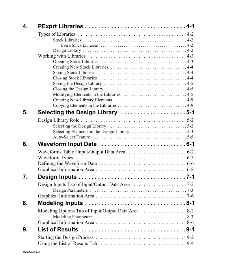
4. PExprt Libraries . . . . . . . . . . . . . . . . . . . . . . . . . . . . . . . 4-1 Types of Libraries . . . . . . . . . . . . . . . . . . . . . . . . . . . . . . . . . . . . . . . . . . . 4-2 Stock Libraries . . . . . . . . . . . . . . . . . . . . . . . . . . . . . . . . . . . . . . . . . . . . . 4-2 User's Stock Libraries . . . . . . . . . . . . . . . . . . . . . . . . . . . . . . . . . . . . . . . . . 4-2 Design Library . . . . . . . . . . . . . . . . . . . . . . . . . . . . . . . . . . . . . . . . . . . . . 4-2 Working with Libraries . . . . . . . . . . . . . . . . . . . . . . . . . . . . . . . . . . . . . . . 4-3 Opening Stock Libraries . . . . . . . . . . . . . . . . . . . . . . . . . . . . . . . . . . . . . 4-3 Creating New Stock Libraries . . . . . . . . . . . . . . . . . . . . . . . . . . . . . . . . . 4-4 Saving Stock Libraries . . . . . . . . . . . . . . . . . . . . . . . . . . . . . . . . . . . . . . . 4-4 Closing Stock Libraries . . . . . . . . . . . . . . . . . . . . . . . . . . . . . . . . . . . . . . 4-4 Saving the Design Library . . . . . . . . . . . . . . . . . . . . . . . . . . . . . . . . . . . . 4-5 Closing the Design Library . . . . . . . . . . . . . . . . . . . . . . . . . . . . . . . . . . . 4-5 Modifying Elements in the Libraries . . . . . . . . . . . . . . . . . . . . . . . . . . . . 4-5 Creating New Library Elements . . . . . . . . . . . . . . . . . . . . . . . . . . . . . . . 4-9 Copying Elements in the Libraries . . . . . . . . . . . . . . . . . . . . . . . . . . . . . . 4-9 Selecting the Design Library . . . . . . . . . . . . . . . . . . . . 5-1 Design Library Role . . . . . . . . . . . . . . . . . . . . . . . . . . . . . . . . . . . . . . . . . . 5-2 Selecting the Design Library . . . . . . . . . . . . . . . . . . . . . . . . . . . . . . . . . . 5-2 Selecting Elements in the Design Library . . . . . . . . . . . . . . . . . . . . . . . . 5-3 Auto-Select Feature . . . . . . . . . . . . . . . . . . . . . . . . . . . . . . . . . . . . . . . . . 5-5 6. Waveform Input Data . . . . . . . . . . . . . . . . . . . . . . . . . . 6-1 Waveforms Tab of Input/Output Data Area . . . . . . . . . . . . . . . . . . . . . . . 6-2 Waveform Types . . . . . . . . . . . . . . . . . . . . . . . . . . . . . . . . . . . . . . . . . . . . 6-3 Defining the Waveform Data . . . . . . . . . . . . . . . . . . . . . . . . . . . . . . . . . . . 6-6 Graphical Information Area . . . . . . . . . . . . . . . . . . . . . . . . . . . . . . . . . . . . 6-8 Design Inputs . . . . . . . . . . . . . . . . . . . . . . . . . . . . . . . . . 7-1 Design Inputs Tab of Input/Output Data Area . . . . . . . . . . . . . . . . . . . . . . 7-2 Design Parameters . . . . . . . . . . . . . . . . . . . . . . . . . . . . . . . . . . . . . . . . . . 7-3 Graphical Information Area . . . . . . . . . . . . . . . . . . . . . . . . . . . . . . . . . . . . 7-6 Modeling Inputs . . . . . . . . . . . . . . . . . . . . . . . . . . . . . . . 8-1 Modeling Options Tab of Input/Output Data Area . . . . . . . . . . . . . . . . . . 8-2 Modeling Parameters . . . . . . . . . . . . . . . . . . . . . . . . . . . . . . . . . . . . . . . . 8-3 Graphical Information Area . . . . . . . . . . . . . . . . . . . . . . . . . . . . . . . . . . . . 8-6 List of Results . . . . . . . . . . . . . . . . . . . . . . . . . . . . . . . . 9-1 Starting the Design Process . . . . . . . . . . . . . . . . . . . . . . . . . . . . . . . . . . . . 9-2 Using the List of Results Tab . . . . . . . . . . . . . . . . . . . . . . . . . . . . . . . . . . 9-4 9. 5. 7. 8. Contents-2
分享到:
收藏