logo资料库

OSEK-VDX COM.pdf

第1页 / 共71页
第2页 / 共71页
第3页 / 共71页
第4页 / 共71页
第5页 / 共71页
第6页 / 共71页
第7页 / 共71页
第8页 / 共71页
资料共71页,剩余部分请下载后查看
Introduction
Requirements
Communication concept
Structure of this document
Interaction Layer
Overview
Introduction
Communication concept
Configuration
Message reception
Message reception overview
Reception filtering
Copying message data into message objects data area
Copying data to application messages
Unqueued and queued messages
Queued message
Unqueued message
Message transmission
Message transmission overview
Transfer of internal messages
Transfer properties for external communication
Triggered Transfer Property
Pending Transfer Property
Transmission modes
Direct Transmission Mode
Periodic Transmission Mode
Mixed Transmission Mode
Activation / Deactivation of periodic transmission mechanism
Message filtering algorithm
Byte ordering
Deadline monitoring
Reception Deadline Monitoring
Transmission Deadline Monitoring
Direct Transmission Mode
Periodic Transmission Mode
Mixed Transmission Mode
Notification
Notification classes
Notification mechanisms
Interface for callback routines
Communication system management
Initialisation / Shutdown
Error handling
General remarks
Error hook routine
Error management
Functional model of the Interaction Layer
Interfaces
Interface to OSEK Indirect NM
I-PDU transfer indication
I-PDU time-out indication
Application Program Interface (API)
Service parameter types
StatusType
SymbolicName
ApplicationDataRef
LengthRef
FlagValue
COMApplicationModeType
COMShutdownModeType
CalloutReturnType
COMServiceIdType
Start-up services
StartCOM
StopCOM
GetCOMApplicationMode
InitMessage
StartPeriodic
StopPeriodic
Notification mechanism support services
ReadFlag
ResetFlag
Communication services
SendMessage
ReceiveMessage
SendDynamicMessage
ReceiveDynamicMessage
SendZeroMessage
GetMessageStatus
COMErrorGetServiceId
Routines provided by the application
StartCOMExtension
Callouts
COMErrorHook
COMError_Name1_Name2 macros
Minimum requirements of lower communication layers
Conformance Classes
Open Systems and the Corresponding Interfaces for Automotive Electronics OSEK/VDX Communication Version 3.0.1 January 29, 2003 This document is an official release and replaces all previously distributed documents. The OSEK group retains the right to make changes to this document without notice and does not accept liability for errors. All rights reserved. No part of this document may be reproduced, in any form or by any means, without permission in writing from the OSEK/VDX steering committee. OSEK/VDX COM 3.0.1  by OSEK - 1 -
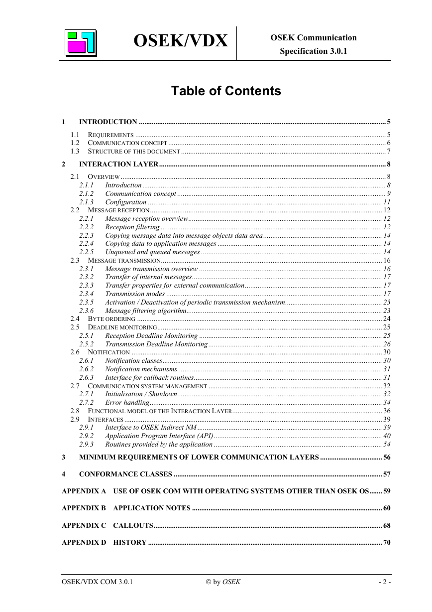
OSEK/VDX OSEK Communication Specification 3.0.1 Table of Contents 1 2 2.1.1 2.1.2 2.1.3 INTRODUCTION ....................................................................................................................................... 5 1.1 REQUIREMENTS ......................................................................................................................................... 5 1.2 COMMUNICATION CONCEPT....................................................................................................................... 6 1.3 STRUCTURE OF THIS DOCUMENT ................................................................................................................ 7 INTERACTION LAYER............................................................................................................................ 8 2.1 OVERVIEW................................................................................................................................................. 8 Introduction ..................................................................................................................................... 8 Communication concept .................................................................................................................. 9 Configuration ................................................................................................................................ 11 2.2 MESSAGE RECEPTION............................................................................................................................... 12 2.2.1 Message reception overview.......................................................................................................... 12 Reception filtering ......................................................................................................................... 12 2.2.2 2.2.3 Copying message data into message objects data area................................................................. 14 2.2.4 Copying data to application messages .......................................................................................... 14 2.2.5 Unqueued and queued messages ................................................................................................... 14 2.3 MESSAGE TRANSMISSION......................................................................................................................... 16 2.3.1 Message transmission overview .................................................................................................... 16 2.3.2 Transfer of internal messages........................................................................................................ 17 Transfer properties for external communication........................................................................... 17 2.3.3 Transmission modes ...................................................................................................................... 17 2.3.4 2.3.5 Activation / Deactivation of periodic transmission mechanism..................................................... 23 2.3.6 Message filtering algorithm........................................................................................................... 23 2.4 BYTE ORDERING ...................................................................................................................................... 24 2.5 DEADLINE MONITORING........................................................................................................................... 25 Reception Deadline Monitoring .................................................................................................... 25 Transmission Deadline Monitoring............................................................................................... 26 2.6 NOTIFICATION ......................................................................................................................................... 30 Notification classes........................................................................................................................ 30 Notification mechanisms................................................................................................................ 31 Interface for callback routines....................................................................................................... 31 2.7 COMMUNICATION SYSTEM MANAGEMENT ............................................................................................... 32 Initialisation / Shutdown................................................................................................................ 32 Error handling............................................................................................................................... 34 2.8 FUNCTIONAL MODEL OF THE INTERACTION LAYER.................................................................................. 36 2.9 INTERFACES............................................................................................................................................. 39 Interface to OSEK Indirect NM ..................................................................................................... 39 Application Program Interface (API)............................................................................................ 40 Routines provided by the application ............................................................................................ 54 3 MINIMUM REQUIREMENTS OF LOWER COMMUNICATION LAYERS .................................. 56 2.9.1 2.9.2 2.9.3 2.5.1 2.5.2 2.6.1 2.6.2 2.6.3 2.7.1 2.7.2 4 CONFORMANCE CLASSES .................................................................................................................. 57 APPENDIX A USE OF OSEK COM WITH OPERATING SYSTEMS OTHER THAN OSEK OS....... 59 APPENDIX B APPLICATION NOTES ........................................................................................................ 60 APPENDIX C CALLOUTS............................................................................................................................. 68 APPENDIX D HISTORY ................................................................................................................................ 70 OSEK/VDX COM 3.0.1  by OSEK - 2 -
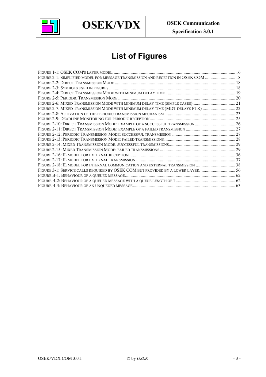
OSEK/VDX OSEK Communication Specification 3.0.1 List of Figures FIGURE 1-1: OSEK COM'S LAYER MODEL............................................................................................................... 6 FIGURE 2-1: SIMPLIFIED MODEL FOR MESSAGE TRANSMISSION AND RECEPTION IN OSEK COM............................. 8 FIGURE 2-2: DIRECT TRANSMISSION MODE ........................................................................................................... 18 FIGURE 2-3: SYMBOLS USED IN FIGURES ................................................................................................................ 18 FIGURE 2-4: DIRECT TRANSMISSION MODE WITH MINIMUM DELAY TIME .............................................................. 19 FIGURE 2-5: PERIODIC TRANSMISSION MODE ........................................................................................................ 20 FIGURE 2-6: MIXED TRANSMISSION MODE WITH MINIMUM DELAY TIME (SIMPLE CASES)...................................... 21 FIGURE 2-7: MIXED TRANSMISSION MODE WITH MINIMUM DELAY TIME (MDT DELAYS PTR) ............................. 22 FIGURE 2-8: ACTIVATION OF THE PERIODIC TRANSMISSION MECHANISM ............................................................... 23 FIGURE 2-9: DEADLINE MONITORING FOR PERIODIC RECEPTION............................................................................ 25 FIGURE 2-10: DIRECT TRANSMISSION MODE: EXAMPLE OF A SUCCESSFUL TRANSMISSION.................................... 26 FIGURE 2-11: DIRECT TRANSMISSION MODE: EXAMPLE OF A FAILED TRANSMISSION ............................................ 27 FIGURE 2-12: PERIODIC TRANSMISSION MODE: SUCCESSFUL TRANSMISSION ........................................................ 27 FIGURE 2-13: PERIODIC TRANSMISSION MODE: FAILED TRANSMISSIONS ............................................................... 28 FIGURE 2-14: MIXED TRANSMISSION MODE: SUCCESSFUL TRANSMISSIONS........................................................... 29 FIGURE 2-15: MIXED TRANSMISSION MODE: FAILED TRANSMISSIONS................................................................... 29 FIGURE 2-16: IL MODEL FOR EXTERNAL RECEPTION .............................................................................................. 36 FIGURE 2-17: IL MODEL FOR EXTERNAL TRANSMISSION ........................................................................................ 37 FIGURE 2-18: IL MODEL FOR INTERNAL COMMUNICATION AND EXTERNAL TRANSMISSION ................................... 38 FIGURE 3-1: SERVICE CALLS REQUIRED BY OSEK COM BUT PROVIDED BY A LOWER LAYER................................ 56 FIGURE B-1: BEHAVIOUR OF A QUEUED MESSAGE.................................................................................................. 62 FIGURE B-2: BEHAVIOUR OF A QUEUED MESSAGE WITH A QUEUE LENGTH OF 1..................................................... 62 FIGURE B-3: BEHAVIOUR OF AN UNQUEUED MESSAGE........................................................................................... 63 OSEK/VDX COM 3.0.1  by OSEK - 3 -
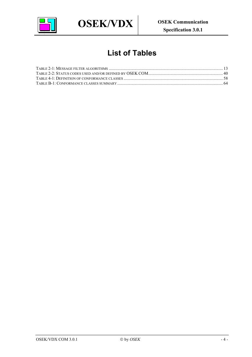
OSEK/VDX OSEK Communication Specification 3.0.1 List of Tables TABLE 2-1: MESSAGE FILTER ALGORITHMS ........................................................................................................... 13 TABLE 2-2: STATUS CODES USED AND/OR DEFINED BY OSEK COM...................................................................... 40 TABLE 4-1: DEFINITION OF CONFORMANCE CLASSES ............................................................................................. 58 TABLE B-1: CONFORMANCE CLASSES SUMMARY................................................................................................... 64 OSEK/VDX COM 3.0.1  by OSEK - 4 -
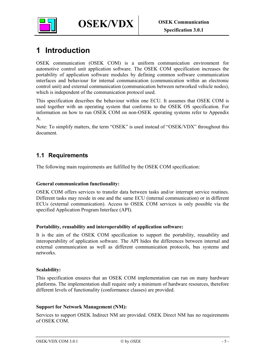
OSEK/VDX OSEK Communication Specification 3.0.1 1 Introduction OSEK communication (OSEK COM) is a uniform communication environment for automotive control unit application software. The OSEK COM specification increases the portability of application software modules by defining common software communication interfaces and behaviour for internal communication (communication within an electronic control unit) and external communication (communication between networked vehicle nodes), which is independent of the communication protocol used. This specification describes the behaviour within one ECU. It assumes that OSEK COM is used together with an operating system that conforms to the OSEK OS specification. For information on how to run OSEK COM on non-OSEK operating systems refer to Appendix A. Note: To simplify matters, the term “OSEK” is used instead of “OSEK/VDX” throughout this document. 1.1 Requirements The following main requirements are fulfilled by the OSEK COM specification: General communication functionality: OSEK COM offers services to transfer data between tasks and/or interrupt service routines. Different tasks may reside in one and the same ECU (internal communication) or in different ECUs (external communication). Access to OSEK COM services is only possible via the specified Application Program Interface (API). Portability, reusability and interoperability of application software: It is the aim of the OSEK COM specification to support the portability, reusability and interoperability of application software. The API hides the differences between internal and external communication as well as different communication protocols, bus systems and networks. Scalability: This specification ensures that an OSEK COM implementation can run on many hardware platforms. The implementation shall require only a minimum of hardware resources, therefore different levels of functionality (conformance classes) are provided. Support for Network Management (NM): Services to support OSEK Indirect NM are provided. OSEK Direct NM has no requirements of OSEK COM. OSEK/VDX COM 3.0.1  by OSEK - 5 -
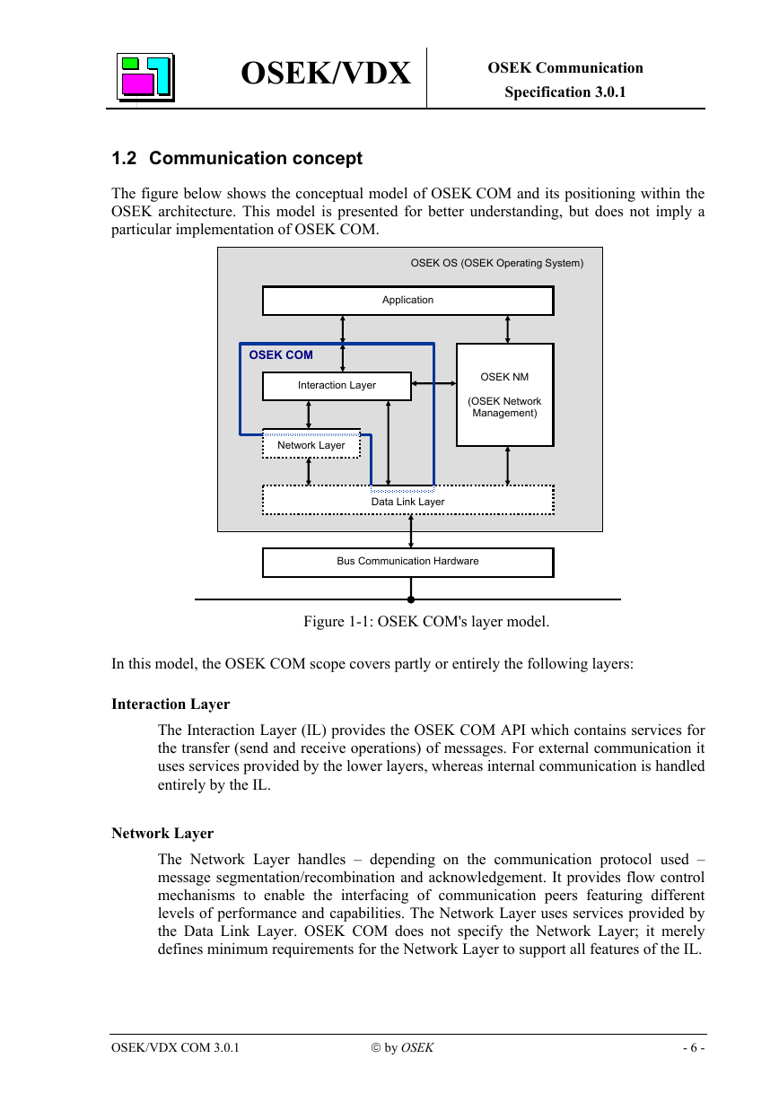
OSEK/VDX OSEK Communication Specification 3.0.1 1.2 Communication concept The figure below shows the conceptual model of OSEK COM and its positioning within the OSEK architecture. This model is presented for better understanding, but does not imply a particular implementation of OSEK COM. OSEK OS (OSEK Operating System) Application OSEK COM Interaction Layer Network Layer OSEK NM (OSEK Network Management) Data Link Layer Bus Communication Hardware Figure 1-1: OSEK COM's layer model. In this model, the OSEK COM scope covers partly or entirely the following layers: Interaction Layer The Interaction Layer (IL) provides the OSEK COM API which contains services for the transfer (send and receive operations) of messages. For external communication it uses services provided by the lower layers, whereas internal communication is handled entirely by the IL. Network Layer The Network Layer handles – depending on the communication protocol used – message segmentation/recombination and acknowledgement. It provides flow control mechanisms to enable the interfacing of communication peers featuring different levels of performance and capabilities. The Network Layer uses services provided by the Data Link Layer. OSEK COM does not specify the Network Layer; it merely defines minimum requirements for the Network Layer to support all features of the IL. OSEK/VDX COM 3.0.1  by OSEK - 6 -
OSEK/VDX OSEK Communication Specification 3.0.1 Data Link Layer The Data Link Layer provides the upper layers with services for the unacknowledged transfer of individual data packets (frames) over a network. Additionally, it provides services for the NM. OSEK COM does not specify the Data Link Layer; it merely defines minimum requirements for the Data Link Layer to support all features of the IL. 1.3 Structure of this document In the following text, the specification chapters are described briefly. Chapters 1 to 4 are normative, the appendices are descriptive. Chapter 1: Introduction This chapter describes the motivation and requirements for OSEK COM, the conceptual model used and the structure of the document. Chapter 2: Interaction Layer This chapter describes the functionality of the IL of the OSEK COM model and defines its API. Chapter 3: Minimum requirements of lower communication layers This chapter lists the requirements imposed by OSEK COM on the lower communication layers (Network Layer and Data Link Layer) to support all features of the IL. Chapter 4: Conformance Classes This chapter specifies the Communication Conformance Classes, which allow the adaptation of the feature content of OSEK COM implementations to the target system's requirements. Appendix A: Use of OSEK COM with operating systems other than OSEK OS This appendix gives hints on how to run OSEK COM on non-OSEK operating systems. Appendix B: Application notes This appendix provides information on how to meet specific application requirements with the given OSEK COM model. Appendix C: Callouts This appendix supplies application examples for callouts. Appendix D: History This appendix lists all official releases of the OSEK COM specification and the relevant changes between them. OSEK/VDX COM 3.0.1  by OSEK - 7 -
OSEK Communication Specification 3.0.1 OSEK/VDX 2 Interaction Layer 2.1 Overview 2.1.1 Introduction The communication in OSEK COM is based on messages1. A message contains application- specific data. Messages and message properties are configured statically via the OSEK Implementation Language (OIL). The content and usage of messages is not relevant to OSEK COM. Messages with a length of zero (zero-length messages, see Appendix B) are allowed. In the case of internal communication the Interaction Layer (IL) makes the message data immediately available to the receiver (see Figure 2-1). In the case of external communication the IL packs one or more messages into assigned Interaction Layer Protocol Data Units (I- PDU) and passes them to the underlying layer (see Figure 2-1). The functionality of internal communication is a sub-set of the functionality of external communication. Internal-external communication occurs when the same message is sent internally as well as externally. Administration of messages is done in the IL based on message objects. Message objects exist on the sending side (sending message object) and on the receiving side (receiving message object). SendMessage ReceiveMessage Application Application Message Message Object Internal Communication Message Transfer Message Extraction internal & external Interaction external Layer I-PDU I-PDU Transmission Transmission Request Underlying Layer PDU I-PDU Reception Reception Indication Underlying Layer Figure 2-1: Simplified model for message transmission and reception in OSEK COM (see section 2.8 for a detailed description) ______________________________ 1 The concept of messages has changed from previous versions of this specification. Messages are often called signals. Thus, OSEK COM offers a signal-based interface. OSEK/VDX COM 3.0.1  by OSEK - 8 -
分享到:
收藏