logo资料库

电脑CPU电路图.pdf

第1页 / 共96页
第2页 / 共96页
第3页 / 共96页
第4页 / 共96页
第5页 / 共96页
第6页 / 共96页
第7页 / 共96页
第8页 / 共96页
资料共96页,剩余部分请下载后查看
Contents
List of Figures
List of Tables
Revision History
1 Overview
1.1 QuantiSpeed™ Architecture Summary
2 Interface Signals
2.1 Overview
2.2 Signaling Technology
2.3 Push-Pull (PP) Drivers
2.4 AMDAthlon™ System Bus Signals
3 Logic Symbol Diagram
4 Power Management
4.1 Power Management States
Working State
Halt State
Stop Grant States
Probe State
4.2 Connect and Disconnect Protocol
Connect Protocol
Connect State Diagram
4.3 Clock Control
5 CPUID Support
6 Thermal Design
7 Electrical Data
7.1 Conventions
7.2 Interface Signal Groupings
7.3 Voltage Identification (VID[4:0])
7.4 Frequency Identification (FID[3:0])
7.5 VCCA AC and DC Characteristics
7.6 Decoupling
7.7 VCC_CORE Characteristics
7.8 Absolute Ratings
7.9 VCC_CORE Voltage and Current
7.10 SYSCLK and SYSCLK# AC and DC Characteristics
7.11 AMD Athlon™ System Bus AC and DC Characteristics
7.12 General AC and DC Characteristics
7.13 Open-Drain Test Circuit
7.14 Thermal Diode Characteristics
Thermal Diode Electrical Characteristics
Thermal Protection Characterization
7.15 APIC Pins AC and DC Characteristics
8 Signal and Power-Up Requirements
8.1 Power-Up Requirements
Signal Sequence and Timing Description
Clock Multiplier Selection (FID[3:0])
8.2 Processor Warm Reset Requirements
Northbridge Reset Pins
9 Mechanical Data
9.1 Introduction
9.2 Die Loading
9.3 OPGA Package Dimensions
10 Pin Descriptions
10.1 Pin Diagram and Pin Name Abbreviations
10.2 Pin List
10.3 Detailed Pin Descriptions
A20M# Pin
AMD Pin
AMD Athlon™ System Bus Pins
Analog Pin
APIC Pins, PICCLK, PICD[1:0]#
CLKFWDRST Pin
CLKIN, RSTCLK (SYSCLK) Pins
CONNECT Pin
COREFB and COREFB# Pins
CPU_PRESENCE# Pin
DBRDY and DBREQ# Pins
FERR Pin
FID[3:0] Pins
FLUSH# Pin
IGNNE# Pin
INIT# Pin
INTR Pin
JTAG Pins
K7CLKOUT and K7CLKOUT# Pins
Key Pins
NC Pins
NMI Pin
PGA Orientation Pins
PLL Bypass and Test Pins
PWROK Pin
SADDIN[1:0]# and SADDOUT[1:0]# Pins
Scan Pins
SMI# Pin
STPCLK# Pin
SYSCLK and SYSCLK#
THERMDA and THERMDC Pins
VCCA Pin
VID[4:0] Pins
VREFSYS Pin
ZN and ZP Pins
11 Ordering Information
Standard AMD Athlon™ XP Processor Model 8 Products
Thermal Diode Calculations
Ideal Diode Equation
Temperature Offset Correction
Conventions and Abbreviations
Signals and Bits
Data Terminology
Abbreviations and Acronyms
Preliminary Information AMD Athlon XP Processor Model 8 TM Data Sheet Publication # 25175 Rev. B Issue Date: June 2002
Preliminary Information © 2002 Advanced Micro Devices, Inc. All rights reserved. The contents of this document are provided in connection with Advanced Micro Devices, Inc. (“AMD”) products. AMD makes no representations or war- ranties with respect to the accuracy or completeness of the contents of this publication and reserves the right to make changes to specifications and prod- uct descriptions at any time without notice. No license, whether express, implied, arising by estoppel or otherwise, to any intellectual property rights is granted by this publication. Except as set forth in AMD’s Standard Terms and Conditions of Sale, AMD assumes no liability whatsoever, and disclaims any express or implied warranty, relating to its products including, but not limited to, the implied warranty of merchantability, fitness for a particular purpose, or infringement of any intellectual property right. AMD’s products are not designed, intended, authorized or warranted for use as components in systems intended for surgical implant into the body, or in other applications intended to support or sustain life, or in any other applica- tion in which the failure of AMD’s product could create a situation where per- sonal injury, death, or severe property or environmental damage may occur. AMD reserves the right to discontinue or make changes to its products at any time without notice. Trademarks AMD, the AMD Arrow logo, AMD Athlon, AMD Duron, and combinations thereof, QuantiSpeed, and 3DNow! are trademarks of Advanced Micro Devices, Inc. HyperTransport is a trademark of the HyperTransport Technology Consortium. MMX is a trademark of Intel Corporation. Windows is a registered trademark of Microsoft Corporation. Other product names used in this publication are for identification purposes only and may be trademarks of their respective companies.
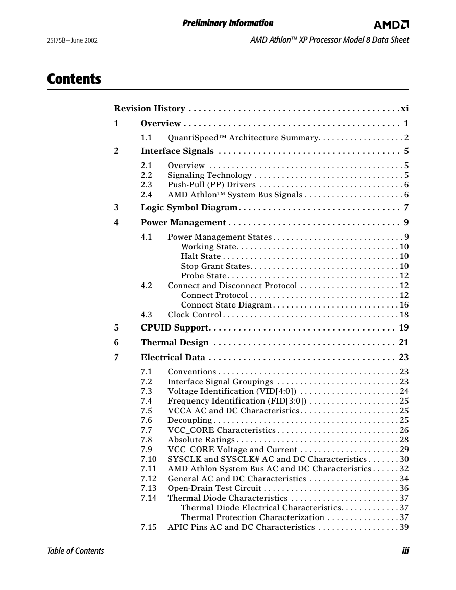
Preliminary Information AMD Athlon™ XP Processor Model 8 Data Sheet 25175B—June 2002 Contents 2 3 4 4.2 Revision History . . . . . . . . . . . . . . . . . . . . . . . . . . . . . . . . . . . . . . . . . . . xi 1 Overview . . . . . . . . . . . . . . . . . . . . . . . . . . . . . . . . . . . . . . . . . . . . 1 1.1 QuantiSpeed™ Architecture Summary. . . . . . . . . . . . . . . . . . . 2 Interface Signals . . . . . . . . . . . . . . . . . . . . . . . . . . . . . . . . . . . . . 5 Overview . . . . . . . . . . . . . . . . . . . . . . . . . . . . . . . . . . . . . . . . . . . 5 2.1 2.2 Signaling Technology . . . . . . . . . . . . . . . . . . . . . . . . . . . . . . . . . 5 Push-Pull (PP) Drivers . . . . . . . . . . . . . . . . . . . . . . . . . . . . . . . . 6 2.3 2.4 AMD Athlon™ System Bus Signals . . . . . . . . . . . . . . . . . . . . . . 6 Logic Symbol Diagram. . . . . . . . . . . . . . . . . . . . . . . . . . . . . . . . . 7 Power Management . . . . . . . . . . . . . . . . . . . . . . . . . . . . . . . . . . . 9 Power Management States . . . . . . . . . . . . . . . . . . . . . . . . . . . . . 9 4.1 Working State. . . . . . . . . . . . . . . . . . . . . . . . . . . . . . . . . . . . 10 Halt State . . . . . . . . . . . . . . . . . . . . . . . . . . . . . . . . . . . . . . . 10 Stop Grant States. . . . . . . . . . . . . . . . . . . . . . . . . . . . . . . . . 10 Probe State. . . . . . . . . . . . . . . . . . . . . . . . . . . . . . . . . . . . . . 12 Connect and Disconnect Protocol . . . . . . . . . . . . . . . . . . . . . . 12 Connect Protocol . . . . . . . . . . . . . . . . . . . . . . . . . . . . . . . . . 12 Connect State Diagram . . . . . . . . . . . . . . . . . . . . . . . . . . . . 16 Clock Control . . . . . . . . . . . . . . . . . . . . . . . . . . . . . . . . . . . . . . . 18 4.3 CPUID Support. . . . . . . . . . . . . . . . . . . . . . . . . . . . . . . . . . . . . . 19 Thermal Design . . . . . . . . . . . . . . . . . . . . . . . . . . . . . . . . . . . . . 21 Electrical Data . . . . . . . . . . . . . . . . . . . . . . . . . . . . . . . . . . . . . . 23 Conventions . . . . . . . . . . . . . . . . . . . . . . . . . . . . . . . . . . . . . . . . 23 7.1 Interface Signal Groupings . . . . . . . . . . . . . . . . . . . . . . . . . . . 23 7.2 7.3 Voltage Identification (VID[4:0]) . . . . . . . . . . . . . . . . . . . . . . 24 Frequency Identification (FID[3:0]) . . . . . . . . . . . . . . . . . . . . 25 7.4 VCCA AC and DC Characteristics . . . . . . . . . . . . . . . . . . . . . . 25 7.5 Decoupling . . . . . . . . . . . . . . . . . . . . . . . . . . . . . . . . . . . . . . . . . 25 7.6 7.7 VCC_CORE Characteristics . . . . . . . . . . . . . . . . . . . . . . . . . . . 26 Absolute Ratings . . . . . . . . . . . . . . . . . . . . . . . . . . . . . . . . . . . . 28 7.8 VCC_CORE Voltage and Current . . . . . . . . . . . . . . . . . . . . . . 29 7.9 7.10 SYSCLK and SYSCLK# AC and DC Characteristics . . . . . . . 30 7.11 AMD Athlon System Bus AC and DC Characteristics . . . . . . 32 7.12 General AC and DC Characteristics . . . . . . . . . . . . . . . . . . . . 34 7.13 Open-Drain Test Circuit . . . . . . . . . . . . . . . . . . . . . . . . . . . . . . 36 Thermal Diode Characteristics . . . . . . . . . . . . . . . . . . . . . . . . 37 7.14 Thermal Diode Electrical Characteristics. . . . . . . . . . . . . 37 Thermal Protection Characterization . . . . . . . . . . . . . . . . 37 7.15 APIC Pins AC and DC Characteristics . . . . . . . . . . . . . . . . . . 39 5 6 7 Table of Contents iii
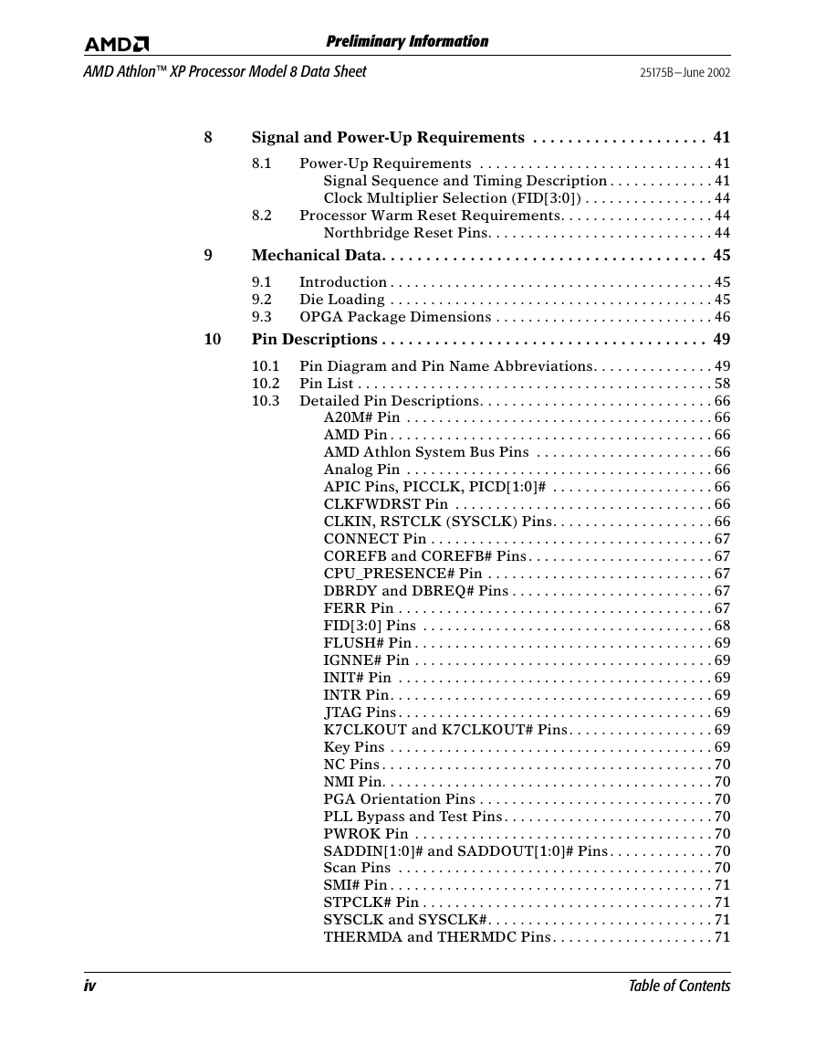
AMD Athlon™ XP Processor Model 8 Data Sheet 25175B—June 2002 Preliminary Information 8 9 10 8.2 Signal and Power-Up Requirements . . . . . . . . . . . . . . . . . . . . 41 Power-Up Requirements . . . . . . . . . . . . . . . . . . . . . . . . . . . . . 41 8.1 Signal Sequence and Timing Description . . . . . . . . . . . . . 41 Clock Multiplier Selection (FID[3:0]) . . . . . . . . . . . . . . . . 44 Processor Warm Reset Requirements. . . . . . . . . . . . . . . . . . . 44 Northbridge Reset Pins. . . . . . . . . . . . . . . . . . . . . . . . . . . . 44 Mechanical Data. . . . . . . . . . . . . . . . . . . . . . . . . . . . . . . . . . . . . 45 Introduction . . . . . . . . . . . . . . . . . . . . . . . . . . . . . . . . . . . . . . . . 45 9.1 9.2 Die Loading . . . . . . . . . . . . . . . . . . . . . . . . . . . . . . . . . . . . . . . . 45 9.3 OPGA Package Dimensions . . . . . . . . . . . . . . . . . . . . . . . . . . . 46 Pin Descriptions . . . . . . . . . . . . . . . . . . . . . . . . . . . . . . . . . . . . . 49 Pin Diagram and Pin Name Abbreviations. . . . . . . . . . . . . . . 49 10.1 10.2 Pin List . . . . . . . . . . . . . . . . . . . . . . . . . . . . . . . . . . . . . . . . . . . . 58 10.3 Detailed Pin Descriptions. . . . . . . . . . . . . . . . . . . . . . . . . . . . . 66 A20M# Pin . . . . . . . . . . . . . . . . . . . . . . . . . . . . . . . . . . . . . . 66 AMD Pin . . . . . . . . . . . . . . . . . . . . . . . . . . . . . . . . . . . . . . . . 66 AMD Athlon System Bus Pins . . . . . . . . . . . . . . . . . . . . . . 66 Analog Pin . . . . . . . . . . . . . . . . . . . . . . . . . . . . . . . . . . . . . . 66 APIC Pins, PICCLK, PICD[1:0]# . . . . . . . . . . . . . . . . . . . . 66 CLKFWDRST Pin . . . . . . . . . . . . . . . . . . . . . . . . . . . . . . . . 66 CLKIN, RSTCLK (SYSCLK) Pins. . . . . . . . . . . . . . . . . . . . 66 CONNECT Pin . . . . . . . . . . . . . . . . . . . . . . . . . . . . . . . . . . . 67 COREFB and COREFB# Pins . . . . . . . . . . . . . . . . . . . . . . . 67 CPU_PRESENCE# Pin . . . . . . . . . . . . . . . . . . . . . . . . . . . . 67 DBRDY and DBREQ# Pins . . . . . . . . . . . . . . . . . . . . . . . . . 67 FERR Pin . . . . . . . . . . . . . . . . . . . . . . . . . . . . . . . . . . . . . . . 67 FID[3:0] Pins . . . . . . . . . . . . . . . . . . . . . . . . . . . . . . . . . . . . 68 FLUSH# Pin . . . . . . . . . . . . . . . . . . . . . . . . . . . . . . . . . . . . . 69 IGNNE# Pin . . . . . . . . . . . . . . . . . . . . . . . . . . . . . . . . . . . . . 69 INIT# Pin . . . . . . . . . . . . . . . . . . . . . . . . . . . . . . . . . . . . . . . 69 INTR Pin. . . . . . . . . . . . . . . . . . . . . . . . . . . . . . . . . . . . . . . . 69 JTAG Pins . . . . . . . . . . . . . . . . . . . . . . . . . . . . . . . . . . . . . . . 69 K7CLKOUT and K7CLKOUT# Pins . . . . . . . . . . . . . . . . . . 69 Key Pins . . . . . . . . . . . . . . . . . . . . . . . . . . . . . . . . . . . . . . . . 69 NC Pins . . . . . . . . . . . . . . . . . . . . . . . . . . . . . . . . . . . . . . . . . 70 NMI Pin. . . . . . . . . . . . . . . . . . . . . . . . . . . . . . . . . . . . . . . . . 70 PGA Orientation Pins . . . . . . . . . . . . . . . . . . . . . . . . . . . . . 70 PLL Bypass and Test Pins . . . . . . . . . . . . . . . . . . . . . . . . . . 70 PWROK Pin . . . . . . . . . . . . . . . . . . . . . . . . . . . . . . . . . . . . . 70 SADDIN[1:0]# and SADDOUT[1:0]# Pins . . . . . . . . . . . . . 70 Scan Pins . . . . . . . . . . . . . . . . . . . . . . . . . . . . . . . . . . . . . . . 70 SMI# Pin . . . . . . . . . . . . . . . . . . . . . . . . . . . . . . . . . . . . . . . . 71 STPCLK# Pin . . . . . . . . . . . . . . . . . . . . . . . . . . . . . . . . . . . . 71 SYSCLK and SYSCLK#. . . . . . . . . . . . . . . . . . . . . . . . . . . . 71 THERMDA and THERMDC Pins . . . . . . . . . . . . . . . . . . . . 71 iv Table of Contents
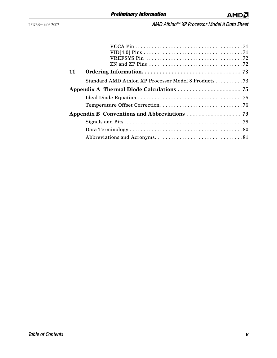
25175B—June 2002 AMD Athlon™ XP Processor Model 8 Data Sheet Preliminary Information 11 VCCA Pin . . . . . . . . . . . . . . . . . . . . . . . . . . . . . . . . . . . . . . . 71 VID[4:0] Pins . . . . . . . . . . . . . . . . . . . . . . . . . . . . . . . . . . . . 71 VREFSYS Pin . . . . . . . . . . . . . . . . . . . . . . . . . . . . . . . . . . . 72 ZN and ZP Pins . . . . . . . . . . . . . . . . . . . . . . . . . . . . . . . . . . 72 Ordering Information. . . . . . . . . . . . . . . . . . . . . . . . . . . . . . . . . 73 Standard AMD Athlon XP Processor Model 8 Products . . . . . . . . . . 73 Appendix A Thermal Diode Calculations . . . . . . . . . . . . . . . . . . . . . 75 Ideal Diode Equation . . . . . . . . . . . . . . . . . . . . . . . . . . . . . . . . . . . . . . 75 Temperature Offset Correction . . . . . . . . . . . . . . . . . . . . . . . . . . . . . . 76 Appendix B Conventions and Abbreviations . . . . . . . . . . . . . . . . . . 79 Signals and Bits . . . . . . . . . . . . . . . . . . . . . . . . . . . . . . . . . . . . . . . . . . . 79 Data Terminology . . . . . . . . . . . . . . . . . . . . . . . . . . . . . . . . . . . . . . . . . 80 Abbreviations and Acronyms. . . . . . . . . . . . . . . . . . . . . . . . . . . . . . . . 81 Table of Contents v
AMD Athlon™ XP Processor Model 8 Data Sheet 25175B—June 2002 Preliminary Information vi Table of Contents
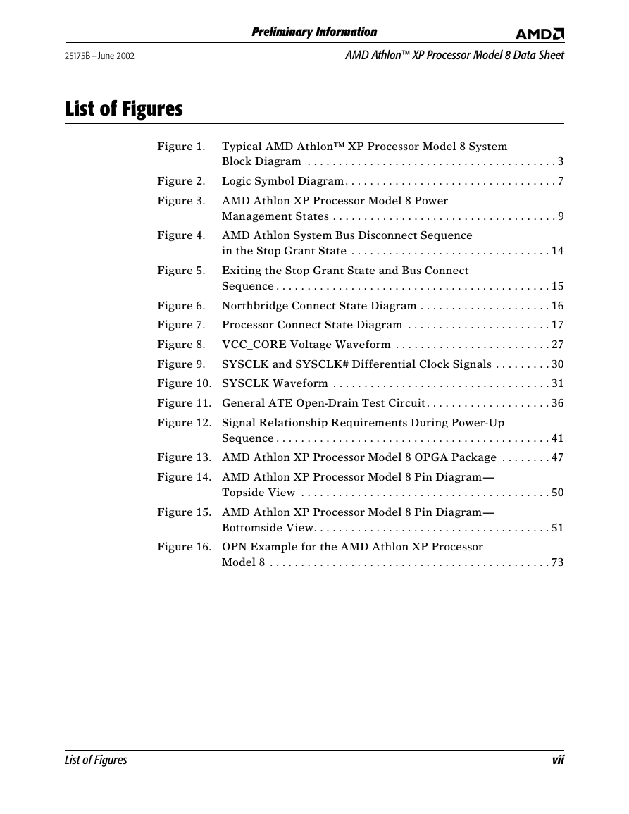
25175B—June 2002 AMD Athlon™ XP Processor Model 8 Data Sheet Preliminary Information List of Figures Figure 1. Typical AMD Athlon™ XP Processor Model 8 System Block Diagram . . . . . . . . . . . . . . . . . . . . . . . . . . . . . . . . . . . . . . . . 3 Figure 2. Logic Symbol Diagram. . . . . . . . . . . . . . . . . . . . . . . . . . . . . . . . . . 7 Figure 3. AMD Athlon XP Processor Model 8 Power Management States . . . . . . . . . . . . . . . . . . . . . . . . . . . . . . . . . . . . 9 Figure 4. AMD Athlon System Bus Disconnect Sequence in the Stop Grant State . . . . . . . . . . . . . . . . . . . . . . . . . . . . . . . . 14 Figure 5. Exiting the Stop Grant State and Bus Connect Sequence . . . . . . . . . . . . . . . . . . . . . . . . . . . . . . . . . . . . . . . . . . . . 15 Figure 6. Northbridge Connect State Diagram . . . . . . . . . . . . . . . . . . . . . 16 Figure 7. Processor Connect State Diagram . . . . . . . . . . . . . . . . . . . . . . . 17 Figure 8. VCC_CORE Voltage Waveform . . . . . . . . . . . . . . . . . . . . . . . . . 27 Figure 9. SYSCLK and SYSCLK# Differential Clock Signals . . . . . . . . . 30 Figure 10. SYSCLK Waveform . . . . . . . . . . . . . . . . . . . . . . . . . . . . . . . . . . . 31 Figure 11. General ATE Open-Drain Test Circuit. . . . . . . . . . . . . . . . . . . . 36 Figure 12. Signal Relationship Requirements During Power-Up Sequence . . . . . . . . . . . . . . . . . . . . . . . . . . . . . . . . . . . . . . . . . . . . 41 Figure 13. AMD Athlon XP Processor Model 8 OPGA Package . . . . . . . . 47 Figure 14. AMD Athlon XP Processor Model 8 Pin Diagram— Topside View . . . . . . . . . . . . . . . . . . . . . . . . . . . . . . . . . . . . . . . . 50 Figure 15. AMD Athlon XP Processor Model 8 Pin Diagram— Bottomside View. . . . . . . . . . . . . . . . . . . . . . . . . . . . . . . . . . . . . . 51 Figure 16. OPN Example for the AMD Athlon XP Processor Model 8 . . . . . . . . . . . . . . . . . . . . . . . . . . . . . . . . . . . . . . . . . . . . . 73 List of Figures vii
AMD Athlon™ XP Processor Model 8 Data Sheet 25175B—June 2002 Preliminary Information viii List of Figures
分享到:
收藏