Virtex-5 FPGA
RocketIO GTP
Transceiver
User Guide
UG196 (v1.9) March 25, 2009
R
�
R
Xilinx is disclosing this user guide, manual, release note, and/or specification (the "Documentation") to you solely for use in the development
of designs to operate with Xilinx hardware devices. You may not reproduce, distribute, republish, download, display, post, or transmit the
Documentation in any form or by any means including, but not limited to, electronic, mechanical, photocopying, recording, or otherwise,
without the prior written consent of Xilinx. Xilinx expressly disclaims any liability arising out of your use of the Documentation. Xilinx reserves
the right, at its sole discretion, to change the Documentation without notice at any time. Xilinx assumes no obligation to correct any errors
contained in the Documentation, or to advise you of any corrections or updates. Xilinx expressly disclaims any liability in connection with
technical support or assistance that may be provided to you in connection with the Information.
THE DOCUMENTATION IS DISCLOSED TO YOU “AS-IS” WITH NO WARRANTY OF ANY KIND. XILINX MAKES NO OTHER
WARRANTIES, WHETHER EXPRESS, IMPLIED, OR STATUTORY, REGARDING THE DOCUMENTATION, INCLUDING ANY
WARRANTIES OF MERCHANTABILITY, FITNESS FOR A PARTICULAR PURPOSE, OR NONINFRINGEMENT OF THIRD-PARTY
RIGHTS. IN NO EVENT WILL XILINX BE LIABLE FOR ANY CONSEQUENTIAL, INDIRECT, EXEMPLARY, SPECIAL, OR INCIDENTAL
DAMAGES, INCLUDING ANY LOSS OF DATA OR LOST PROFITS, ARISING FROM YOUR USE OF THE DOCUMENTATION.
© 2006–2009 Xilinx, Inc. XILINX, the Xilinx logo, Virtex, Spartan, ISE, and other designated brands included herein are trademarks of Xilinx
in the United States and other countries. PCI, PCI Express, PCIe, and PCI-X are trademarks of PCI-SIG. All other trademarks are the
property of their respective owners.
Virtex-5 FPGA RocketIO GTP Transceiver
www.xilinx.com
UG196 (v1.9) March 25, 2009
�
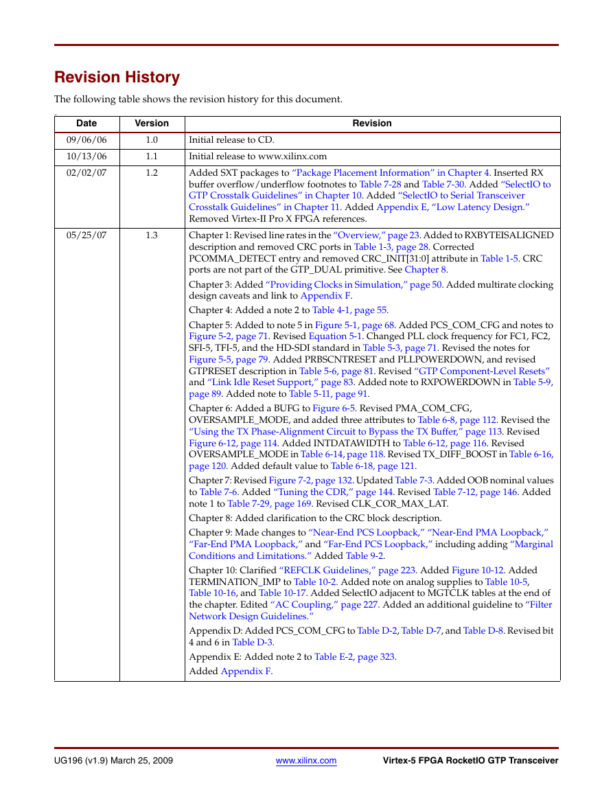
Revision History
The following table shows the revision history for this document.
an
Date
Version
09/06/06
10/13/06
02/02/07
1.0
1.1
1.2
05/25/07
1.3
Revision
Initial release to CD.
Initial release to www.xilinx.com
Added SXT packages to “Package Placement Information” in Chapter 4. Inserted RX
buffer overflow/underflow footnotes to Table 7-28 and Table 7-30. Added “SelectIO to
GTP Crosstalk Guidelines” in Chapter 10. Added “SelectIO to Serial Transceiver
Crosstalk Guidelines” in Chapter 11. Added Appendix E, “Low Latency Design.”
Removed Virtex-II Pro X FPGA references.
Chapter 1: Revised line rates in the “Overview,” page 23. Added to RXBYTEISALIGNED
description and removed CRC ports in Table 1-3, page 28. Corrected
PCOMMA_DETECT entry and removed CRC_INIT[31:0] attribute in Table 1-5. CRC
ports are not part of the GTP_DUAL primitive. See Chapter 8.
Chapter 3: Added “Providing Clocks in Simulation,” page 50. Added multirate clocking
design caveats and link to Appendix F.
Chapter 4: Added a note 2 to Table 4-1, page 55.
Chapter 5: Added to note 5 in Figure 5-1, page 68. Added PCS_COM_CFG and notes to
Figure 5-2, page 71. Revised Equation 5-1. Changed PLL clock frequency for FC1, FC2,
SFI-5, TFI-5, and the HD-SDI standard in Table 5-3, page 71. Revised the notes for
Figure 5-5, page 79. Added PRBSCNTRESET and PLLPOWERDOWN, and revised
GTPRESET description in Table 5-6, page 81. Revised “GTP Component-Level Resets”
and “Link Idle Reset Support,” page 83. Added note to RXPOWERDOWN in Table 5-9,
page 89. Added note to Table 5-11, page 91.
Chapter 6: Added a BUFG to Figure 6-5. Revised PMA_COM_CFG,
OVERSAMPLE_MODE, and added three attributes to Table 6-8, page 112. Revised the
“Using the TX Phase-Alignment Circuit to Bypass the TX Buffer,” page 113. Revised
Figure 6-12, page 114. Added INTDATAWIDTH to Table 6-12, page 116. Revised
OVERSAMPLE_MODE in Table 6-14, page 118. Revised TX_DIFF_BOOST in Table 6-16,
page 120. Added default value to Table 6-18, page 121.
Chapter 7: Revised Figure 7-2, page 132. Updated Table 7-3. Added OOB nominal values
to Table 7-6. Added “Tuning the CDR,” page 144. Revised Table 7-12, page 146. Added
note 1 to Table 7-29, page 169. Revised CLK_COR_MAX_LAT.
Chapter 8: Added clarification to the CRC block description.
Chapter 9: Made changes to “Near-End PCS Loopback,” “Near-End PMA Loopback,”
“Far-End PMA Loopback,” and “Far-End PCS Loopback,” including adding “Marginal
Conditions and Limitations.” Added Table 9-2.
Chapter 10: Clarified “REFCLK Guidelines,” page 223. Added Figure 10-12. Added
TERMINATION_IMP to Table 10-2. Added note on analog supplies to Table 10-5,
Table 10-16, and Table 10-17. Added SelectIO adjacent to MGTCLK tables at the end of
the chapter. Edited “AC Coupling,” page 227. Added an additional guideline to “Filter
Network Design Guidelines.”
Appendix D: Added PCS_COM_CFG to Table D-2, Table D-7, and Table D-8. Revised bit
4 and 6 in Table D-3.
Appendix E: Added note 2 to Table E-2, page 323.
Added Appendix F.
UG196 (v1.9) March 25, 2009
www.xilinx.com
Virtex-5 FPGA RocketIO GTP Transceiver
�
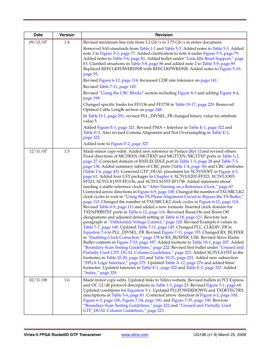
Date
Version
09/12/07
1.4
12/11/07
1.5
02/11/08
1.6
Revision
Revised maximum line rate from 3.2 Gb/s to 3.75 Gb/s in entire document.
Removed SAS standards from Table 1-1 and Table 5-3. Added notes to Table 5-3. Added
note 2 to Figure 5-3, page 77. Added clarification to note 4 under Figure 5-5, page 79.
Added notes to Table 5-6, page 81. Added bullet under “Link Idle Reset Support,” page
83. Clarified situations in Table 5-8, page 86 and added note 2 to Table 5-9, page 89.
Replaced REFCLKPOWERDNB with REFCLKPWRDNB. Added notes to Figure 5-10,
page 93.
Revised Figure 6-12, page 114. Increased CDR rate tolerance on page 141.
Revised Table 7-11, page 145.
Revised “Using the CRC Blocks” section including Figure 8-3 and adding Figure 8-4,
page 198.
Changed specific banks for FF1136 and FF1738 in Table 10-17, page 229. Removed
Optimal Cable Length section on page 248.
In Table D-1, page 291, revised PLL_DIVSEL_FB changed binary value for attribute
value 5.
Added Figure E-1, page 321. Revised PMA + Interface in Table E-1, page 322 and
Table E-2. Also revised Comma Alignment and Not Oversampling in Table E-2,
page 323.
Added note to Figure F-2, page 327.
Made minor copy-edits. Added new reference in Preface [Ref 1] and revised others.
Fixed directions of MGTRXN/MGTRXP and MGTTXN/MGTTXP ports in Table 1-2,
page 27. Corrected domain of RXELECIDLE port in Table 1-3, page 28 and Table 7-5,
page 136. Added summary tables of CRC ports (Table 1-4, page 36) and CRC attributes
(Table 1-6, page 43). Corrected GTP_DUAL placement for XC5VSX50T in Figure 4-3,
page 61. Added four LXT packages to Chapter 4: XC5VLX20T-FF323, XC5VLX30T-
FF323, XC5VLX155T-FF1136, and XC5VLX155T-FF1738. Added statement about
needing a stable reference clock to “After Turning on a Reference Clock,” page 87.
Corrected arrow directions in Figure 6-9, page 108. Changed the number of TXUSRCLK2
clock cycles to wait in “Using the TX Phase-Alignment Circuit to Bypass the TX Buffer,”
page 113. Changed the number of TXUSRCLK2 clock cycles in Figure 6-12, page 114.
Revised Table 6-9, page 113 and added a new footnote. Inserted clock domain for
TXENPRBSTST ports in Table 6-12, page 116. Reversed Boost On and Boost Off
designations and adjusted default setting in Table 6-18, page 121. Rewrote last
paragraph in “Differential Voltage Control,” page 120. Revised Example 6 values in
Table 7-7, page 140. Updated Table 7-11, page 145. Changed PLL_CLKDIV_FB in
Equation 7-6 to PLL_DIVSEL_FB. Revised Figure 7-11, page 155. Changed RX_BUFFER
in “Enabling Clock Correction,” page 178 to RX_BUFFER_USE. Revised Slave Elastic
Buffer contents in Figure 7-33, page 187. Added footnote to Table 10-1, page 207. Added
“Boundary-Scan Testing Guidelines,” page 222. Revised first bullet under “Unused and
Partially Used GTP_DUAL Column Guidelines,” page 223. Added XC5VLX155T to the
footnotes in Table 10-20, page 231 and Table 10-21, page 231. Added new subsection
“FPGA Logic Interface,” page 275. Updated Table A-12, page 276 and added three
footnotes. Updated latencies in Table E-1, page 322 and Table E-2, page 323. Added
“Index,” page 329.
Made minor copy-edits. Updated links to Xilinx website. Revised bullets in PCI Express
and OC-12/48 protocol descriptions in Table 1-1, page 23. Revised Figure 5-1, page 68.
Updated conditions for Equation 5-1. Updated PLLPOWERDOWN and TXDETECTRX
descriptions in Table 5-6, page 81. Corrected arrow direction in Figure 6-2, page 100,
Figure 6-3, page 100, Figure 7-34, page 190, and Figure 7-35, page 190. Rewrote
“Boundary-Scan Testing Guidelines,” page 222 and “Unused and Partially Used
GTP_DUAL Column Guidelines,” page 223.
Virtex-5 FPGA RocketIO GTP Transceiver
www.xilinx.com
UG196 (v1.9) March 25, 2009
�
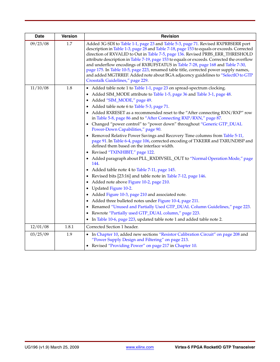
Date
Version
09/23/08
1.7
11/10/08
1.8
12/01/08
03/25/09
1.8.1
1.9
Revision
Added 3G-SDI to Table 1-1, page 23 and Table 5-3, page 71. Revised RXPRBSERR port
description in Table 1-3, page 28 and Table 7-18, page 153 to equals or exceeds. Corrected
direction of RXVALID to Out in Table 7-5, page 136. Revised PRBS_ERR_THRESHOLD
attribute description in Table 7-19, page 153 to equals or exceeds. Corrected the overflow
and underflow encodings of RXBUFSTATUS in Table 7-28, page 168 and Table 7-30,
page 175. In Table 10-5, page 223, renamed table title, corrected power supply names,
and added MGTRREF. Added note about BGA adjacency guidelines to “SelectIO to GTP
Crosstalk Guidelines,” page 229.
• Added table note 1 to Table 1-1, page 23 on spread-spectrum clocking.
• Added SIM_MODE attribute to Table 1-5, page 36 and Table 3-1, page 48.
• Added “SIM_MODE,” page 49.
• Added table note 6 to Table 5-3, page 71.
• Added RXRESET as a recommended reset to the “After connecting RXN/RXP” row
in Table 5-8, page 86 and to “After Connecting RXP/RXN,” page 87.
• Changed “power control” to “power down” throughout “Generic GTP_DUAL
Power-Down Capabilities,” page 90.
• Removed Relative Power Savings and Recovery Time columns from Table 5-11,
page 91. In Table 6-4, page 106, corrected encoding of TXKERR and TXRUNDISP and
defined them based on the interface width.
• Revised “TXINHIBIT,” page 122.
• Added paragraph about PLL_RXDIVSEL_OUT to “Normal Operation Mode,” page
144.
• Added table note 4 to Table 7-11, page 145.
• Revised bits [23:16] and table note in Table 7-12, page 146.
• Added note above Figure 10-2, page 210.
• Updated Figure 10-2.
• Added Figure 10-3, page 210 and associated note.
• Added three bulleted notes under Figure 10-4, page 211.
• Renamed “Unused and Partially Used GTP_DUAL Column Guidelines,” page 223.
• Rewrote “Partially used GTP_DUAL column,” page 223.
• In Table 10-6, page 223, updated table note 1 and added table note 2.
Corrected Section 1 header.
• In Chapter 10, added new sections “Resistor Calibration Circuit” on page 208 and
“Power Supply Design and Filtering” on page 213.
• Revised “Providing Power” on page 217 in Chapter 10.
UG196 (v1.9) March 25, 2009
www.xilinx.com
Virtex-5 FPGA RocketIO GTP Transceiver
�
Virtex-5 FPGA RocketIO GTP Transceiver
www.xilinx.com
UG196 (v1.9) March 25, 2009
�
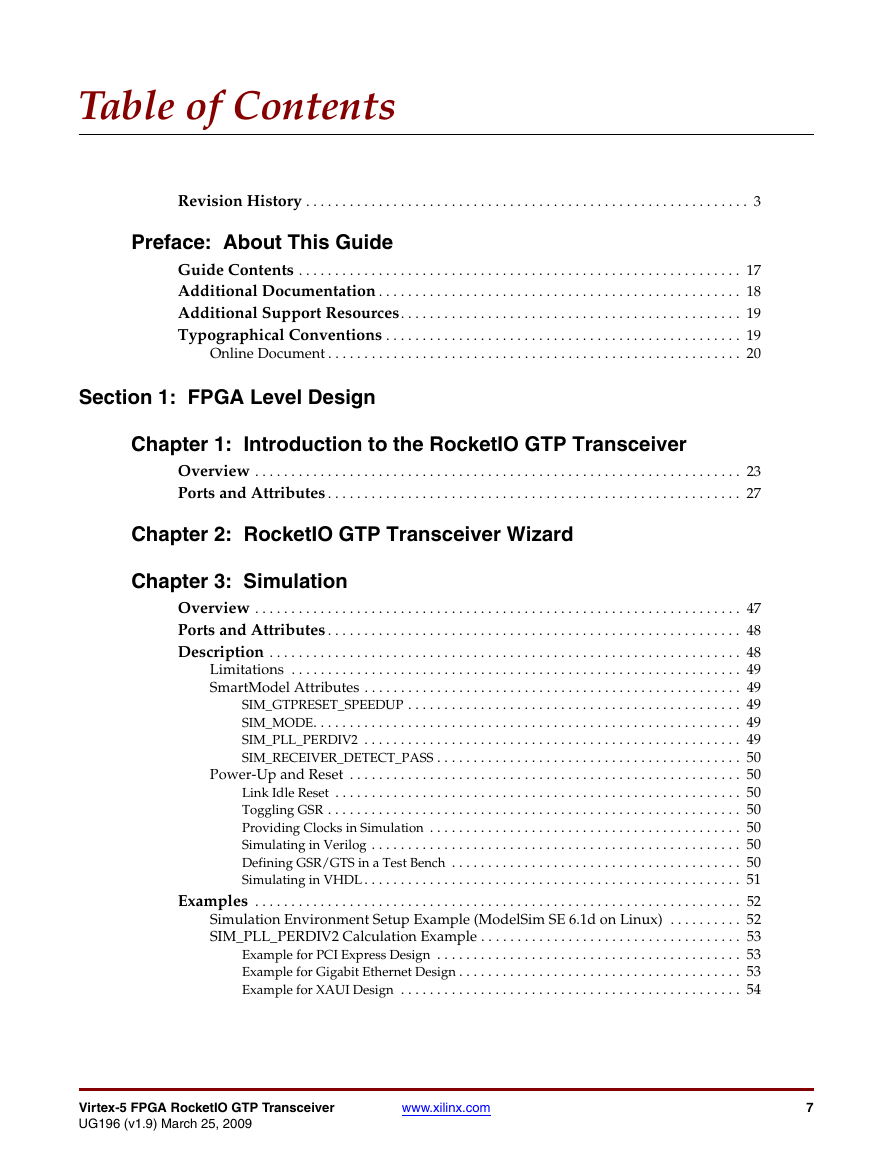
Table of Contents
Revision History . . . . . . . . . . . . . . . . . . . . . . . . . . . . . . . . . . . . . . . . . . . . . . . . . . . . . . . . . . . . . 3
Preface: About This Guide
Guide Contents . . . . . . . . . . . . . . . . . . . . . . . . . . . . . . . . . . . . . . . . . . . . . . . . . . . . . . . . . . . . . 17
Additional Documentation . . . . . . . . . . . . . . . . . . . . . . . . . . . . . . . . . . . . . . . . . . . . . . . . . . 18
Additional Support Resources. . . . . . . . . . . . . . . . . . . . . . . . . . . . . . . . . . . . . . . . . . . . . . . 19
Typographical Conventions . . . . . . . . . . . . . . . . . . . . . . . . . . . . . . . . . . . . . . . . . . . . . . . . . 19
Online Document . . . . . . . . . . . . . . . . . . . . . . . . . . . . . . . . . . . . . . . . . . . . . . . . . . . . . . . . . 20
Section 1: FPGA Level Design
Chapter 1: Introduction to the RocketIO GTP Transceiver
Overview . . . . . . . . . . . . . . . . . . . . . . . . . . . . . . . . . . . . . . . . . . . . . . . . . . . . . . . . . . . . . . . . . . . 23
Ports and Attributes . . . . . . . . . . . . . . . . . . . . . . . . . . . . . . . . . . . . . . . . . . . . . . . . . . . . . . . . . 27
Chapter 2: RocketIO GTP Transceiver Wizard
Chapter 3: Simulation
Overview . . . . . . . . . . . . . . . . . . . . . . . . . . . . . . . . . . . . . . . . . . . . . . . . . . . . . . . . . . . . . . . . . . . 47
Ports and Attributes . . . . . . . . . . . . . . . . . . . . . . . . . . . . . . . . . . . . . . . . . . . . . . . . . . . . . . . . . 48
Description . . . . . . . . . . . . . . . . . . . . . . . . . . . . . . . . . . . . . . . . . . . . . . . . . . . . . . . . . . . . . . . . . 48
Limitations . . . . . . . . . . . . . . . . . . . . . . . . . . . . . . . . . . . . . . . . . . . . . . . . . . . . . . . . . . . . . . 49
SmartModel Attributes . . . . . . . . . . . . . . . . . . . . . . . . . . . . . . . . . . . . . . . . . . . . . . . . . . . . 49
SIM_GTPRESET_SPEEDUP . . . . . . . . . . . . . . . . . . . . . . . . . . . . . . . . . . . . . . . . . . . . . . 49
SIM_MODE. . . . . . . . . . . . . . . . . . . . . . . . . . . . . . . . . . . . . . . . . . . . . . . . . . . . . . . . . . . 49
SIM_PLL_PERDIV2 . . . . . . . . . . . . . . . . . . . . . . . . . . . . . . . . . . . . . . . . . . . . . . . . . . . . 49
SIM_RECEIVER_DETECT_PASS . . . . . . . . . . . . . . . . . . . . . . . . . . . . . . . . . . . . . . . . . . 50
Power-Up and Reset . . . . . . . . . . . . . . . . . . . . . . . . . . . . . . . . . . . . . . . . . . . . . . . . . . . . . . 50
Link Idle Reset . . . . . . . . . . . . . . . . . . . . . . . . . . . . . . . . . . . . . . . . . . . . . . . . . . . . . . . . 50
Toggling GSR . . . . . . . . . . . . . . . . . . . . . . . . . . . . . . . . . . . . . . . . . . . . . . . . . . . . . . . . . 50
Providing Clocks in Simulation . . . . . . . . . . . . . . . . . . . . . . . . . . . . . . . . . . . . . . . . . . . 50
Simulating in Verilog . . . . . . . . . . . . . . . . . . . . . . . . . . . . . . . . . . . . . . . . . . . . . . . . . . . 50
Defining GSR/GTS in a Test Bench . . . . . . . . . . . . . . . . . . . . . . . . . . . . . . . . . . . . . . . . 50
Simulating in VHDL . . . . . . . . . . . . . . . . . . . . . . . . . . . . . . . . . . . . . . . . . . . . . . . . . . . . 51
Examples . . . . . . . . . . . . . . . . . . . . . . . . . . . . . . . . . . . . . . . . . . . . . . . . . . . . . . . . . . . . . . . . . . . 52
Simulation Environment Setup Example (ModelSim SE 6.1d on Linux) . . . . . . . . . . 52
SIM_PLL_PERDIV2 Calculation Example . . . . . . . . . . . . . . . . . . . . . . . . . . . . . . . . . . . . 53
Example for PCI Express Design . . . . . . . . . . . . . . . . . . . . . . . . . . . . . . . . . . . . . . . . . . 53
Example for Gigabit Ethernet Design . . . . . . . . . . . . . . . . . . . . . . . . . . . . . . . . . . . . . . . 53
Example for XAUI Design . . . . . . . . . . . . . . . . . . . . . . . . . . . . . . . . . . . . . . . . . . . . . . . 54
Virtex-5 FPGA RocketIO GTP Transceiver
UG196 (v1.9) March 25, 2009
www.xilinx.com
7
�
R
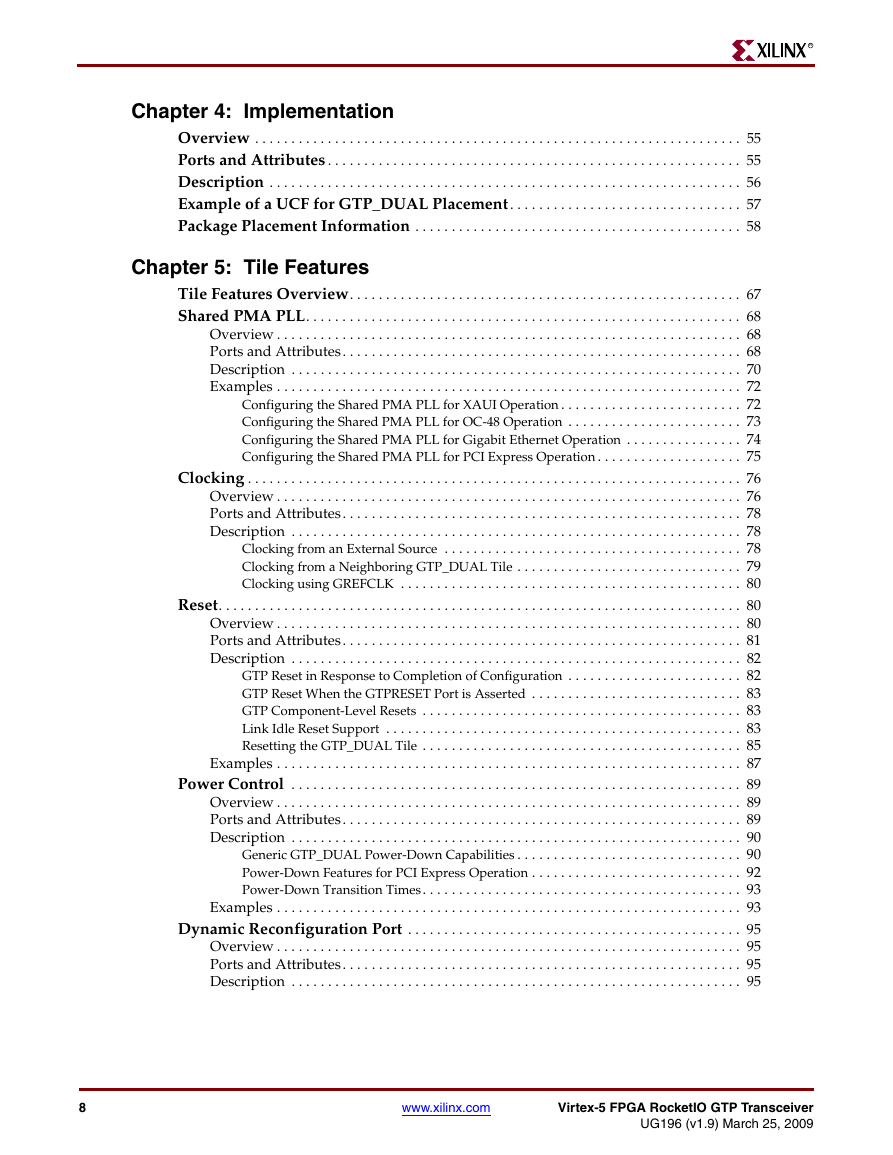
Chapter 4: Implementation
Overview . . . . . . . . . . . . . . . . . . . . . . . . . . . . . . . . . . . . . . . . . . . . . . . . . . . . . . . . . . . . . . . . . . . 55
Ports and Attributes . . . . . . . . . . . . . . . . . . . . . . . . . . . . . . . . . . . . . . . . . . . . . . . . . . . . . . . . . 55
Description . . . . . . . . . . . . . . . . . . . . . . . . . . . . . . . . . . . . . . . . . . . . . . . . . . . . . . . . . . . . . . . . . 56
Example of a UCF for GTP_DUAL Placement . . . . . . . . . . . . . . . . . . . . . . . . . . . . . . . . 57
Package Placement Information . . . . . . . . . . . . . . . . . . . . . . . . . . . . . . . . . . . . . . . . . . . . . 58
Chapter 5: Tile Features
Tile Features Overview. . . . . . . . . . . . . . . . . . . . . . . . . . . . . . . . . . . . . . . . . . . . . . . . . . . . . . 67
Shared PMA PLL. . . . . . . . . . . . . . . . . . . . . . . . . . . . . . . . . . . . . . . . . . . . . . . . . . . . . . . . . . . . 68
Overview . . . . . . . . . . . . . . . . . . . . . . . . . . . . . . . . . . . . . . . . . . . . . . . . . . . . . . . . . . . . . . . . 68
Ports and Attributes. . . . . . . . . . . . . . . . . . . . . . . . . . . . . . . . . . . . . . . . . . . . . . . . . . . . . . . 68
Description . . . . . . . . . . . . . . . . . . . . . . . . . . . . . . . . . . . . . . . . . . . . . . . . . . . . . . . . . . . . . . 70
Examples . . . . . . . . . . . . . . . . . . . . . . . . . . . . . . . . . . . . . . . . . . . . . . . . . . . . . . . . . . . . . . . . 72
Configuring the Shared PMA PLL for XAUI Operation . . . . . . . . . . . . . . . . . . . . . . . . . 72
Configuring the Shared PMA PLL for OC-48 Operation . . . . . . . . . . . . . . . . . . . . . . . . 73
Configuring the Shared PMA PLL for Gigabit Ethernet Operation . . . . . . . . . . . . . . . . 74
Configuring the Shared PMA PLL for PCI Express Operation . . . . . . . . . . . . . . . . . . . . 75
Clocking . . . . . . . . . . . . . . . . . . . . . . . . . . . . . . . . . . . . . . . . . . . . . . . . . . . . . . . . . . . . . . . . . . . . 76
Overview . . . . . . . . . . . . . . . . . . . . . . . . . . . . . . . . . . . . . . . . . . . . . . . . . . . . . . . . . . . . . . . . 76
Ports and Attributes. . . . . . . . . . . . . . . . . . . . . . . . . . . . . . . . . . . . . . . . . . . . . . . . . . . . . . . 78
Description . . . . . . . . . . . . . . . . . . . . . . . . . . . . . . . . . . . . . . . . . . . . . . . . . . . . . . . . . . . . . . 78
Clocking from an External Source . . . . . . . . . . . . . . . . . . . . . . . . . . . . . . . . . . . . . . . . . 78
Clocking from a Neighboring GTP_DUAL Tile . . . . . . . . . . . . . . . . . . . . . . . . . . . . . . . 79
Clocking using GREFCLK . . . . . . . . . . . . . . . . . . . . . . . . . . . . . . . . . . . . . . . . . . . . . . . 80
Reset. . . . . . . . . . . . . . . . . . . . . . . . . . . . . . . . . . . . . . . . . . . . . . . . . . . . . . . . . . . . . . . . . . . . . . . . 80
Overview . . . . . . . . . . . . . . . . . . . . . . . . . . . . . . . . . . . . . . . . . . . . . . . . . . . . . . . . . . . . . . . . 80
Ports and Attributes. . . . . . . . . . . . . . . . . . . . . . . . . . . . . . . . . . . . . . . . . . . . . . . . . . . . . . . 81
Description . . . . . . . . . . . . . . . . . . . . . . . . . . . . . . . . . . . . . . . . . . . . . . . . . . . . . . . . . . . . . . 82
GTP Reset in Response to Completion of Configuration . . . . . . . . . . . . . . . . . . . . . . . . 82
GTP Reset When the GTPRESET Port is Asserted . . . . . . . . . . . . . . . . . . . . . . . . . . . . . 83
GTP Component-Level Resets . . . . . . . . . . . . . . . . . . . . . . . . . . . . . . . . . . . . . . . . . . . . 83
Link Idle Reset Support . . . . . . . . . . . . . . . . . . . . . . . . . . . . . . . . . . . . . . . . . . . . . . . . . 83
Resetting the GTP_DUAL Tile . . . . . . . . . . . . . . . . . . . . . . . . . . . . . . . . . . . . . . . . . . . . 85
Examples . . . . . . . . . . . . . . . . . . . . . . . . . . . . . . . . . . . . . . . . . . . . . . . . . . . . . . . . . . . . . . . . 87
Power Control . . . . . . . . . . . . . . . . . . . . . . . . . . . . . . . . . . . . . . . . . . . . . . . . . . . . . . . . . . . . . . 89
Overview . . . . . . . . . . . . . . . . . . . . . . . . . . . . . . . . . . . . . . . . . . . . . . . . . . . . . . . . . . . . . . . . 89
Ports and Attributes. . . . . . . . . . . . . . . . . . . . . . . . . . . . . . . . . . . . . . . . . . . . . . . . . . . . . . . 89
Description . . . . . . . . . . . . . . . . . . . . . . . . . . . . . . . . . . . . . . . . . . . . . . . . . . . . . . . . . . . . . . 90
Generic GTP_DUAL Power-Down Capabilities . . . . . . . . . . . . . . . . . . . . . . . . . . . . . . . 90
Power-Down Features for PCI Express Operation . . . . . . . . . . . . . . . . . . . . . . . . . . . . . 92
Power-Down Transition Times. . . . . . . . . . . . . . . . . . . . . . . . . . . . . . . . . . . . . . . . . . . . 93
Examples . . . . . . . . . . . . . . . . . . . . . . . . . . . . . . . . . . . . . . . . . . . . . . . . . . . . . . . . . . . . . . . . 93
Dynamic Reconfiguration Port . . . . . . . . . . . . . . . . . . . . . . . . . . . . . . . . . . . . . . . . . . . . . . 95
Overview . . . . . . . . . . . . . . . . . . . . . . . . . . . . . . . . . . . . . . . . . . . . . . . . . . . . . . . . . . . . . . . . 95
Ports and Attributes. . . . . . . . . . . . . . . . . . . . . . . . . . . . . . . . . . . . . . . . . . . . . . . . . . . . . . . 95
Description . . . . . . . . . . . . . . . . . . . . . . . . . . . . . . . . . . . . . . . . . . . . . . . . . . . . . . . . . . . . . . 95
8
www.xilinx.com
Virtex-5 FPGA RocketIO GTP Transceiver
UG196 (v1.9) March 25, 2009
�





 2023年江西萍乡中考道德与法治真题及答案.doc
 2012年重庆南川中考生物真题及答案.doc
 2013年江西师范大学地理学综合及文艺理论基础考研真题.doc
 2020年四川甘孜小升初语文真题及答案I卷.doc
 2020年注册岩土工程师专业基础考试真题及答案.doc
 2023-2024学年福建省厦门市九年级上学期数学月考试题及答案.doc
 2021-2022学年辽宁省沈阳市大东区九年级上学期语文期末试题及答案.doc
 2022-2023学年北京东城区初三第一学期物理期末试卷及答案.doc
 2018上半年江西教师资格初中地理学科知识与教学能力真题及答案.doc
 2012年河北国家公务员申论考试真题及答案-省级.doc
 2020-2021学年江苏省扬州市江都区邵樊片九年级上学期数学第一次质量检测试题及答案.doc
 2022下半年黑龙江教师资格证中学综合素质真题及答案.doc