Back to List of Contents
SAFETY PRECAUTIONS
1. DEFINITION OF WARNING, CAUTION, AND NOTE
2. GENERAL WARNINGS AND NOTES
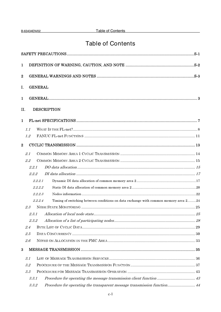
Table of Contents
I. GENERAL
1. GENERAL
II. DESCRIPTION
1. FL-net SPECIFICATIONS
1.1 What Is the FL-net?
1.2 FANUC FL-net Functions
2. CYCLIC TRANSMISSION
2.1 Common Memory Area 1 Cyclic Transmission
2.2 Common Memory Area 2 Cyclic Transmission
2.2.1 DO data allocation
2.2.2 DI data allocation
2.2.2.1 Dynamic DI data allocation of common memory area 2
2.2.2.2 Static DI data allocation of common memory area 2
2.2.2.3 Nodes information
2.2.2.4 Timing of switching between conditions on data exchange with common memory area 2
2.3 Node State Monitoring
2.3.1 Allocation of local node state
2.3.2 Allocation of a list of participating nodes
2.4 Byte List of Cyclic Data
2.5 Data Concurrency
2.6 Notes on Allocation in the PMC Area
3. MESSAGE TRANSMISSION
3.1 List of Message Transmission Services
3.2 Procedure of the Message Transmission Function
3.3 Procedure for Message Transmission Operation
3.3.1 Procedure for operating the message transmission client function
3.3.2 Procedure for operating the transparent message transmission function
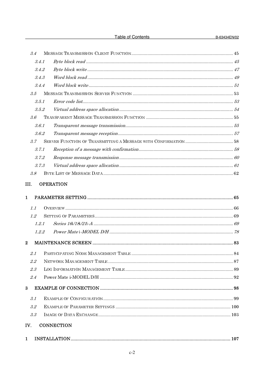
3.4 Message Transmission Client Function
3.4.1 Byte block read
3.4.2 Byte block write
3.4.3 Word block read
3.4.4 Word block write
3.5 Message Transmission Server Function
3.5.1 Error code list
3.5.2 Virtual address space allocation
3.6 Transparent Message Transmission Function
3.6.1 Transparent message transmission
3.6.2 Transparent message reception
3.7 Server Function of Transmitting a Message with Confirmation
3.7.1 Reception of a message with confirmation
3.7.2 Response message transmission
3.7.3 Virtual address space allocation
3.8 Byte List of Message Data
III. OPERATION
1. PARAMETER SETTING
1.1 Overview
1.2 Setting of Parameters
1.2.1 Series 16i/18i/21i-A
1.2.2 Power Mate i-MODEL D/H
2. MAINTENANCE SCREEN
2.1 Participating Node Management Table
2.2 Network Management Table
2.3 Log Information Management Table
2.4 Power Mate i-MODEL D/H
3. EXAMPLE OF CONNECTION
3.1 Example of Configuration
3.2 Example of Parameter Settings
3.3 Image of Data Exchange
IV. CONNECTION
1. INSTALLATION
1.1 Specifications
1.2 Installation
2. CONNECTION OF THE COMMUNICATION FUNCTION
2.1 Connection to Ethernet
2.2 Routing of the Ethernet Cable
2.3 Pin Allocation of the 10BASE-T Connector (CD38N)
2.4 Twisted Pair Cable Specifications
2.4.1 Cable connection
2.4.2 Cable wire
2.4.3 Connector Specifications
2.4.4 Hub
2.5 Noise Protection
2.5.1 Signal line separation
2.5.2 Cable clamping and shield processing
2.5.3 Network installation
V. MAINTENANCE
1. HARDWARE
1.1 Layout of Components
1.2 LED Indications and Meanings
1.3 Setting Pin
INDEX



 2023年江西萍乡中考道德与法治真题及答案.doc
 2012年重庆南川中考生物真题及答案.doc
 2013年江西师范大学地理学综合及文艺理论基础考研真题.doc
 2020年四川甘孜小升初语文真题及答案I卷.doc
 2020年注册岩土工程师专业基础考试真题及答案.doc
 2023-2024学年福建省厦门市九年级上学期数学月考试题及答案.doc
 2021-2022学年辽宁省沈阳市大东区九年级上学期语文期末试题及答案.doc
 2022-2023学年北京东城区初三第一学期物理期末试卷及答案.doc
 2018上半年江西教师资格初中地理学科知识与教学能力真题及答案.doc
 2012年河北国家公务员申论考试真题及答案-省级.doc
 2020-2021学年江苏省扬州市江都区邵樊片九年级上学期数学第一次质量检测试题及答案.doc
 2022下半年黑龙江教师资格证中学综合素质真题及答案.doc