NXP Semiconductors
Document Number: IMXVPUAPI
Rev. 0, 10/2016
i.MX VPU Application
Programming Interface Linux®
Reference Manual
Contents
1
2
3
4
5
Overview....................................................................1
Host Interface............................................................ 5
API Features............................... ...............................7
VPU Control.............................. ............................. 68
Revision History......................... ............................ 86
1 Overview
This section discusses the capabilities of i.MX 6 series VPU,
and explains its block diagram.
The i.MX 6 series Video Processing Unit (VPU) is a high
performance multi-standard video decoder and encoder engine
that performs multiple standard decoding and encoding
operations. VPU codec is fully compliant with H.264
BP/MP/HP, VC-1 SP/MP/AP, MPEG-4 SP/ASP except GMC,
DivX (Xvid), MPEG-1/2, VP8, AVS and MJPEG decoding
and H.264, MPEG-4, H.263, and MJPG encoding. VPU
supports up to full HD 1920x1080 60i or 30p decoding and
1920x1088 encoding. It can encode or decode multiple video
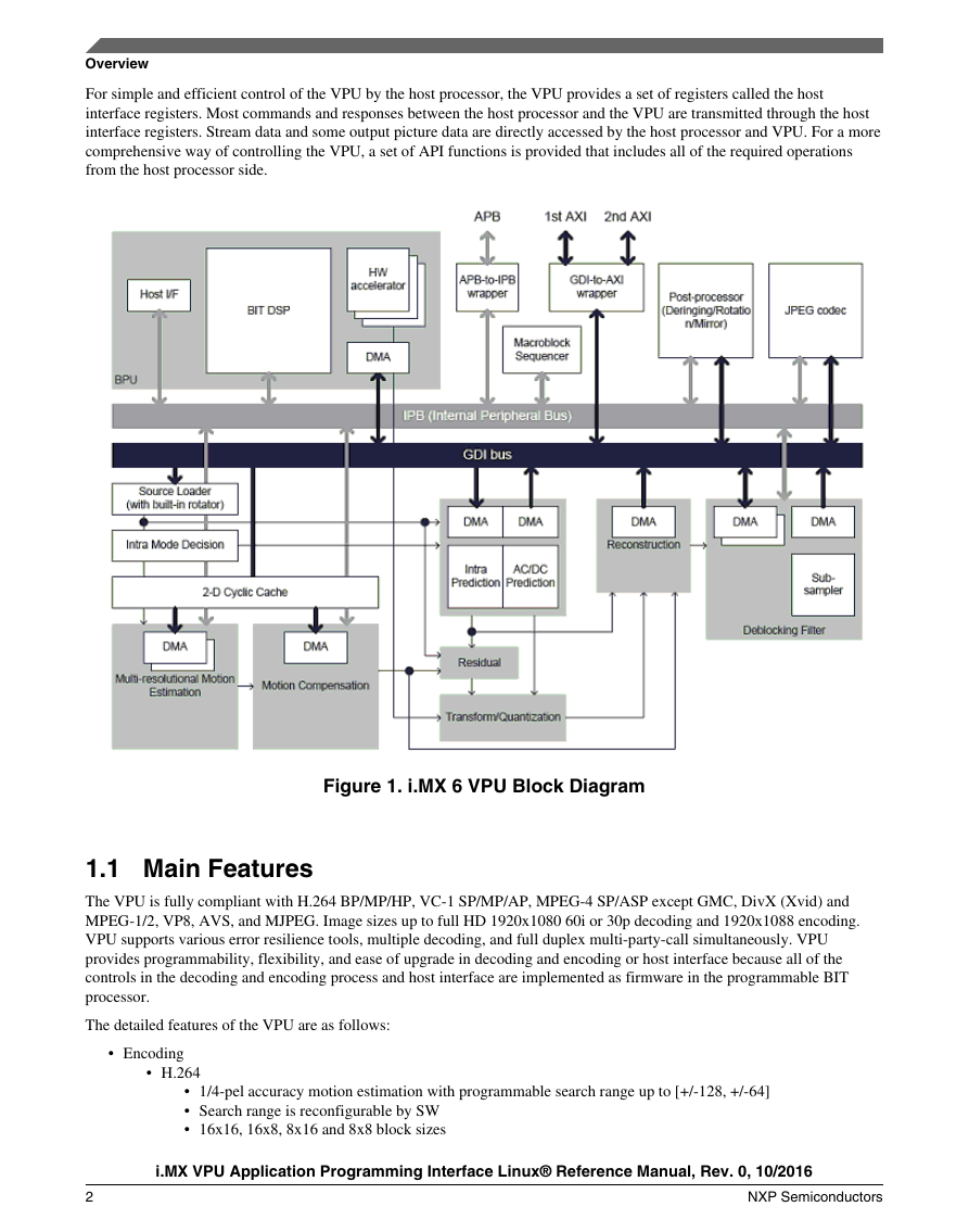
clips with multiple standards simultaneously. A block diagram
of the i.MX 6 series VPU is shown in figure below.
The VPU connects with the system through the 32-bit
AMBA3 APB bus for system control and the 64-bit AMBA3
AXI for data throughput. VPU also takes advantage of on-chip
memories to achieve high performance.
Most video hardware blocks in VPU are optimally designed
for shared usage between different video standards which
provides ultra low power and low gate count with powerful
performance. As shown in figure below, VPU has a 16-bit
DSP core, the BIT processor, which controls the internal video
codec operations.
�
Overview
For simple and efficient control of the VPU by the host processor, the VPU provides a set of registers called the host
interface registers. Most commands and responses between the host processor and the VPU are transmitted through the host
interface registers. Stream data and some output picture data are directly accessed by the host processor and VPU. For a more
comprehensive way of controlling the VPU, a set of API functions is provided that includes all of the required operations
from the host processor side.
Figure 1. i.MX 6 VPU Block Diagram
1.1 Main Features
The VPU is fully compliant with H.264 BP/MP/HP, VC-1 SP/MP/AP, MPEG-4 SP/ASP except GMC, DivX (Xvid) and
MPEG-1/2, VP8, AVS, and MJPEG. Image sizes up to full HD 1920x1080 60i or 30p decoding and 1920x1088 encoding.
VPU supports various error resilience tools, multiple decoding, and full duplex multi-party-call simultaneously. VPU
provides programmability, flexibility, and ease of upgrade in decoding and encoding or host interface because all of the
controls in the decoding and encoding process and host interface are implemented as firmware in the programmable BIT
processor.
The detailed features of the VPU are as follows:
• Encoding
• H.264
• 1/4-pel accuracy motion estimation with programmable search range up to [+/-128, +/-64]
• Search range is reconfigurable by SW
• 16x16, 16x8, 8x16 and 8x8 block sizes
i.MX VPU Application Programming Interface Linux® Reference Manual, Rev. 0, 10/2016
2
NXP Semiconductors
�
Overview
• Configurable block sizes
• Only one reference frame for motion estimation
• Intra-prediction
• Luma I4x4 Mode : 9 modes
• Luma I16x16 Mode : 3 modes (Vertical, Horizon, DC)
• Chroma Mode : 3 modes (Vertical, Horizon, DC)
• Minimum encoding image size is 96 pixels in horizontal and 16 pixels in vertical
• FMO/ASO tool of H.264 is not supported
• MPEG-4
• AC/DC prediction
• 1/2-pel accuracy motion estimation with search range up to [+/-128, +/-64]
• Search range is reconfigurable by SW
• H.263
• H.263 Baseline profile + Annex J, K (RS=0 and ASO=0), and T
• 48x32 pixel minimum encoding image size (48 pixels horizontal and 32 pixels vertical)
• Decoding
• H.264
• Fully compatible with the ITU-T Recommendation H.264 specification in BP/MP and HP
• CABAC/CAVLC
• Supports MVC Stereo High profile
• Variable block size-16x16, 16x8, 8x16, 8x8, 8x4, 4x8 and 4x4
• Error detection, concealment and error resilience tools
• VC1
• All VC-1 profile features-SMPTE Proposed SMPTE Standard for Television: VC-1 Compressed Video
Bitstream format and Decoding Process
• Simple/Main/Advanced Profile
• MPEG-4
• Simple/Advanced Simple profile except GMC
• H.263 Baseline profile + Annex I, J, K (except RS/ASO), and T
• DivX version 3.x to 6.x
• Xvid
• MPEG-2
• Fully compatible with ISO/IEC 13182-2 MPEG2 specification in main profile
• I,P and B frame
• Field coded picture (interlaced) and fame coded picture
• AVS
• Supports Jizhun profile level 6.2 (exclude 422 use case)
• VP8
• Fully compatible with VP8 decoder specification
• Supporting both simple and normal in-loop deblocking
• 64x64 pixel minimum decoding size
• JPEG tools
• MJPEG Baseline Process Encoder and Decoder
• Baseline ISO/IEC 10918-1 JPEG compliance
• Support 1 or 3 color components
• 3 component in a scan (interleaved only)
• 8 bit samples for each component
• Support 4:2:0, 4:2:2, 2:2:4, 4:4:4 and 4:0:0 color format (max. six 8x8 blocks in one MCU)
• Minimum encoding size is 16x16 pixels.
• Value added features
• De-ringing
• Pre/Post rotator/mirror
• Built-in de-blocking filter for MPEG-2/MPEG-4 and DivX
• Programmability
i.MX VPU Application Programming Interface Linux® Reference Manual, Rev. 0, 10/2016
NXP Semiconductors
3
�
Overview
• 16-bit DSP processor dedicated to processing bitstream and controlling the codec hardware
• General purpose registers and interrupt for communication to and from a host processor
• Optimal external memory accesses
• Configurable frame buffer formats (linear or tiled) for longer burst-length
• 2D cache for motion estimation and compensation to reduce external memory accesses
• Secondary AXI port for on-chip memory to enhance performance
• Performance
• All video decoder standards up to 1920x1088 @ 30 fps at 266 MHz
• H264 encoder standards up to 1920x1088 @ 30 fps at 266 MHz, MPEG4 encoder up to 720p@30fps at 266MHz
• MJPG decoder on 4:4:4 supports 120M pixel per second @ 266MHz
• MJPG encoder on 4:4:4 supports 160M pixel per second @ 266MHz
• Interrupt
• Interrupt from and to external host processor or interrupt controller
1.2 Programmability
The VPU has an internal DSP called the BIT processor which controls the internal hardware blocks for video decoder
operations. The operation of the BIT processor is determined by the dedicated microcode called the BIT firmware. VPU has a
complete set of BIT firmware code as well as a complete set of VPU control functions called VPU API. Therefore,
application developers do not need to manage codec-specific issues on host processor.
1.2.1 Frame-Based Processing
The BIT processor completes decoding operations on a frame-by-frame basis, which allows low level independence of VPU
operations from the host processor. While frame operations are running, there is no need for communication between the host
processor and the VPU. Therefore, VPU does not burden the host processor during decoder operations.
After issuing a picture processing command, the host application performs its own operations until it is ready for the next
picture processing operation or until it receives an interrupt from VPU informing the host processor of completion of the
picture processing.
1.2.2 Program Memory Management
The VPU has its own program memory to load BIT firmware for supporting application-specific operations. In order to use
this internal memory efficiently, the BIT firmware has a dynamic re-loading scheme which enables the VPU to have a small
amount of program memory.
For example, if a MPEG-2 decoder operation is running on VPU, then VPU program memory is filled by the MPEG-2
decoder firmware inside VPU. If a H.264 decoder operation is newly issued, then the BIT processor automatically loads the
H.264 decoder firmware from the SDRAM to program memory.
Because of the frame-based operation of VPU, the maximum rate of this dynamic reloading operation is approximately 30
times per second in a single instance decoder use case. Since the amount of BIT firmware for one decoder standard is smaller
than 16 Kytes, this is not a large burden for the VPU operations in performance and memory bandwidth.
i.MX VPU Application Programming Interface Linux® Reference Manual, Rev. 0, 10/2016
4
NXP Semiconductors
�
Host Interface
1.2.3 Multi-Instances
The VPU supports multiple instances which can be helpful for multi-channel decoder applications. In order to support this
multi-instance operation, the BIT processor uses an internal context parameter set for each decoder instance. When creating a
new instance and starting a picture processing operation, a set of context parameters is created and updated automatically
within VPU. This internal context management scheme allows different decoder tasks running on the host processor to
control VPU operations independently with their own instance numbers.
When creating a new instance, an application task receives a new handle specifying an instance if a new handle is available
on the VPU. All the subsequent operations for the given application task are handled separately by VPU using this task-
specific handle. When writing a VPU driver, this handle can be regard as a device-ID or a port-ID of the VPU for each task.
Since the VPU can only perform one picture processing task at a time, the application task should check if VPU is ready
before starting a new picture operation. An application can easily terminate a single task on VPU by calling a function for
closing a certain instance.
2 Host Interface
This section describes the interfaces used by host processor to control i.MX 6 VPU.
This section presents a general description of the host interfaces provided for a host processor to control i.MX 6 VPU.
2.1 Communication Models
VPU requires a dedicated path for exchanging data and/or messages between the host processor and VPU. VPU uses shared
memory for exchanging data between the host processor and VPU. This shared memory is accessible through ABMA host
bus. Bitstream data and frame data are exchanged using this shared memory space.
Independent of data exchange path, a dedicated path for messages between the host processor and VPU is provided using a
set of VPU registers called the host interface registers. All commands and responses between the host processor and VPU are
exchanged through these registers as shown in figure below.
i.MX VPU Application Programming Interface Linux® Reference Manual, Rev. 0, 10/2016
NXP Semiconductors
5
�
Host Interface
Figure 2. Data and Message Exchange Between Host and VPU
All bitstream and picture data is accessed directly by the host processor and VPU. The related information about the data
transfer as well as command and responses is exchanged through the host interface. The host interface of the VPU uses a set
of registers accessible from the host processor. Some of these host registers are used for exchanging actual command and
responses and other registers are used to give information about the internal status of the VPU to host processor. Firmware
running on the BIT processor is well-optimized for a given set of commands and responses.
2.1.1 Data Handling
All of the pixel data or stream data transactions are performed by the host processor or VPU through the shared memory
space in SDRAM. In order to assure safe transactions between the host processor and VPU, all the required information is
stored in the host interface registers. Generally, these transactions are one-directional transactions: the host or VPU writes the
data and the other reads the data on a single data buffer. Therefore, transactions are easily and safely controlled by using a
pair of read and write pointers.
Just as common data buffers in shared memory, the BIT processor requires a certain amount of memory for processing called
the working buffer. The working buffer can only be accessed by VPU. In addition, frame buffers used in picture decoding are
managed exclusively by VPU which ensures safe decoding.
For proper streaming, the available free space in the decoder stream buffer can be accessed using the buffer read pointer,
write pointer, and buffer size. A set of APIs is provided for this purpose that can be called by the application anytime.
2.1.2 Host Interface Registers
A set of commands is provided for controlling codec operations on a frame-by-frame basis together with the corresponding
responses. Host interface registers can be partitioned into three categories as follows:
• BIT processor control registers update or show BIT processor status to host processors. Most of these registers are used
for initializing BIT processor during boot-up.
i.MX VPU Application Programming Interface Linux® Reference Manual, Rev. 0, 10/2016
6
NXP Semiconductors
�
• BIT processor global registers store all the global variables which are reserved even while an active instance is
changed. All the buffer addresses and some global options are safely stored in these registers.
• BIT processor command I/O registers are overwritten or updated whenever a new command is transmitted from the
host processor. All commands with input arguments and all corresponding responses with return values are handled
using these registers.
In addition, command I/O registers are used in a pre-defined way for each command to control VPU.
API Features
2.2 API-Based VPU Control
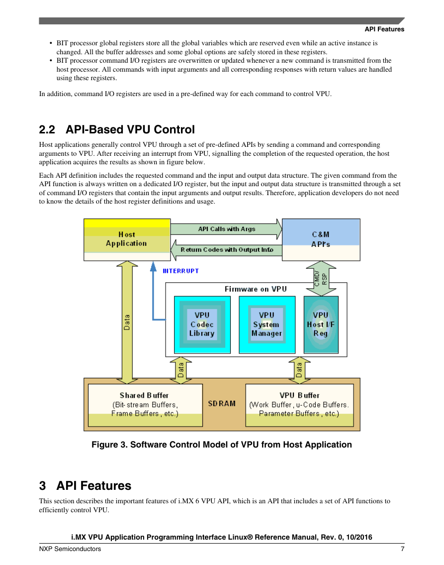
Host applications generally control VPU through a set of pre-defined APIs by sending a command and corresponding
arguments to VPU. After receiving an interrupt from VPU, signalling the completion of the requested operation, the host
application acquires the results as shown in figure below.
Each API definition includes the requested command and the input and output data structure. The given command from the
API function is always written on a dedicated I/O register, but the input and output data structure is transmitted through a set
of command I/O registers that contain the input arguments and output results. Therefore, application developers do not need
to know the details of the host register definitions and usage.
Figure 3. Software Control Model of VPU from Host Application
3 API Features
This section describes the important features of i.MX 6 VPU API, which is an API that includes a set of API functions to
efficiently control VPU.
i.MX VPU Application Programming Interface Linux® Reference Manual, Rev. 0, 10/2016
NXP Semiconductors
7
�
API Features
A set of API functions is provided to efficiently control VPU. VPU API covers all functions of the i.MX 6 VPU. This API-
based approach speeds up the development process of application software. Important features of the API for i.MX 6 VPU
are summarized in the following sections.
3.1 Simple Software Control
i.MX 6 VPU API provides a simple way to control the i.MX 6 VPU and avoid errors in application software. The host
application does not need to know the details of the i.MX 6 VPU internal operations. For example, in order to initialize VPU,
an application simply calls API for initialization, vpu_Init(), and no additional information is required for calling this API.
vpu_Init() API performs all the required steps for initializing i.MX 6 VPU. When issuing a picture decoder operation, the
application simply changes some variables included in the well-defined input data structure.
3.1.1 Handling Multi-Instances
The i.MX 6 VPU supports multiple instances for decoding and encoding at the same time, which can be used in multiple
decoding and encoding and multi-party call applications. To support multi-instance operations,i.MX 6 VPU API provides a
full set of functions for handling the instances with ease. When opening a new instance, the application receives a handle
specifying the new instance provided a new handle is available at that time. The operations for a given instance are separately
controlled using the corresponding handle. An application can easily terminate a single task on VPU by calling a function for
closing a certain instance.
3.1.2 Frame-Based Codec Processing
i.MX 6 VPU completes decoding and encoding operation on a frame-by-frame basis, which enables low level independence
of the VPU operations from the host processor. While frame processing operation are running, there is no need for
communication between the host processor and VPU. Therefore, VPU does not burden the host processor during decoding
and encoding operations.
3.2 Type Definitions
This section describes the types and structures used in VPU API.
3.2.1 Type Definitions (common data types)
This section describes the common data types used in the VPU API functions.
3.2.1.1 Uint8
typedef unsigned char Uint8;
Description
8-bit unsigned integer type used for declaring pixel data.
i.MX VPU Application Programming Interface Linux® Reference Manual, Rev. 0, 10/2016
8
NXP Semiconductors
�



 2023年江西萍乡中考道德与法治真题及答案.doc
 2012年重庆南川中考生物真题及答案.doc
 2013年江西师范大学地理学综合及文艺理论基础考研真题.doc
 2020年四川甘孜小升初语文真题及答案I卷.doc
 2020年注册岩土工程师专业基础考试真题及答案.doc
 2023-2024学年福建省厦门市九年级上学期数学月考试题及答案.doc
 2021-2022学年辽宁省沈阳市大东区九年级上学期语文期末试题及答案.doc
 2022-2023学年北京东城区初三第一学期物理期末试卷及答案.doc
 2018上半年江西教师资格初中地理学科知识与教学能力真题及答案.doc
 2012年河北国家公务员申论考试真题及答案-省级.doc
 2020-2021学年江苏省扬州市江都区邵樊片九年级上学期数学第一次质量检测试题及答案.doc
 2022下半年黑龙江教师资格证中学综合素质真题及答案.doc