Cover Page
Title Page
About IEEE Std 1364-2001 Version C and the Errata
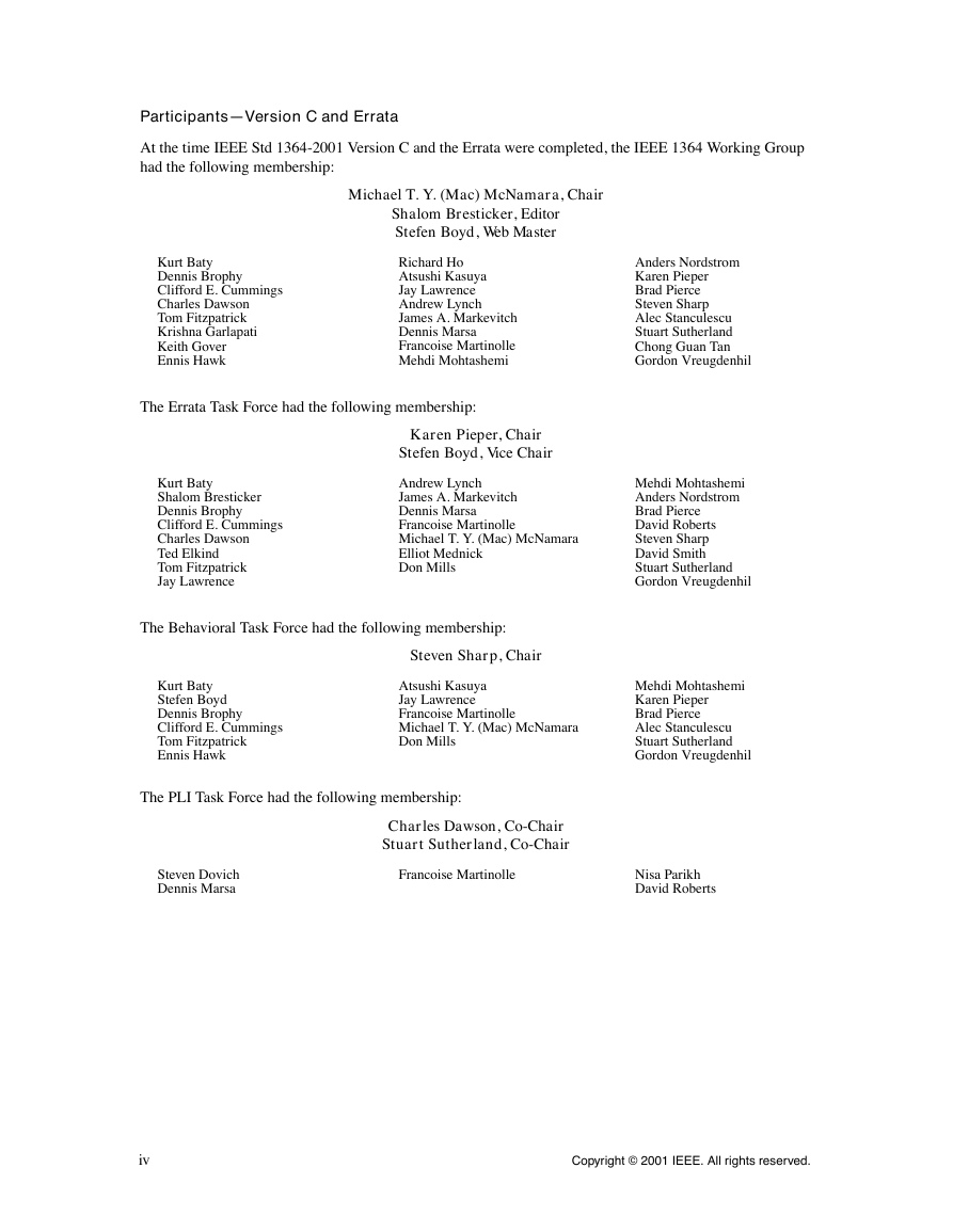
Participants—Version C and Errata
Introduction
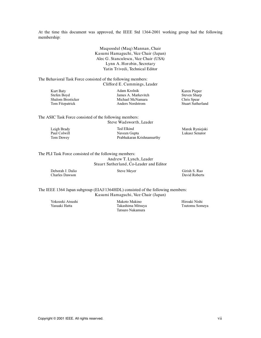
Participants
CONTENTS
1. Overview
1.1 Objectives of this standard
1.2 Conventions used in this standard
1.3 Syntactic description
1.4 Contents of this standard
1.5 Header file listings
1.6 Examples
1.7 Prerequisites
2. Lexical conventions
2.1 Lexical tokens
2.2 White space
2.3 Comments
2.4 Operators
2.5 Numbers
2.5.1 Integer constants
2.5.2 Real constants
2.5.3 Conversion
2.6 Strings
2.6.1 String variable declaration
2.6.2 String manipulation
2.6.3 Special characters in strings
2.7 Identifiers, keywords, and system names
2.7.1 Escaped identifiers
2.7.2 Generated identifiers
2.7.3 Keywords
2.7.4 System tasks and functions
2.7.5 Compiler directives
2.8 Attributes
2.8.1 Examples
2.8.2 Syntax
3. Data types
3.1 Value set
3.2 Nets and variables
3.2.1 Net declarations
3.2.2 Variable declarations
3.3 Vectors
3.3.1 Specifying vectors
3.3.2 Vector net accessibility
3.4 Strengths
3.4.1 Charge strength
3.4.2 Drive strength
3.5 Implicit declarations
3.6 Net initialization
3.7 Net types
3.7.1 Wire and tri nets
3.7.2 Wired nets
3.7.3 Trireg net
3.7.3.1 Capacitive networks
3.7.3.2 Ideal capacitive state and charge decay
3.7.4 Tri0 and tri1 nets
3.7.5 Supply nets
3.8 Regs
3.9 Integers, reals, times, and realtimes
3.9.1 Operators and real numbers
3.9.2 Conversion
3.10 Arrays
3.10.1 Net arrays
3.10.2 reg and variable arrays
3.10.3 Memories
3.10.3.1 Array examples
3.10.3.1.1 Array declarations
3.10.3.1.2 Assignment to array elements
3.10.3.1.3 Memory differences
3.11 Parameters
3.11.1 Module parameters
3.11.2 Local parameters - localparam
3.11.3 Specify parameters
3.12 Name spaces
4. Expressions
4.1 Operators
4.1.1 Operators with real operands
4.1.2 Operator precedence
4.1.3 Using integer numbers in expressions
4.1.4 Expression evaluation order
4.1.5 Arithmetic operators
4.1.6 Arithmetic expressions with regs and integers
4.1.7 Relational operators
4.1.8 Equality operators
4.1.9 Logical operators
4.1.10 Bit-wise operators
4.1.11 Reduction operators
4.1.12 Shift operators
4.1.13 Conditional operator
4.1.14 Concatenations
4.1.15 Event or
4.2 Operands
4.2.1 Vector bit-select and part-select addressing
4.2.2 Array and memory addressing
4.2.3 Strings
4.2.3.1 String operations
4.2.3.2 String value padding and potential problems
4.2.3.3 Null string handling
4.3 Minimum, typical, and maximum delay expressions
4.4 Expression bit lengths
4.4.1 Rules for expression bit lengths
4.4.2 An example of an expression bit-length problem
4.4.3 Example of self-determined expressions
4.5 Signed expressions
4.5.1 Rules for expression types
4.5.2 Steps for evaluating an expression
4.5.3 Steps for evaluating an assignment
4.5.4 Handling X and Z in signed expressions
5. Scheduling semantics
5.1 Execution of a model
5.2 Event simulation
5.3 The stratified event queue
5.4 The Verilog simulation reference model
5.4.1 Determinism
5.4.2 Nondeterminism
5.5 Race conditions
5.6 Scheduling implication of assignments
5.6.1 Continuous assignment
5.6.2 Procedural continuous assignment
5.6.3 Blocking assignment
5.6.4 Nonblocking assignment
5.6.5 Switch (transistor) processing
5.6.6 Port connections
5.6.7 Functions and tasks
6. Assignments
6.1 Continuous assignments
6.1.1 The net declaration assignment
6.1.2 The continuous assignment statement
6.1.3 Delays
6.1.4 Strength
6.2 Procedural assignments
6.2.1 Variable declaration assignment
6.2.2 Variable declaration syntax
7. Gate and switch level modeling
7.1 Gate and switch declaration syntax
7.1.1 The gate type specification
7.1.2 The drive strength specification
7.1.3 The delay specification
7.1.4 The primitive instance identifier
7.1.5 The range specification
7.1.6 Primitive instance connection list
7.2 and, nand, nor, or, xor, and xnor gates
7.3 buf and not gates
7.4 bufif1, bufif0, notif1, and notif0 gates
7.5 MOS switches
7.6 Bidirectional pass switches
7.7 CMOS switches
7.8 pullup and pulldown sources
7.9 Logic strength modeling
7.10 Strengths and values of combined signals
7.10.1 Combined signals of unambiguous strength
7.10.2 Ambiguous strengths: sources and combinations
7.10.3 Ambiguous strength signals and unambiguous signals
7.10.4 Wired logic net types
7.11 Strength reduction by nonresistive devices
7.12 Strength reduction by resistive devices
7.13 Strengths of net types
7.13.1 tri0 and tri1 net strengths
7.13.2 trireg strength
7.13.3 supply0 and supply1 net strengths
7.14 Gate and net delays
7.14.1 min:typ:max delays
7.14.2 trireg net charge decay
7.14.2.1 The charge decay process
7.14.2.2 The delay specification for charge decay time
8. User-defined primitives (UDPs)
8.1 UDP definition
8.1.1 UDP header
8.1.2 UDP port declarations
8.1.3 Sequential UDP initial statement
8.1.4 UDP state table
8.1.5 Z values in UDP
8.1.6 Summary of symbols
8.2 Combinational UDPs
8.3 Level-sensitive sequential UDPs
8.4 Edge-sensitive sequential UDPs
8.5 Sequential UDP initialization
8.6 UDP instances
8.7 Mixing level-sensitive and edge-sensitive descriptions
8.8 Level-sensitive dominance
9. Behavioral modeling
9.1 Behavioral model overview
9.2 Procedural assignments
9.2.1 Blocking procedural assignments
9.2.2 The nonblocking procedural assignment
9.3 Procedural continuous assignments
9.3.1 The assign and deassign procedural statements
9.3.2 The force and release procedural statements
9.4 Conditional statement
9.4.1 If-else-if construct
9.5 Case statement
9.5.1 Case statement with don’t-cares
9.5.2 Constant expression in case statement
9.6 Looping statements
9.7 Procedural timing controls
9.7.1 Delay control
9.7.2 Event control
9.7.3 Named events
9.7.4 Event or operator
9.7.5 Implicit event_expression list
9.7.6 Level�sensitive event control
9.7.7 Intra-assignment timing controls
9.8 Block statements
9.8.1 Sequential blocks
9.8.2 Parallel blocks
9.8.3 Block names
9.8.4 Start and finish times
9.9 Structured procedures
9.9.1 Initial construct
9.9.2 Always construct
10. Tasks and functions
10.1 Distinctions between tasks and functions
10.2 Tasks and task enabling
10.2.1 Task declarations
10.2.2 Task enabling and argument passing
10.2.3 Task memory usage and concurrent activation
10.3 Functions and function calling
10.3.1 Function declarations
10.3.2 Returning a value from a function
10.3.3 Calling a function
10.3.4 Function rules
10.3.5 Use of constant functions
11. Disabling of named blocks and tasks
12. Hierarchical structures
12.1 Modules
12.1.1 Top�level modules
12.1.2 Module instantiation
12.1.3 Generated instantiation
12.1.3.1 genvar - generate statement index variable
12.1.3.2 generate-loop
12.1.3.3 generate-conditional
12.1.3.4 generate-case
12.2 Overriding module parameter values
12.2.1 defparam statement
12.2.2 Module instance parameter value assignment
12.2.2.1 Parameter value assignment by ordered list
12.2.2.2 Parameter value assignment by name
12.2.3 Parameter dependence
12.3 Ports
12.3.1 Port definition
12.3.2 List of ports
12.3.3 Port declarations
12.3.4 List of ports declarations
12.3.5 Connecting module instance ports by ordered list
12.3.6 Connecting module instance ports by name
12.3.7 Real numbers in port connections
12.3.8 Connecting dissimilar ports
12.3.9 Port connection rules
12.3.9.1 Rule 1
12.3.9.2 Rule 2
12.3.10 Net types resulting from dissimilar port connections
12.3.10.1 Net type resolution rule
12.3.10.2 Net type table
12.3.11 Connecting signed values via ports
12.4 Hierarchical names
12.5 Upwards name referencing
12.6 Scope rules
13. Configuring the contents of a design
13.1 Introduction
13.1.1 Library notation
13.1.2 Basic configuration elements
13.2 Libraries
13.2.1 Specifying libraries - the library map file
13.2.1.1 File path resolution
13.2.2 Using multiple library mapping files
13.2.3 Mapping source files to libraries
13.3 Configurations
13.3.1 Basic configuration syntax
13.3.1.1 Design statement
13.3.1.2 The default clause
13.3.1.3 The instance clause
13.3.1.4 The cell clause
13.3.1.5 The liblist clause
13.3.1.6 The use clause
13.3.2 Hierarchical configurations
13.4 Using libraries and configs
13.4.1 Precompiling in a single-pass use-model
13.4.2 Elaboration-time compiling in a single-pass use-model
13.4.3 Precompiling using a separate compilation tool
13.4.4 Command line considerations
13.5 Configuration examples
13.5.1 Default configuration from library map file
13.5.2 Using the default clause
13.5.3 Using the cell clause
13.5.4 Using the instance clause
13.5.5 Using a hierarchical config
13.6 Displaying library binding information
13.7 Library mapping examples
13.7.1 Using the command line to control library searching
13.7.2 File path specification examples
13.7.3 Resolving multiple path specifications
14. Specify blocks
14.1 Specify block declaration
14.2 Module path declarations
14.2.1 Module path restrictions
14.2.2 Simple module paths
14.2.3 Edge-sensitive paths
14.2.4 State-dependent paths
14.2.4.1 Conditional expression
14.2.4.2 Simple state-dependent paths
14.2.4.3 Edge-sensitive state-dependent paths
14.2.4.4 The ifnone condition
14.2.5 Full connection and parallel connection paths
14.2.6 Declaring multiple module paths in a single statement
14.2.7 Module path polarity
14.2.7.1 Unknown polarity
14.2.7.2 Positive polarity
14.2.7.3 Negative polarity
14.3 Assigning delays to module paths
14.3.1 Specifying transition delays on module paths
14.3.2 Specifying x transition delays
14.3.3 Delay selection
14.4 Mixing module path delays and distributed delays
14.5 Driving wired logic
14.6 Detailed control of pulse filtering behavior
14.6.1 Specify block control of pulse limit values
14.6.2 Global control of pulse limit values
14.6.3 SDF annotation of pulse limit values
14.6.4 Detailed pulse control capabilities
14.6.4.1 On-event versus on-detect pulse filtering
14.6.4.2 Negative pulse detection
15. Timing checks
15.1 Overview
15.2 Timing checks using a stability window
15.2.1 $setup
15.2.2 $hold
15.2.3 $setuphold
15.2.4 $removal
15.2.5 $recovery
15.2.6 $recrem
15.3 Timing checks for clock and control signals
15.3.1 $skew
15.3.2 $timeskew
15.3.3 $fullskew
15.3.4 $width
15.3.5 $period
15.3.6 $nochange
15.4 Edge-control specifiers
15.5 Notifiers: user-defined responses to timing violations
15.5.1 Requirements for accurate simulation
15.5.2 Conditions in negative timing checks
15.5.3 Notifiers in negative timing checks
15.5.4 Option behavior
15.6 Enabling timing checks with conditioned events
15.7 Vector signals in timing checks
15.8 Negative timing checks
16. Backannotation using the Standard Delay Format (SDF)
16.1 The SDF annotator
16.2 Mapping of SDF constructs to Verilog
16.2.1 Mapping of SDF delay constructs to Verilog declarations
16.2.2 Mapping of SDF timing check constructs to Verilog
16.2.3 SDF annotation of specparams
16.2.4 SDF annotation of interconnect delays
16.3 Multiple annotations
16.4 Multiple SDF files
16.5 Pulse limit annotation
16.6 SDF to Verilog delay value mapping
17. System tasks and functions
17.1 Display system tasks
17.1.1 The display and write tasks
17.1.1.1 Escape sequences for special characters
17.1.1.2 Format specifications
17.1.1.3 Size of displayed data
17.1.1.4 Unknown and high impedance values
17.1.1.5 Strength format
17.1.1.6 Hierarchical name format
17.1.1.7 String format
17.1.2 Strobed monitoring
17.1.3 Continuous monitoring
17.2 File input-output system tasks and functions
17.2.1 Opening and closing files
17.2.2 File output system tasks
17.2.3 Formatting data to a string
17.2.4 Reading data from a file
17.2.4.1 Reading a character at a time
17.2.4.2 Reading a line at a time
17.2.4.3 Reading formatted data
17.2.4.4 Reading binary data
17.2.5 File positioning
17.2.6 Flushing output
17.2.7 I/O error status
17.2.8 Loading memory data from a file
17.2.9 Loading timing data from an SDF file
17.3 Timescale system tasks
17.3.1 $printtimescale
17.3.2 $timeformat
17.4 Simulation control system tasks
17.4.1 $finish
17.4.2 $stop
17.5 PLA modeling system tasks
17.5.1 Array types
17.5.2 Array logic types
17.5.3 Logic array personality declaration and loading
17.5.4 Logic array personality formats
17.6 Stochastic analysis tasks
17.6.1 $q_initialize
17.6.2 $q_add
17.6.3 $q_remove
17.6.4 $q_full
17.6.5 $q_exam
17.6.6 Status codes
17.7 Simulation time system functions
17.7.1 $time
17.7.2 $stime
17.7.3 $realtime
17.8 Conversion functions
17.9 Probabilistic distribution functions
17.9.1 $random function
17.9.2 $dist_ functions
17.9.3 Algorithm for probabilistic distribution functions
17.10 Command line input
17.10.1 $test$plusargs (string)
17.10.2 $value$plusargs (user_string, variable)
18. Value change dump (VCD) files
18.1 Creating the four state value change dump file
18.1.1 Specifying the name of the dump file ($dumpfile)
18.1.2 Specifying the variables to be dumped ($dumpvars)
18.1.3 Stopping and resuming the dump ($dumpoff/$dumpon)
18.1.4 Generating a checkpoint ($dumpall)
18.1.5 Limiting the size of the dump file ($dumplimit)
18.1.6 Reading the dump file during simulation ($dumpflush)
18.2 Format of the four state VCD file
18.2.1 Syntax of the four state VCD file
18.2.2 Formats of variable values
18.2.3 Description of keyword commands
18.2.3.1 $comment
18.2.3.2 $date
18.2.3.3 $enddefinitions
18.2.3.4 $scope
18.2.3.5 $timescale
18.2.3.6 $upscope
18.2.3.7 $version
18.2.3.8 $var
18.2.3.9 $dumpall
18.2.3.10 $dumpoff
18.2.3.11 $dumpon
18.2.3.12 $dumpvars
18.2.4 Four state VCD file format example
18.3 Creating the extended value change dump file
18.3.1 Specifying the dumpfile name and the ports to be dumped ($dumpports)
18.3.2 Stopping and resuming the dump ($dumpportsoff/$dumpportson)
18.3.3 Generating a checkpoint ($dumpportsall)
18.3.4 Limiting the size of the dump file ($dumpportslimit)
18.3.5 Reading the dump file during simulation ($dumpportsflush)
18.3.6 Description of keyword commands
18.3.6.1 $vcdclose
18.3.7 General rules for extended VCD system tasks
18.4 Format of the extended VCD file
18.4.1 Syntax of the extended VCD file
18.4.2 Extended VCD node information
18.4.3 Value changes
18.4.3.1 State characters
18.4.3.2 Drivers
18.4.4 Extended VCD file format example
19. Compiler directives
19.1 `celldefine and `endcelldefine
19.2 `default_nettype
19.3 `define and `undef
19.3.1 `define
19.3.2 `undef
19.4 `ifdef, `else, `elsif, `endif, `ifndef
19.5 `include
19.6 `resetall
19.7 `line
19.8 `timescale
19.9 `unconnected_drive and `nounconnected_drive
20. PLI overview
20.1 PLI purpose and history (informative)
20.2 User-defined system task or function names
20.3 User-defined system task or function types
20.4 Overriding built-in system task and function names
20.5 User-supplied PLI applications
20.6 PLI interface mechanism
20.7 User-defined system task and function arguments
20.8 PLI include files
20.9 PLI Memory Restrictions
21. PLI TF and ACC interface mechanism
21.1 User-supplied PLI applications
21.1.1 The sizetf class of PLI applications
21.1.2 The checktf class of PLI applications
21.1.3 The calltf class of PLI applications
21.1.4 The misctf class of PLI applications
21.1.5 The consumer class of PLI applications
21.2 Associating PLI applications to a class and system task/function name
21.3 PLI application arguments
21.3.1 The data C argument
21.3.2 The reason C argument
21.3.3 The paramvc C argument
22. Using ACC routines
22.1 ACC routine definition
22.2 The handle data type
22.3 Using ACC routines
22.3.1 Header files
22.3.2 Initializing ACC routines
22.3.3 Exiting ACC routines
22.4 List of ACC routines by major category
22.4.1 Fetch routines
22.4.2 Handle routines
22.4.3 Next routines
22.4.4 Modify routines
22.4.5 Miscellaneous routines
22.4.6 VCL routines
22.5 Accessible objects
22.5.1 ACC routines that operate on module instances
22.5.2 ACC routines that operate on module ports
22.5.3 ACC routines that operate on bits of a port
22.5.4 ACC routines that operate on module paths or data paths
22.5.5 ACC routines that operate on intermodule paths
22.5.6 ACC routines that operate on top-level modules
22.5.7 ACC routines that operate on primitive instances
22.5.8 ACC routines that operate on primitive terminals
22.5.9 ACC routines that operate on nets
22.5.10 ACC routines that operate on reg types
22.5.11 ACC routines that operate on integer, real, and time variables
22.5.12 ACC routines that operate on named events
22.5.13 ACC routines that operate on parameters and specparams
22.5.14 ACC routines that operate on timing checks
22.5.15 ACC routines that operate on timing check terminals
22.5.16 ACC routines that operate on user-defined system task/function arguments
22.6 ACC routine types and fulltypes
22.7 Error handling
22.7.1 Suppressing error messages
22.7.2 Enabling warnings
22.7.3 Testing for errors
22.7.4 Example
22.7.5 Exception values
22.8 Reading and writing delay values
22.8.1 Number of delays for Verilog HDL objects
22.8.2 ACC routine configuration
22.8.3 Determining the number of arguments for ACC delay routines
22.8.3.1 Single delay value mode
22.8.3.2 Min:typ:max delay value mode
22.8.3.3 Calculating turn-off delays from rise and fall delays
22.9 String handling
22.9.1 ACC routines share an internal string buffer
22.9.2 String buffer reset
22.9.2.1 The buffer reset warning
22.9.3 Preserving string values
22.9.4 Example of preserving string values
22.10 Using VCL ACC routines
22.10.1 VCL objects
22.10.2 The VCL record definition
22.10.3 Effects of acc_initialize() and acc_close() on VCL consumer routines
22.10.4 An example of using VCL ACC routines
23. ACC routine definitions
23.1 acc_append_delays()
23.2 acc_append_pulsere()
23.3 acc_close()
23.4 acc_collect()
23.5 acc_compare_handles()
23.6 acc_configure()
23.7 acc_count()
23.8 acc_fetch_argc()
23.9 acc_fetch_argv()
23.10 acc_fetch_attribute()
23.11 acc_fetch_attribute_int()
23.12 acc_fetch_attribute_str()
23.13 acc_fetch_defname()
23.14 acc_fetch_delay_mode()
23.15 acc_fetch_delays()
23.16 acc_fetch_direction()
23.17 acc_fetch_edge()
23.18 acc_fetch_fullname()
23.19 acc_fetch_fulltype()
23.20 acc_fetch_index()
23.21 acc_fetch_location()
23.22 acc_fetch_name()
23.23 acc_fetch_paramtype()
23.24 acc_fetch_paramval()
23.25 acc_fetch_polarity()
23.26 acc_fetch_precision()
23.27 acc_fetch_pulsere()
23.28 acc_fetch_range()
23.29 acc_fetch_size()
23.30 acc_fetch_tfarg(), acc_fetch_itfarg()
23.31 acc_fetch_tfarg_int(), acc_fetch_itfarg_int()
23.32 acc_fetch_tfarg_str(), acc_fetch_itfarg_str()
23.33 acc_fetch_timescale_info()
23.34 acc_fetch_type()
23.35 acc_fetch_type_str()
23.36 acc_fetch_value()
23.37 acc_free()
23.38 acc_handle_by_name()
23.39 acc_handle_calling_mod_m
23.40 acc_handle_condition()
23.41 acc_handle_conn()
23.42 acc_handle_datapath()
23.43 acc_handle_hiconn()
23.44 acc_handle_interactive_scope()
23.45 acc_handle_loconn()
23.46 acc_handle_modpath()
23.47 acc_handle_notifier()
23.48 acc_handle_object()
23.49 acc_handle_parent()
23.50 acc_handle_path()
23.51 acc_handle_pathin()
23.52 acc_handle_pathout()
23.53 acc_handle_port()
23.54 acc_handle_scope()
23.55 acc_handle_simulated_net()
23.56 acc_handle_tchk()
23.57 acc_handle_tchkarg1()
23.58 acc_handle_tchkarg2()
23.59 acc_handle_terminal()
23.60 acc_handle_tfarg(), acc_handle_itfarg()
23.61 acc_handle_tfinst()
23.62 acc_initialize()
23.63 acc_next()
23.64 acc_next_bit()
23.65 acc_next_cell()
23.66 acc_next_cell_load()
23.67 acc_next_child()
23.68 acc_next_driver()
23.69 acc_next_hiconn()
23.70 acc_next_input()
23.71 acc_next_load()
23.72 acc_next_loconn()
23.73 acc_next_modpath()
23.74 acc_next_net()
23.75 acc_next_output()
23.76 acc_next_parameter()
23.77 acc_next_port()
23.78 acc_next_portout()
23.79 acc_next_primitive()
23.80 acc_next_scope()
23.81 acc_next_specparam()
23.82 acc_next_tchk()
23.83 acc_next_terminal()
23.84 acc_next_topmod()
23.85 acc_object_in_typelist()
23.86 acc_object_of_type()
23.87 acc_product_type()
23.88 acc_product_version()
23.89 acc_release_object()
23.90 acc_replace_delays()
23.91 acc_replace_pulsere()
23.92 acc_reset_buffer()
23.93 acc_set_interactive_scope()
23.94 acc_set_pulsere()
23.95 acc_set_scope()
23.96 acc_set_value()
23.97 acc_vcl_add()
23.98 acc_vcl_delete()
23.99 acc_version()
24. Using TF routines
24.1 TF routine definition
24.2 TF routine system task/function arguments
24.3 Reading and writing system task/function argument values
24.3.1 Reading and writing 2-state parameter argument values
24.3.2 Reading and writing 4-state values
24.3.3 Reading and writing strength values
24.3.4 Reading and writing to memories
24.3.5 Reading and writing string values
24.3.6 Writing return values of user-defined functions
24.3.7 Writing the correct C data types
24.4 Value change detection
24.5 Simulation time
24.6 Simulation synchronization
24.7 Instances of user-defined tasks or functions
24.8 Module and scope instance names
24.9 Saving information from one system TF call to the next
24.10 Displaying output messages
24.11 Stopping and finishing
25. TF routine definitions
25.1 io_mcdprintf()
25.2 io_printf()
25.3 mc_scan_plusargs()
25.4 tf_add_long()
25.5 tf_asynchoff(), tf_iasynchoff()
25.6 tf_asynchon(), tf_iasynchon()
25.7 tf_clearalldelays(), tf_iclearalldelays()
25.8 tf_compare_long()
25.9 tf_copypvc_flag(), tf_icopypvc_flag()
25.10 tf_divide_long()
25.11 tf_dofinish()
25.12 tf_dostop()
25.13 tf_error()
25.14 tf_evaluatep(), tf_ievaluatep()
25.15 tf_exprinfo(), tf_iexprinfo()
25.16 tf_getcstringp(), tf_igetcstringp()
25.17 tf_getinstance()
25.18 tf_getlongp(), tf_igetlongp()
25.19 tf_getlongtime(), tf_igetlongtime()
25.20 tf_getnextlongtime()
25.21 tf_getp(), tf_igetp()
25.22 tf_getpchange(), tf_igetpchange()
25.23 tf_getrealp(), tf_igetrealp()
25.24 tf_getrealtime(), tf_igetrealtime()
25.25 tf_gettime(), tf_igettime()
25.26 tf_gettimeprecision(), tf_igettimeprecision()
25.27 tf_gettimeunit(), tf_igettimeunit()
25.28 tf_getworkarea(), tf_igetworkarea()
25.29 tf_long_to_real()
25.30 tf_longtime_tostr()
25.31 tf_message()
25.32 tf_mipname(), tf_imipname()
25.33 tf_movepvc_flag(), tf_imovepvc_flag()
25.34 tf_multiply_long()
25.35 tf_nodeinfo(), tf_inodeinfo()
25.36 tf_nump(), tf_inump()
25.37 tf_propagatep(), tf_ipropagatep()
25.38 tf_putlongp(), tf_iputlongp()
25.39 tf_putp(), tf_iputp()
25.40 tf_putrealp(), tf_iputrealp()
25.41 tf_read_restart()
25.42 tf_real_to_long()
25.43 tf_rosynchronize(), tf_irosynchronize()
25.44 tf_scale_longdelay()
25.45 tf_scale_realdelay()
25.46 tf_setdelay(), tf_isetdelay()
25.47 tf_setlongdelay(), tf_isetlongdelay()
25.48 tf_setrealdelay(), tf_isetrealdelay()
25.49 tf_setworkarea(), tf_isetworkarea()
25.50 tf_sizep(), tf_isizep()
25.51 tf_spname(), tf_ispname()
25.52 tf_strdelputp(), tf_istrdelputp()
25.53 tf_strgetp(), tf_istrgetp()
25.54 tf_strgettime()
25.55 tf_strlongdelputp(), tf_istrlongdelputp()
25.56 tf_strrealdelputp(), tf_istrrealdelputp()
25.57 tf_subtract_long()
25.58 tf_synchronize(), tf_isynchronize()
25.59 tf_testpvc_flag(), tf_itestpvc_flag()
25.60 tf_text()
25.61 tf_typep(), tf_itypep()
25.62 tf_unscale_longdelay()
25.63 tf_unscale_realdelay()
25.64 tf_warning()
25.65 tf_write_save()
26. Using VPI routines
26.1 VPI system tasks and functions
26.2 The VPI interface
26.2.1 VPI callbacks
26.2.2 VPI access to Verilog HDL objects and simulation objects
26.2.3 Error handling
26.2.4 Function availability
26.2.5 Traversing expressions
26.3 VPI object classifications
26.3.1 Accessing object relationships and properties
26.3.2 Object type properties
26.3.3 Object file and line properties
26.3.4 Delays and values
26.4 List of VPI routines by functional category
26.5 Key to data model diagrams
26.5.1 Diagram key for objects and classes
26.5.2 Diagram key for accessing properties
26.5.3 Diagram key for traversing relationships
26.6 Object data model diagrams
26.6.1 Module
26.6.2 Instance arrays
26.6.3 Scope
26.6.4 IO declaration
26.6.5 Ports
26.6.6 Nets and net arrays
26.6.7 Regs and reg arrays
26.6.8 Variables
26.6.9 Memory
26.6.10 Object range
26.6.11 Named event
26.6.12 Parameter, specparam
26.6.13 Primitive, prim term
26.6.14 UDP
26.6.15 Module path, path term
26.6.16 Intermodule path
26.6.17 Timing check
26.6.18 Task, function declaration
26.6.19 Task and function call
26.6.20 Frames
26.6.21 Delay terminals
26.6.22 Net drivers and loads
26.6.23 Reg drivers and loads
26.6.24 Continuous assignment
26.6.25 Simple expressions
26.6.26 Expressions
26.6.27 Process, block, statement, event statement
26.6.28 Assignment
26.6.29 Delay control
26.6.30 Event control
26.6.31 Repeat control
26.6.32 While, repeat, wait
26.6.33 For
26.6.34 Forever
26.6.35 If, if-else
26.6.36 Case
26.6.37 Assign statement, deassign, force, release
26.6.38 Disable
26.6.39 Callback
26.6.40 Time queue
26.6.41 Active time format
26.6.42 Attributes
26.6.43 Iterator
27. VPI routine definitions
27.1 vpi_chk_error()
27.2 vpi_compare_objects()
27.3 vpi_control()
27.4 vpi_flush()
27.5 vpi_free_object()
27.6 vpi_get()
27.7 vpi_get_cb_info()
27.8 vpi_get_data()
27.9 vpi_get_delays()
27.10 vpi_get_str()
27.11 vpi_get_systf_info()
27.12 vpi_get_time()
27.13 vpi_get_userdata()
27.14 vpi_get_value()
27.15 vpi_get_vlog_info()
27.16 vpi_handle()
27.17 vpi_handle_by_index()
27.18 vpi_handle_by_multi_index()
27.19 vpi_handle_by_name()
27.20 vpi_handle_multi()
27.21 vpi_iterate()
27.22 vpi_mcd_close()�
27.23 vpi_mcd_flush()
27.24 vpi_mcd_name()�
27.25 vpi_mcd_open()�
27.26 vpi_mcd_printf()�
27.27 vpi_mcd_vprintf()
27.28 vpi_printf()
27.29 vpi_put_data()
27.30 vpi_put_delays()
27.31 vpi_put_userdata()
27.32 vpi_put_value()
27.33 vpi_register_cb()
27.33.1 Simulation-event-related callbacks
27.33.1.1 Callbacks on Individual Statements
27.33.1.2 Behavior by Statement Type
27.33.1.3 Registering Callbacks on a Module-wide Basis
27.33.2 Simulation-time-related callbacks
27.33.3 Simulator action and feature related callbacks
27.34 vpi_register_systf()
27.34.1 System task and function callbacks
27.34.2 Initializing VPI system task/function callbacks
27.34.3 Registering multiple system tasks and functions
27.35 vpi_remove_cb()
27.36 vpi_scan()
27.37 vpi_vprintf()
Annex A
Formal syntax definition
A.1 Source text
A.1.1 Library source text
A.1.2 Configuration source text
A.1.3 Module and primitive source text
A.1.4 Module parameters and ports
A.1.5 Module items
A.2 Declarations
A.2.1 Declaration types
A.2.1.1 Module parameter declarations
A.2.1.2 Port declarations
A.2.1.3 Type declarations
A.2.2 Declaration data types
A.2.2.1 Net and variable types
A.2.2.2 Strengths
A.2.2.3 Delays
A.2.3 Declaration lists
A.2.4 Declaration assignments
A.2.5 Declaration ranges
A.2.6 Function declarations
A.2.7 Task declarations
A.2.8 Block item declarations
A.3 Primitive instances
A.3.1 Primitive instantiation and instances
A.3.2 Primitive strengths
A.3.3 Primitive terminals
A.3.4 Primitive gate and switch types
A.4 Module and generated instantiation
A.4.1 Module instantiation
A.4.2 Generated instantiation
A.5 UDP declaration and instantiation
A.5.1 UDP declaration
A.5.2 UDP ports
A.5.3 UDP body
A.5.4 UDP instantiation
A.6 Behavioral statements
A.6.1 Continuous assignment statements
A.6.2 Procedural blocks and assignments
A.6.3 Parallel and sequential blocks
A.6.4 Statements
A.6.5 Timing control statements
A.6.6 Conditional statements
A.6.7 Case statements
A.6.8 Looping statements
A.6.9 Task enable statements
A.7 Specify section
A.7.1 Specify block declaration
A.7.2 Specify path declarations
A.7.3 Specify block terminals
A.7.4 Specify path delays
A.7.5 System timing checks
A.7.5.1 System timing check commands
A.7.5.2 System timing check command arguments
A.7.5.3 System timing check event definitions
A.8 Expressions
A.8.1 Concatenations
A.8.2 Function calls
A.8.3 Expressions
A.8.4 Primaries
A.8.5 Expression left-side values
A.8.6 Operators
A.8.7 Numbers
A.8.8 Strings
A.9 General
A.9.1 Attributes
A.9.2 Comments
A.9.3 Identifiers
A.9.4 Identifier branches
A.9.5 White space
Annex B
List of keywords
Annex C
System tasks and functions
C.1 $countdrivers
C.2 $getpattern
C.3 $input
C.4 $key and $nokey
C.5 $list
C.6 $log and $nolog
C.7 $reset, $reset_count, and $reset_value
C.8 $save, $restart, and $incsave
C.9 $scale
C.10 $scope
C.11 $showscopes
C.12 $showvars
C.13 $sreadmemb and $sreadmemh
Annex D
Compiler directives
D.1 `default_decay_time
D.2 `default_trireg_strength
D.3 `delay_mode_distributed
D.4 `delay_mode_path
D.5 `delay_mode_unit
D.6 `delay_mode_zero
Annex E
acc_user.h
Annex F
veriuser.h
Annex G
vpi_user.h
Annex H
Bibliography
Index
Symbols
Numerics
A
B
C
D
E
F
G
H
I
K
L
M
N
O
P
Q
R
S
T
U
V
W
X
Z



 2023年江西萍乡中考道德与法治真题及答案.doc
 2012年重庆南川中考生物真题及答案.doc
 2013年江西师范大学地理学综合及文艺理论基础考研真题.doc
 2020年四川甘孜小升初语文真题及答案I卷.doc
 2020年注册岩土工程师专业基础考试真题及答案.doc
 2023-2024学年福建省厦门市九年级上学期数学月考试题及答案.doc
 2021-2022学年辽宁省沈阳市大东区九年级上学期语文期末试题及答案.doc
 2022-2023学年北京东城区初三第一学期物理期末试卷及答案.doc
 2018上半年江西教师资格初中地理学科知识与教学能力真题及答案.doc
 2012年河北国家公务员申论考试真题及答案-省级.doc
 2020-2021学年江苏省扬州市江都区邵樊片九年级上学期数学第一次质量检测试题及答案.doc
 2022下半年黑龙江教师资格证中学综合素质真题及答案.doc