~[FB~[FB~[L~ £ ~~
Electrical Specifications Subject to Change
LTC6802-1
~11 ~rif! ~rif!~llJla1~~
LTC6802-1 ~-1'jC~S~*121fL*~~'9:~~t!k:,
g~~lli~~, ~lli~R~A~$ftm[J~~~
1:E~1ltrA ~@*~~1', LTC6802-1
~lli*fi~~lj~J=t 0
~ ~ ij~~~lj ~ $ ij~~IJ -~ S~ 121'I~' ~lli =1' ~J160V
~~~~~~lli o@J1-~~.~~~BM$[J,
1:E;9:~:WJIl\9.lt~~ ~~s~'I'~/R 1', ~ 1'LTC6802-1
~~m~*llil~m~~~ill$.-1'~~~~lli o
S ~1'LTC6802-1 ~t~~IJ-~a1, E1iJij~~
a1I 1'Fl-:L 1*iiEpJT~ ~)tf?±t*~~ S~ ~;tf? ij~1:E 13ms jAj
{~~IJ ~~Ij ~ 0
~ 7~t1~!JJ~f, LTC6802-1 t~1~7 -*$Rllil
~~~~~~~J1lli9.lt~lli~.~; ~*
LTC6802-1 ~~~ ~~4JU~~ 0
.-1'~)tf?~1ltrAE§cti-1'*§~S~MOSFET*
jC l-:LMJ11E ~;tf?i1HTjj)l: ~ 0
~ - J¥ 91JS~ F~LTC6802-2~t~1~ 7 -1' ~
~!H.lI..@f±It S~ $ [J 0
L7 , LT, LTCandLTMareregistered trademarks of LinearTechnology Corporation.All other
trademarks are theproperty oftheir respective owners.
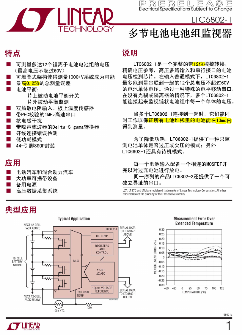
Measurement Error Over
Extended Temperature
0.30
0.25
0.20
~ 0.15
a::
~ 0.10
8S 0.05
~
0
~ -0 .05
a::
~ -0 .10
«
~ -0 .15
-0 .20
-0 .25
-0 .30
- 50 - 25
.
-.'.-
~ '- -..
~ .
' .. 1;'-......
....... ~. ~...... .' -';;;
....... ..'
.... ......
;.0,,-
'"
--
25
0
TEMPERATU RE(OC)
50
75
100 125
68021P
1
• ~ ~~Ij ~ ~ it121'i' ~ T ~)tf? ~)tf?~fl s~ ~lli
( ~ ~ ~lli=1'~J160V )
~±t~~~*~f~{~~~lj~1ooo+v*~1Cp)(;~ ~~m
~~O. 25%S~/~,~~lj~i~~
~)tf?~fJj:
•
•
•
J=t ...tfffi:ij] ~)tf?~fJj7f~
J=t ~Hffi:ij] ~fJj llil~~lj
• ~~~~ffl~A,~...t~~~~~
•
•
•
•
•
•
*PEC*~~~S~1 MHz~~$ [J
:tj[ ~MFFtJt
*P*Fi;~;&: ~ S~De Ita-S i gama~~t!k:~
*~~~t~i~i~*fi~~lj
1~!JJ~f*~~
44-~IMnssoPH~
@Jf]
•
•
•
•
~ij]5~$~Qm~ij] 1J 5~$
*!JJ$~t~*i9:ti
tim ~;m
~lli~'9:tm*~*~1C
Typical Application
NEXT 12-CELL
PACK ABOVE
V'
MUX
12-BIT
"'LADC
NEXT 12-CELL
PACK BELOW
V-
EXTERNAL L...----,-_---l
TEM P
68021TAOla
SERIAL DATA
TOLTC6802-1
BELOW
100k NTC
100k
�
LTC6802-1
(Note 1)
Total Supply Voltage (V+ to V-)
Input Voltage (Relative to V-)
C1
C12
Sn pins
CSBO, SCKO, SDOI
All other pins
Voltage Between Inputs
Cn to Cn-1
Input Current
All Pins
Operating Temperature Range
Specified Temperature Range
Junction Temperature
Storage Temperature Range
*n =2to 11
60V
-O.7V to 9V
V+ - O.7V to V+ + O.7V
Cn-1 - O.7V to Cn-1 +9V
V+ -1.4V to V+ + O.7V
-O.7V to 7V
-O.7V to 9V
±1OmA
-40°C to 85°C
-40°C to 85°C
150°C
-65°C to 150°C
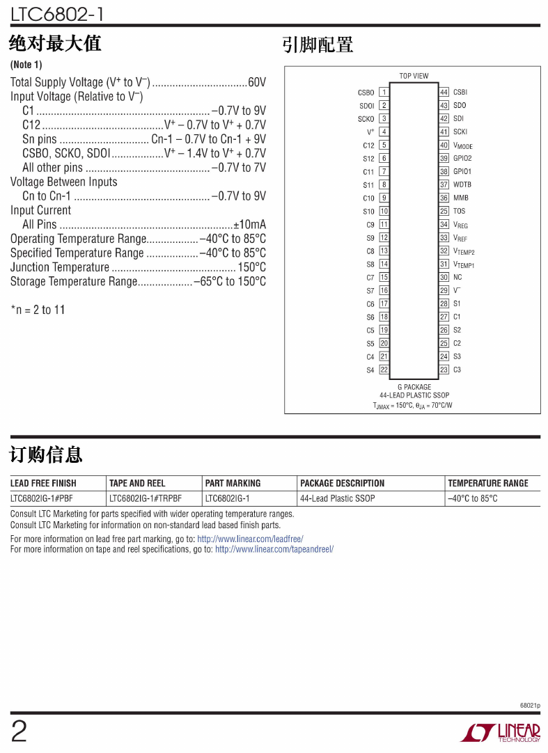
TOP VIEW
CSBI
SOO
SOl
SCKI
CSBO
SOOI
SCKO 3
V+
C12
S12
C11
S11
C10
S10
C9
S9
C8
S8
C7 15
S7
C6
S6
C5
S5
C4
S4
G PACKAGE
44-LEAO PLASTIC SSOP
TJMAX= 150°C, 8JA = 70°CIW
TAPE AND REEl
LTC68021G-1 #TRPBF
LEAD FREE FINISH
LTC68021G-1 #PBF
Consult LTC Marketing for parts specified with wider operating temperature ranges.
Consult LTC Marketing for information on non-standard lead based finish parts.
For more information on lead free part marking, go to: http://www.linea[com/leadfree/
For more information on tape and reel specifications, go to: http://www.linea[com/tapeandreel/
PART MARKING
LTC68021G-1
PACKAGE DESCRIPTION
44-Lead Plastic SSOP
2
TEMPERATURE RANGE
-40°C to 85°C
68021p
�
LTC6802-1
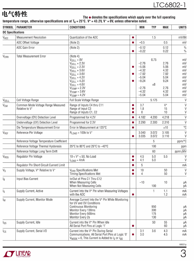
The . denotes the specifications which apply over the full operating
temperature range, otherwise specifications are at TA = 25°C. V+ = 43.2V, V- = OV, unless otherwise noted.
SYMBOL I PARAMETER
DC Specifications
VACC
I CONDITIONS
Measurement Resolution
ADC Offset Voltage
ADC Gain Error
Ouantization ofthe ADC
(Note 2)
(Note 2)
I-M-IN------
MAX I
TYP
(Note 4)
VCELL =OV
VCELL =2.3V
VCELL =2.3V
VCELL =3.6V
VCELL =3.6V
VCELL =4.2V
VCELL =4.2V
VCELL =4.6V
VTEMP =2.3V
VTEMP =3.6V
VTEMP =4.2V
Full Scale Voltage Range
Range of Inputs C4 thru C11
Range of Input C3
Range of Inputs C1 , C2
Programmed for4.2V
Programmed for 2.3V
Error in Measurement at125°C
RLOAD =1OOk to V-
25°C to 85°C and 25°C to-40°C
10< V+ < 50, No load
ILOAD =4mA
VERR Specifications Met
Timing Specifications Met
In/Out of Pins C1 Thru C12
When Measuring Cells
When Not Measuring Cells
Current Into the V+ Pin when Measuring Voltages
with the ADC
Average Current Into the V+ Pin While Monitoring
for UV and OV Conditions
Continuous Monitoring
Monitor Every 130ms
Monitor Every 500ms
Monitor Every 2s
Current into the V+ Pin When Idle
All Serial Port Pins atlogic '1'
Current into the V+ Pin During Serial
•
Communications. All Serial Port Pins at logic '0' •
VMODE =0, This Current isAdded to Isor las
VERR
Total Measurement Error
VCELL
VCM
Cell Voltage Range
Common Mode Voltage Range Measured
Relative to V-
Overvoltage (OV) Detection level
Undervoltage (UV) Detection level
Die Temperature Measurement Error
Reference Pin Voltage
Reference Voltage Temperature Coefficient
Reference Voltage Thermal Hysteresis
Reference Voltage long Term Drift
Regulator Pin Voltage
Regulator Pin Short Circuit Current limit
Supply Voltage, V+ Relative to V-
Input Bias Current
Supply Current, Active
Supply Current, Monitor Mode
Supply Current, Idle
Supply Current, Serial I/O
VREF
VREG
Vs
18
Is
1M
las
lcs
•
• -0.5
• -0.22
-0.12
-2.76
-4.32
• -5.06
• -7.92
• -9.24
-5.04
-2.76
-4.32
-5.04
0
3.7
•
• 1.8
•
• 4.182
• 2.290
•
• 3.035
3.040
4.5
•
• 4.1
•
•
•
5
10
4
-10
•
3.1
3.0
1.5
0.75
±8
5.175
4.200
2.300
3.072
3.072
5
100
60
5.0
5.0
100
1
950
300
175
130
50
3.6
0.5
0.12
0.22
2.76
5.06
4.32
7.92
5.04
9.24
2.76
4.32
5.04
V+
15
10
4.218
2.310
±10
3.105
3.110
5.5
50
50
10
1.1
1.2
55
60
4.3
4.5
UNITS
_
mViBit
mV
%
%
mV
mV
mV
mV
mV
mV
mV
mV
mV
mV
mV
V
V
V
V
V
V
°C
V
V
ppmrc
ppm
ppm/y'khr
V
V
mA
V
V
~A
pA
mA
mA
~A
~A
~A
~A
~A
~A
mA
mA
68021 P
3
�
LTC6802-1
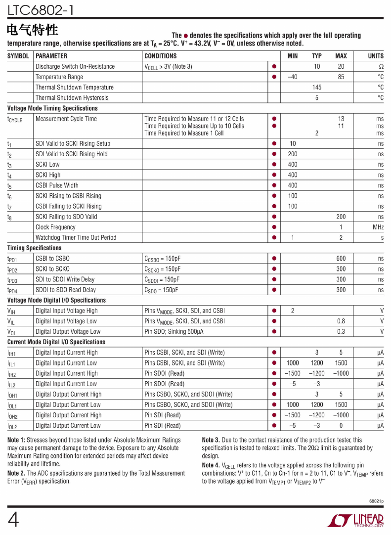
temperature range, otherwise specifications are at TA =25°C. V+ =43.2V, V-=OV, unless otherwise noted.
SYMBOL
MIN
The . denotes the specifications which apply over the full operating
•
• -40
PARAMETER
Discharge Switch On-Resistance
Temperature Range
Thermal Shutdown Temperature
Thermal Shutdown Hysteresis
CONOITIONS
VCELL> 3V (Note 3)
Voltage Mode Timing Specifications
Measurement Cycle Time
tCYCLE
t1
t2
t3
t4
t5
t6
t7
t8
SOl Valid to SCKI Rising Setup
SOl Valid to SCKI Rising Hold
SCKllow
SCKI High
CSBI Pulse Width
SCKI Rising to CSBI Rising
CSBI Falling to SCKI Rising
SCKI Falling to SOO Valid
Clock Frequency
Watchdog Timer Time Out Period
Digital Input Voltage High
Digital Input Voltage Low
Digital Output Voltage Low
CSBI to CSBO
SCKI to SCKO
SOl to SOOI Write Delay
SOOI to SOO Read Delay
Timing Specifications
tpD1
tpD2
tpD3
tpD4
Voltage Mode Digital I/O Specifications
VIH
VIL
VOL
Current Mode Digital I/O Specifications
IIH1
IIL1
IIH2
IIL2
IOH1
IOL1
IOH2
IOL2
Digital Input Current High
Digital Input Current Low
Digital Input Current High
Digital Input Current Low
Digital Output Current High
Digital Output Current Low
Digital Output Current High
Digital Output Current Low
Time Required to Measure 11 or 12Cells
Time Required to Measure Up to 10Cells
Time Required to Measure 1 Cell
CCSSO =150pF
CSCKO =150pF
CSDOI =150pF
CSDO =150pF
Pins VMODE, SCKI, SOl, and CSBI
Pins VMODE, SCKI, SOl, and CSBI
Pin SOO; Sinking 500~A
Pins CSBI, SCKI, and SOl (Write)
Pins CSBI , SCKI , and SOl (Write)
Pin SOOI (Read)
Pin SOOI (Read)
Pins CSBO, SCKO, and SOOI (Write)
Pins CSBO, SCKO, and SOOI (Write)
Pin SOl (Read)
Pin SOl (Read)
1
10
200
400
400
100
100
•
•
•
•
•
• 400
•
•
•
•
•
•
•
•
•
•
•
•
•
•
• 1000
• -1500
• -5
•
• 1000
• -1500
• -5
2
TYP
10
145
5
2
MAX
20
85
13
11
200
1
2
600
300
300
300
0.8
0.3
3
1200
-1200
-3
3
1200
-1200
-3
5
1500
-1000
5
1500
-1000
0
UNITS
Q
°C
°C
°C
ms
ms
ms
ns
ns
ns
ns
ns
ns
ns
ns
MHz
s
ns
ns
ns
ns
V
V
V
~A
~A
~A
~A
~A
~A
~A
~A
Note1: Stresses beyond those listed under Absolute Maximum Ratings
may cause permanent damage to the device. Exposure to any Absolute
Maximum Rating condition for extended periods may affect device
reliability and lifetime.
Note 2. The AOC specifications are guaranteed by the Total Measurement
Error (VERR) specification.
Note 3. Due to the contact resistance ofthe production tester, this
specification istested to relaxed limits. The 20Q limitis guaranteed by
design.
Note 4. VCELL refers to the voltage applied across the following pin
combinations: V+ to C11, Cn to Cn-1 for n =2to 11 , C1 to V-. VTEMP refers
to the voltage applied from VTEMP1 orVTEMP2 to V-
68021p
4
�
SDOI (Pin 2): $1T~1J.Hi A/ti ttl s IJ]!p 0 :tEf~ EfJ iJ IMP29f§ji 0
CSBO (Pin 1): )=f~tittl (11£~~1H<)() 0
CSBO~)=f~1*%tiACSBIB~~tlft 0 :tEf~AJI'f-MJ
9=l, CSBOflFf!JIRi;ffr~~J1t)=f 0 ~Yt!."1! fIH#. ~
" 9=l B~" $ Ll "$ ?1- 0
AJI'f-MJ 9=l, SDI0 flFfJAl:~~J1t)=f 1§(~~m .!JX;
~~{~J!~r ~~J1t)=f 0 ~Yt!."1!fIH#.~ "9=l B~ "$
o "$ ?1- 0
SCKO (Pin 3): $1TSt'fJfttittl 0 SCKO~$1T
st'fJfttiASCKI B~~tIft 0 :tEf~AJI'f-MJ 9=l SCKOmT
!JIRi9Jr~~J1t)=f 0 ~Yt!."1!ml#.~ "9=lB~ "$ 0 "$
?1-
LTC6802-1
V- (Pin 29) :1tffl9=l®!~lItiJI~~~rmm9=l1¥J
ii11£ ~~\4§ ji 0
NC (Pin 30) :30iJ IRtP :(£ ~E.: )=f I*J Wi&.rl - -1' 1 0~
mEfJ ~ ~il)=j V-f§ji o
li:~ iJ I MP pJ K 2 9X ~PCB fRI
Vtemp l . Vtemp2 (Pins 31 ,32) :1ffilt)jH~ w~~ trHtr
A iJ IMP 0 ADC(t~B& ~·tJ~ ~~) 1~U :!l iJ IMPVtempxf§xi
-=f iJ IMPV-EfJ ~ ffi {~jf~~ m *{~H¥ :(£TMP * 1J ~~ ~
o ADC EfJ 1~U :!I~ f§xi-=fVREFiJ IMP EfJ ~ ffiill1 T EfJ ,
~ ~ - -1'oo. EfJ~~~m~~m EfJ m ~.ji~ ~
VREFiJ IMPI ~ m t!Q1ffilt)jt 0 VTEMPtrHtrA illpJ3 1itt
~- -1'i&.ffl EfJADCtrHtrA 0 13:{PJf§xi-=fV-mIE:(£
OV~5.125V Z 1'8] EfJ ~ ffi:l!.8WJ ·*Bl1~U :!I 0
V+ (Pin 4) ::tE1!m 9=l, Tffl~~Pin 4~ ~rmit*i
B~~~~{f[:i!1§(, ~'Hf'H"1JLr, V+~C12~~;fB
rnJ
VREF (Pin 33) : 3.075V ~ ffi ~ ~ trHtr t±:l 0 li:~ iJ I
RtP rm ~ffl 11lFEfJ ~ ~ ~ £~ 0 li:~ iJ IRtP pJ IJlR ~JJ ji~ fUv
iJ IMPIEfJ 100K~£l{l1l jr W ~ $Jt o ]'!:AEfJ~$Jt~Q * ~
C12,C11 ,C1 0,C9,C8,C7,C6,C5,C4,C3,C2,C1(Pin ji~3W li:~iJ IMPI rm~ ffl:iEJJJ:LT6003 E!JG~ 1!;J,-W ~ill
s 5,7,9,11,13,15,17,19,21,23,25,27):C1¥tlC12~
JKi7j!~ ~rmJ'j!~ ~ffB~tiAtIfii 0
1T ~{rf 0
VREG (Pin 34) : ~~H1 ~~ffi ~~ trHtr t±:l 0 li:~ iJ IMPrm
li:~ iJ IMPpJ/'gjrW:fh$Jt:ttHJt
li:~ iJI MP::f ~t±:l J~ ~ ~1E &rPJ ~ ~1E o
~ )=fLTC6802-1J1t)=f~~PJJKi7~~ 12~~rmJ'j!
~ o :tE~rmxtit*i9=l, ~11£~~~V-sIJ]!p;fB:i!,
r~~~11£~~~r~~J1t)=fB~C1slJ]!p;fB:i!,
:!nUrtt:l:j[ o gllri1~J1t)=f
~ ffl 1 IlF EfJ ~ ~ ~ £~ o
4mA ~ ~1E o
TOS (Pin 35) : 11H~rmWtrHtrA (Top ofStack
Input ) 0 3 LTC6 8 02- 1~ 11H~ ~~ rm W EfJ~: )=f ut
;l'I;{lliLTC6802-1EfJ
, rm~ ~~ TO S~VREGf§ 3{f ,
S12,Sl1,S10,S9,S8,S7,S6,S5,S4,S3,S2,Sl (Pins
Tos iJIRtP ~V- iJI MM§ ji o 3 TO S~ VREGf§ ji Ut ,
6,8,10,12,14,16,18,20,22,24,26,28):S1¥tlS12mT SDIOiJ IMP EfJtrHtrA~~*BlLTC 6 8 02 - 1 ,m~ 0 3 TO S~
~~~rm ~ff o ~ ~rmg£l9=l B~jft~~rmJ'j!~ttl:OO V-f§3{fUt, LTC6802-1 ~1V EESDIOiJ IRtP1'ti2iEfJ ~
J1ffst, SslJ]!p~~m~xt]!~~rmJ'j!~Jjt~o 4JJ Wi o
~S s IJ]!p pg $*13~~mT Jit~ B~N¥Z;JMOSFET
o ~Yt!."~-MJI!J "0 NMOS pg$~lltJLPJJt¥tl20gx~fH:
, :tE~~1!m9=l@H!mj~$~~1l~itfkNMOSIEI
Jjt~Wf=~B~1A!lL ~1!mpg$MOSFETxt~rm
J'j!~*fiJit~M,m~~J1t)=fpg$m~*fiJKi.
o ~Yt!."1!ml#.~ "9=l B~ ":rJJ$,fflit~1~~*ffl"0
) 0 3 MMB )tt-=f {[£ ~ Sf Bt ( ~ V-~~\4§1I'lJ)
LTC6802-1 illA m t!Qt~ ):t o ~ }M"{~ ffliJ?~ "~ "I
fF t~ ):t " 0
MMB (Pin 36) :mt!QtJt rttrHtrA ({[£ ~Sf ilf ~~
,
Ss IJ]!p-tfL;fB ~T~~~ll {Il ~ 1OkB~ pg $l:f}L
~~1l, lEIlEtS slJ]!pPJ mT!JIRi9Jj~$MOSFETB~ ri
~~ ~~1f£s1i B~Jjt ~'I~Hj~ 0
WDTB (Pin 37) : ~TJ ~fTI itut ~~trHtr t±:l iJ IMP ({[£
~Sfilf ~~) 0 3 SCKI iJ I MP ji~~2 st~ ilf &m ut ,
WDTBtrHtr t±:l ilf~~ 0 WDTB ~- -1'7f£~ 1~ tRNM0 strHtr
li:~ iJ IMPtrHtr t±:l{[£ ~Sf~V-3f~
t±:l 0 3 iJ IMPilf~~ Bt ,
{:\ILTC6802-1 EfJjiJjc Ji * 1J~~ o ~TJ ~fTIitut~~ EfJJ}] ~~
WJ·i&.rl~~jiJjc K * 1J~~ ~ EfJWTDEN{ :\I K ~ ~I:.tJ 0 ~
}M"1~ ffl iJ? ~ "~ EfJ "~ n~fTI ~£~" 0
68021P
5
�
LTC6802-1
srW:t:JJM
ttl 0
GPI01,GPI02(Pins 38,39): ]IJtH1ltrA/~1ltr
litSIJ]!pB~1!ffl*fR-TMMBSIJ]!pB~~~ o
~MMBslJ]!p~1Wi ~-¥8-t, litslJ]!p1t~it]lB~
GPIOslJ]!p1!ffl 0 ~GPIOWCi[~ff~1fL~A "0"
PIittffl7f j§~~1H1ltr ttl,
IItJ 8-tlitsl J]!p ~-¥~~~V -;fB
lItJ o ~GPIOWCi[~ff~1fL~A "I" PI~~litslJ]!p
~-T1Wi~1l~, lit8-tffij~~~j~$~~1l~~litslJ]!p~
VREG;fB.i! 0
]IJ1i~*WCi[~ff~9=J B~GPIO 1,GPI0 21fL ,
PI9almlitslJ]!pB~I1t~~ o 1~Hm, ~ "0" fJt~A
GPIO l1fL8-t, 1EI~~1ltrttlNMOSFET~~slJ]!p38~-¥
i~*B~ili.IID{H~~Jg,~ "0" ; ~
f1L~!fOV-;fBIItJ,
"I" fJt~AGPI0l1fL8-t, litslJ]!p1t~IWi~ll~,
i~*B~ili.IID{H~ "0" ili~ "I" *fR-TSIJ]!p38B~
~lW~ffo GPIOsslJ]!pPI*ffl~7fgLTC6802-1
)1'fJ IEB~ ~j§, ~i~*LTC6802-1)1'fJ IE ~j§B~J!~J1:
{Ho
~MMBslJ]!p~11£8-t, GPIOslJ]!p!fOWDTBSIJ]!p
fJt1t~ 1ifftIEJKi?~ ~ri!! ~ B~ ~1ltrA sl J]!p1!ffl 0 ~Yt!. "
1!ffll5t~" 9=J B~ "JKi?~flA:" 0
VMODE (Pin 40): ~ffflA:~1ltrA o ~
VMODE!fOVREG;fB.i!8-t, SCKI,SDI,SDO!fO
CSBISIJ]!pWCi[~ ~ff~1ltrA~1ltrttl slJ]!p1!ffl 0 ]!g~
]!]!®slJ]!p~~riJE;f1~i1ETTLJ!~J1:~-¥o ~
LTC6802-1 *-Tf;i!A:~l'ftlJ~ r!Ilfij8-tffij~~~
VM0 DE!fOVREG;fB.i! 0
~VMODE!fOV-;fB.i!8-t, SCKI,SDI!fOCSBISI
J]!pWCi[~ ~mE~1ltrA~1ltrttl slJ]!p1!ffl, SDO~1!ffl 0
~LTC6802-1*-T~*-Tf;i!A:~l'ftlJ~r!Ilfij (fJt~
~~LTC6802-1!Jgi9J) 8-tffij~~~VMODE!fOV-;fB
.i!o
SCKI (Pin 41):$fr8-t$Jft~1ltrA o ~
VM0 DE!fOVREG;fB.i!8-t,
litsl J]!p~ 1=£gJ!~J1:
1'1 (TTL~-¥) ;fB.i!o ~VMODE!fOV-;fB.i!8-t
, SCKISIJ]!p~'@ffJt~~~LTC6802-1 B~
SCKOslJ]!p!Jgi9J 0 ~Yt!. "1!ffll5t~" 9=J B~ "$
/J" 0
SDI (Pin 42): $1T~fJ.H1ltrA o ~VMODE
!fOVREG;fB.i!8-t,
litsl J]!p~1=£gJ!~J1:1'1 (TTL
~-¥) ;fB.i!o ~VMODE!fOV-;fB.i!8-t, SDISI
J]!p~'@ffJt~~~LTC6802-1 B~SDIOslJ]!p!Jgi9J
o ~Yt!. "1!ffll5t~" 9=JB~ "$/J" 0
SDO (Pin 43): $1T~fJ.H1ltrttl 0 ~
VMODE!fOVREG;fB.i!8-t,
litSIJ]!p~NMOS7f
j§~~J1~1ltrttl 0 ~VMODE!fOV-;fB.i!8-t, litslJ]!p
~~ffl o ~Yt!."~ffl~~"9=J~"$/J" o
CSBI (Pin 44):)=f~~1ltrA (11£~-¥1J~~)
o ~VMODE!fOVREG;fB.i!8-t, litslJ]!p~1=£g
J!~J1:1'1 (TTL~-¥) ;fB.i!o ~VMODE!fOV-;fB
.i!8-t, CSBISIJ]!p~'@ffJt~~~LTC6802-1 B~
CSBOslJ]!p!Jgi9J 0 ~Yt!. "1!ffll5t~" 9=J B~ "$
/J" 0
6
68021P
�
LTC6802 1
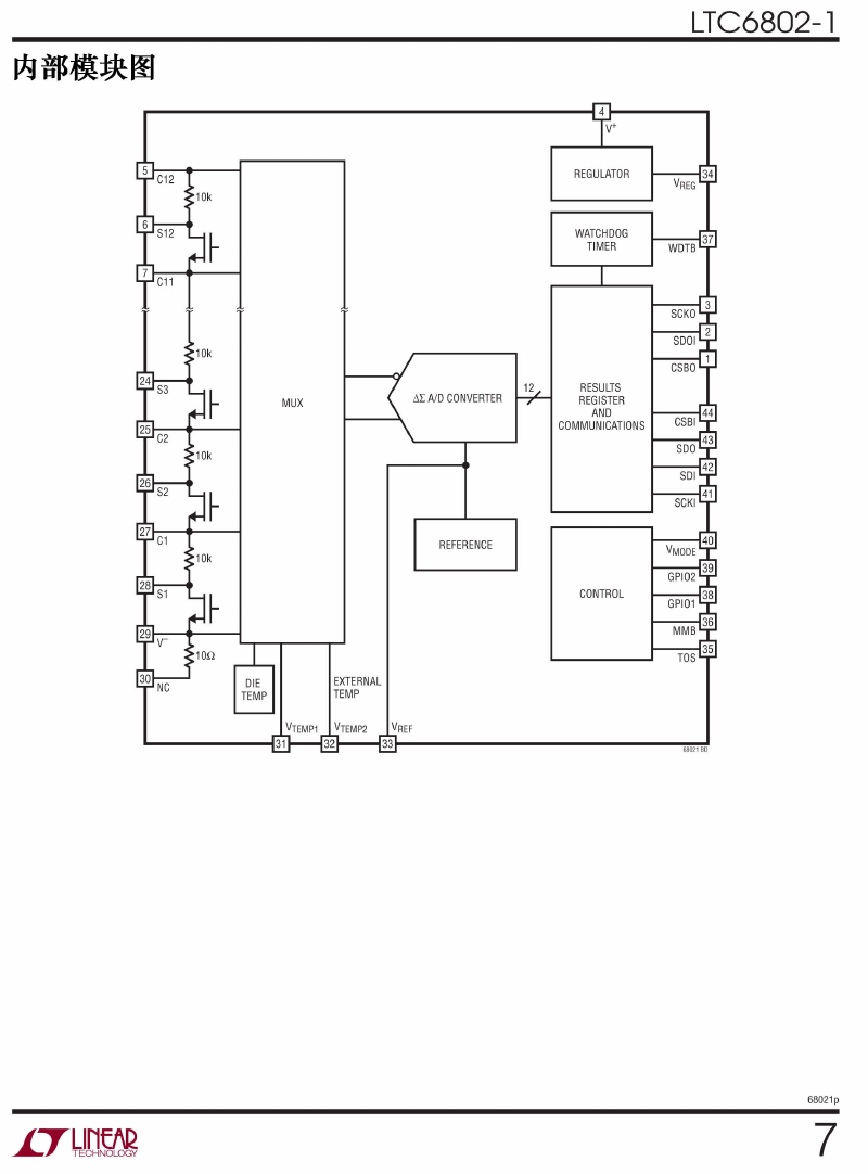
REGULATOR
WATCHDOG
TIMER
10k
MUX
~l: AIDCONVERTER
12
RESULTS
REGISTER
AN D
COMMUN ICATIONS
REFERENCE
CONTROL
DIE
TEMP
EXTERNAL
TEMP
68021 60
68021P
7
�
LTC6802-1
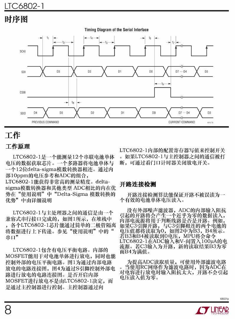
SCKI
CSBI
Timing Diagram of the Serial Interface
03
02
01
SOO
04
03
02
01
00
07:."04 E
PREVIOUSCOMMANO
CU RRENT COMMANO
6915TO
LTC6802-11AJ $ B


 2023年江西萍乡中考道德与法治真题及答案.doc
 2012年重庆南川中考生物真题及答案.doc
 2013年江西师范大学地理学综合及文艺理论基础考研真题.doc
 2020年四川甘孜小升初语文真题及答案I卷.doc
 2020年注册岩土工程师专业基础考试真题及答案.doc
 2023-2024学年福建省厦门市九年级上学期数学月考试题及答案.doc
 2021-2022学年辽宁省沈阳市大东区九年级上学期语文期末试题及答案.doc
 2022-2023学年北京东城区初三第一学期物理期末试卷及答案.doc
 2018上半年江西教师资格初中地理学科知识与教学能力真题及答案.doc
 2012年河北国家公务员申论考试真题及答案-省级.doc
 2020-2021学年江苏省扬州市江都区邵樊片九年级上学期数学第一次质量检测试题及答案.doc
 2022下半年黑龙江教师资格证中学综合素质真题及答案.doc