使用计算整定PI参数的方法
1 PI Controller Design
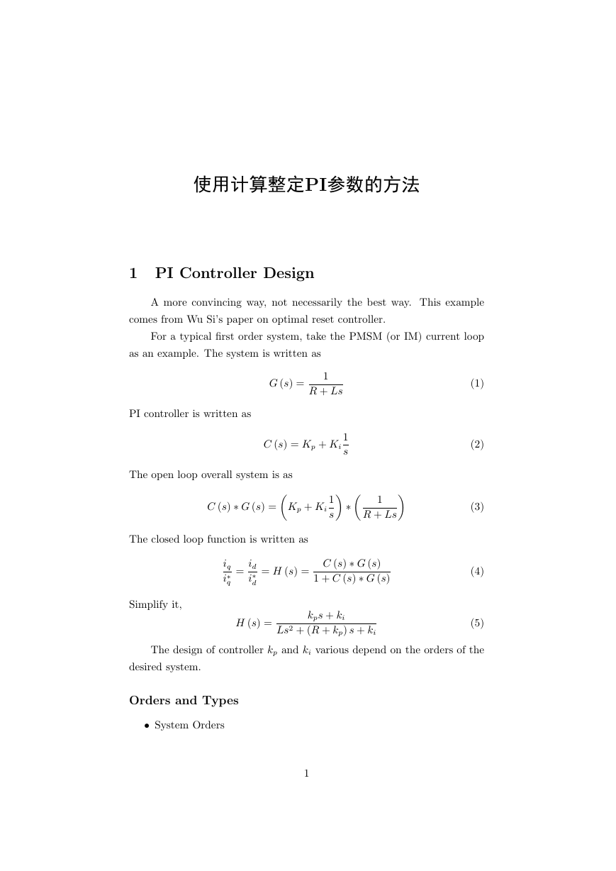
A more convincing way, not necessarily the best way. This example
comes from Wu Si’s paper on optimal reset controller.
For a typical first order system, take the PMSM (or IM) current loop
as an example. The system is written as
PI controller is written as
G (s) =
1
R + Ls
C (s) = Kp + Ki
1
s
The open loop overall system is as
∗
1
s
1
R + Ls
C (s) ∗ G (s) =
Kp + Ki
The closed loop function is written as
Simplify it,
iq
i∗
q
=
id
i∗
d
= H (s) =
C (s) ∗ G (s)
1 + C (s) ∗ G (s)
H (s) =
kps + ki
Ls2 + (R + kp) s + ki
(1)
(2)
(3)
(4)
(5)
The design of controller kp and ki various depend on the orders of the
desired system.
Orders and Types
• System Orders
1
�
The order of the system is defined by the number of independent
energy storage elements in the system, and intuitively by the highest
order of the linear differential equation that describes the system. In
another word, the highest exponent in the denominator.
• System Types
The system type is defined as the number of pure integrators in the
forward path of a unity-feedback system. That is, the system type
is equal to the value of n when the system is represented as in the
following figure. It does not matter if the integrator are part of the
controller or the plant.
First order system
This section is based on a milestone report. There is a paper that can
be taken as reference.
Telford D, Dunnigan M W, Williams B W. Online identification of
induction machine electrical parameters for vector control loop tuning. In-
dustrial Electronics, IEEE Transactions on, 2003, 50(2): 253-261.
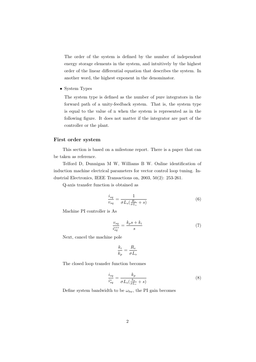
Q-axis transfer function is obtained as
isq
vsq
=
1
σLs( Rs
σLs
+ s)
Machine PI controller is As
vsq
ierr
sq
=
kps + ki
s
Next, cancel the machine pole
ki
kp
=
Rs
σLs
The closed loop transfer function becomes
isq
i∗
sq
=
kp
σLs( kp
σLs
+ s)
Define system bandwidth to be ωbw, the PI gain becomes
(6)
(7)
(8)
2
�
图 1: damping ratio
kp = σLsωbw
ki = Rsωbw
(9)
Second order system
The ideal characteristic equation of the closed loop control system
should be
D (s) = s2 + 2ξωns + ω2
n
For a given ξ and ωn, the kp and ki value can be found as
kp = 2ξωnL − R
ki = ω2
nL
(10)
(11)
(12)
Next step is to decide the value of ξ and ωn.
ξ is the damping ratio, the value is undamped (ξ = 0), underdamped
(ξ < 1) through critically damped (ξ = 1) to overdamped (ξ > 1). System
response is like Figure 1.
ωn here is the undamped natural frequency. The value of ωn will decide
the system bandwidth. Generally speaking the larger the system bandwidth
is, the faster the system responses. Also, as the Gain for signal with higher
frequency is very small, it can be considered that those signal are filtered.
3
�
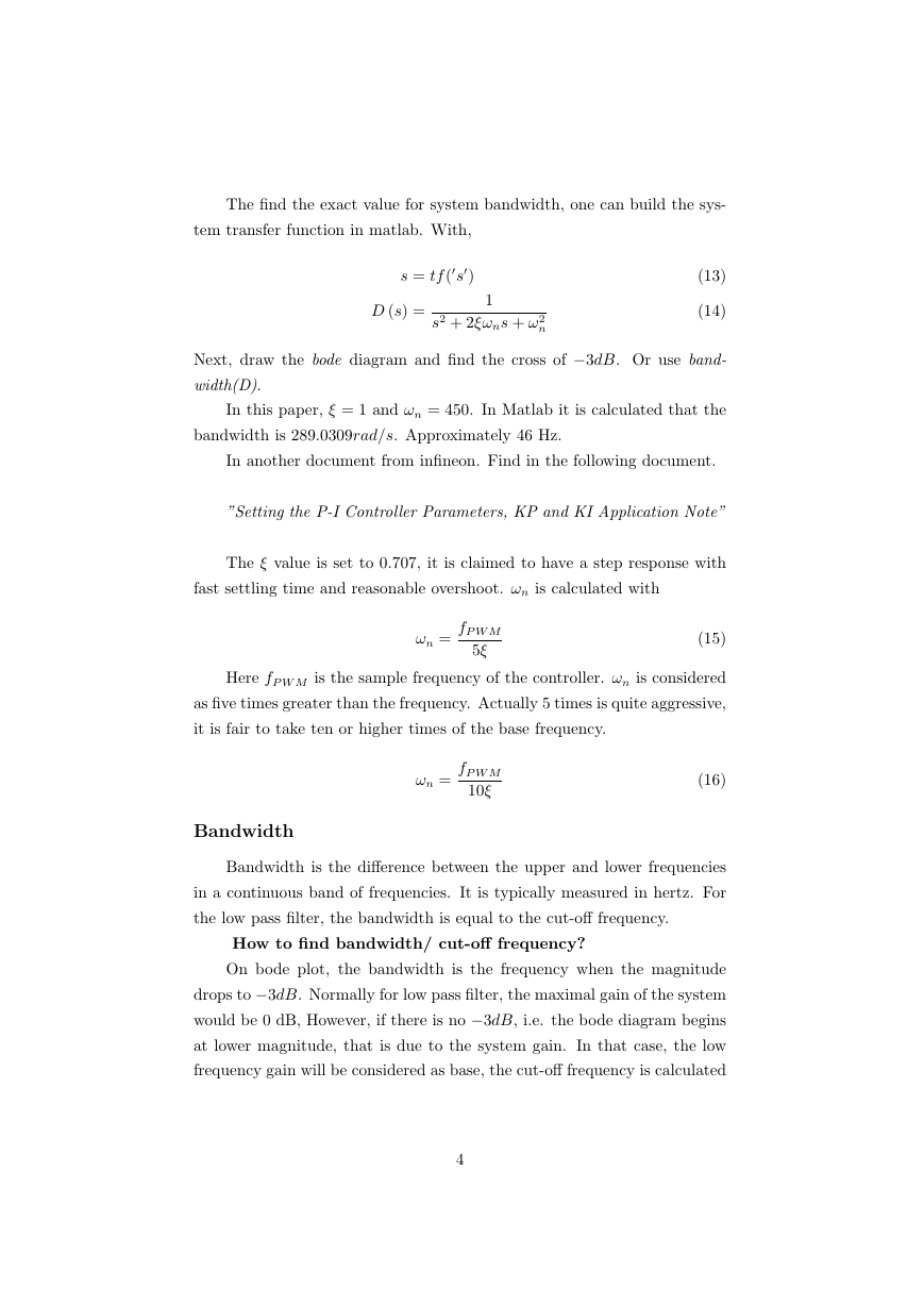
The find the exact value for system bandwidth, one can build the sys-
tem transfer function in matlab. With,
s = tf (s)
D (s) =
1
s2 + 2ξωns + ω2
n
(13)
(14)
Next, draw the bode diagram and find the cross of −3dB. Or use band-
width(D).
In this paper, ξ = 1 and ωn = 450. In Matlab it is calculated that the
bandwidth is 289.0309rad/s. Approximately 46 Hz.
In another document from infineon. Find in the following document.
”Setting the P-I Controller Parameters, KP and KI Application Note”
The ξ value is set to 0.707, it is claimed to have a step response with
fast settling time and reasonable overshoot. ωn is calculated with
ωn =
fP W M
5ξ
(15)
Here fP W M is the sample frequency of the controller. ωn is considered
as five times greater than the frequency. Actually 5 times is quite aggressive,
it is fair to take ten or higher times of the base frequency.
ωn =
fP W M
10ξ
(16)
Bandwidth
Bandwidth is the difference between the upper and lower frequencies
in a continuous band of frequencies. It is typically measured in hertz. For
the low pass filter, the bandwidth is equal to the cut-off frequency.
How to find bandwidth/ cut-off frequency?
On bode plot, the bandwidth is the frequency when the magnitude
drops to −3dB. Normally for low pass filter, the maximal gain of the system
would be 0 dB, However, if there is no −3dB, i.e. the bode diagram begins
at lower magnitude, that is due to the system gain. In that case, the low
frequency gain will be considered as base, the cut-off frequency is calculated
4
�
as
.
cut − of f f requency = base gain − 3dB
Why 3 dB?
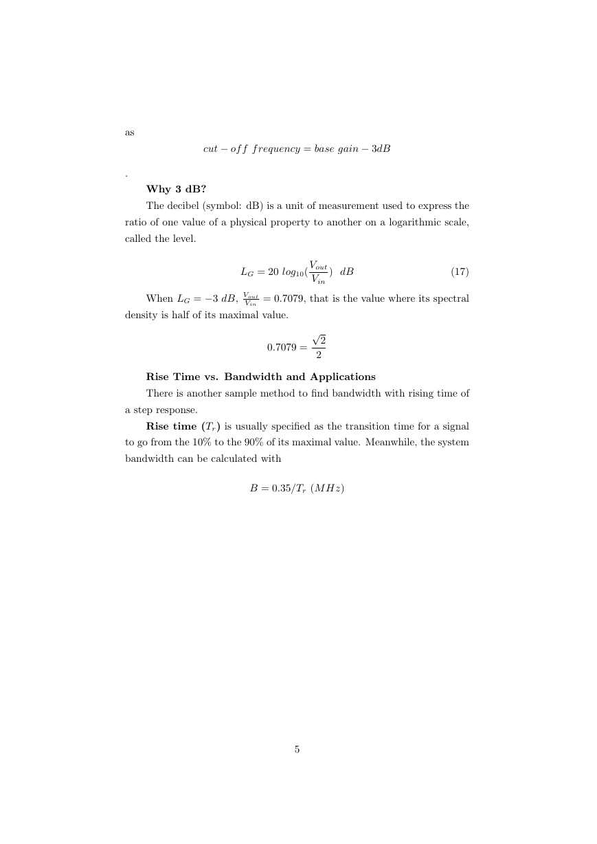
The decibel (symbol: dB) is a unit of measurement used to express the
ratio of one value of a physical property to another on a logarithmic scale,
called the level.
LG = 20 log10(
Vout
Vin
) dB
(17)
When LG = −3 dB, Vout
Vin
= 0.7079, that is the value where its spectral
density is half of its maximal value.
0.7079 =
√
2
2
Rise Time vs. Bandwidth and Applications
There is another sample method to find bandwidth with rising time of
a step response.
Rise time (Tr) is usually specified as the transition time for a signal
to go from the 10% to the 90% of its maximal value. Meanwhile, the system
bandwidth can be calculated with
B = 0.35/Tr (M Hz)
5
�


 2023年江西萍乡中考道德与法治真题及答案.doc
 2012年重庆南川中考生物真题及答案.doc
 2013年江西师范大学地理学综合及文艺理论基础考研真题.doc
 2020年四川甘孜小升初语文真题及答案I卷.doc
 2020年注册岩土工程师专业基础考试真题及答案.doc
 2023-2024学年福建省厦门市九年级上学期数学月考试题及答案.doc
 2021-2022学年辽宁省沈阳市大东区九年级上学期语文期末试题及答案.doc
 2022-2023学年北京东城区初三第一学期物理期末试卷及答案.doc
 2018上半年江西教师资格初中地理学科知识与教学能力真题及答案.doc
 2012年河北国家公务员申论考试真题及答案-省级.doc
 2020-2021学年江苏省扬州市江都区邵樊片九年级上学期数学第一次质量检测试题及答案.doc
 2022下半年黑龙江教师资格证中学综合素质真题及答案.doc