This article has been accepted for publication in a future issue of this journal, but has not been fully edited. Content may change prior to final publication. Citation information: DOI 10.1109/JSEN.2018.2857502, IEEE Sensors
Journal
JOURNAL OF XXXX, VOL. XX, NO. XX, MMMM 2018
1
Step Length Estimation Methods
based on Inertial Sensors: A Review
Luis E. D´ıez, Alfonso Bahillo, Jon Otegui and Timothy Otim
Abstract—Inertial sensors are included in most of the current
smart devices and many researchers have identified their ability
to be used for analyzing different parameters of human behavior.
Among them, the pedestrian’s step length provides very useful
information for different applications, such as pedestrian dead
reckoning positioning or gait analysis. During the last three
decades, many step length estimation methods using inertial
sensors have been proposed; however, there is no specific review
work that reflects the current state of the art. In this work,
we will conduct a systematic and complete review that covers
the whole workflow of tasks involved in the design, test and
evaluation of step length estimation methods based on inertial
sensors. The main conclusion drawn from this review is that the
lack of public datasets and standard methodologies to guide the
testing and evaluation makes it difficult to compare the different
methods in a fair and robust way. Some reflections on how to
move forward on this direction have been presented.
Index Terms—Step Length Estimation, Walking Speed Estima-
tion, Inertial Sensor, Pedestrian Dead Reckoning, Gait Analysis
I. INTRODUCTION
T HANKS to the development of micro electro-mechanical
systems (MEMS) technology, inertial sensors have be-
come smaller, lighter and cheaper, and they are now included
in many of the current smart devices. This presents many
opportunities for measuring, detecting, estimating and classi-
fying different parameters of human behavior and locomotion.
Among them, the step length estimation (SLE) has attracted
the attention of many researchers because of the possibility of
using this information in a variety of applications, such as sport
activity monitoring, human gait analysis, energy consumption
assessment, or prediction of human health status [1].
One of the most important applications of SLE is pedestrian
positioning. On the one hand, because of the potential of this
end application and, on the other hand, because pedestrian
positioning demands the highest requirements of the SLE
methods. Let’s develop these two ideas in more detail:
• Inertial pedestrian dead reckoning (PDR) is a positioning
technique whose main strength is that no additional
Manuscript received on March 28, 2018
This work has been supported in part by the Spanish Ministry of Economy
and Competitiveness under the ESPHIA project (TIN2014-56042-JIN),
in
part by the Basque Department of Education under the BLUE project (ref.
PI 2016 0010), and in part by the Research Training Grants Programme of
the University of Deusto
L. E. D´ıez, A. Bahillo and T. Otim are with Faculty of Engineering,
University of Deusto, Av. Universidades, 24, 48007, Bilbao, Spain, e-mail:
{luis.enrique.diez, alfonso.bahillo, otim.timothy}@deusto.es.
J. Otegui is with DeustoTech-Fundaci´on Deusto, Deusto Foundation, Uni-
versity of Deusto, Av. Universidades, 24, 48007, Bilbao, Spain, e-mail:
jon.otegui@deusto.es.
infrastructure needs to be installed in the environment. It
only requires the inertial sensors (namely, accelerometers
and gyroscopes) that are carried by the pedestrian. The
strapdown inertial navigation system (INS) mechaniza-
tion is the standard implementation of inertial PDR
but, because of the significant errors of MEMS sensors,
the position error grows cubically in time. To reduce
this drift, it is posible to apply zero-velocity updates
(ZUPTs) when the foot
is stationary on the ground,
making the position error linear with the number of steps
[2][3]. However, this correction requires that the sensor
is mounted on the foot, which may mean a limitation
of usability. A step-and-heading system (SHS) is an
alternative method of implementing a PDR system and
it is based on the integration of the displacement vectors
associated to each step. For obtaining those displacement
vectors, a SHS is composed of three main sub-algorithms:
step detection, step length estimation (SLE), and step
heading estimation [4]. Therefore, although the step
heading estimation is currently the sub-algorithm whose
performance is the most limiting for positioning purposes,
the SLE is also one of the basic parts. One advantage of
the SHS implementation is that its position error is also
proportional to the number of steps (similar to the INS
with ZUPT implementation) but without the restriction
of using only foot-mounted sensors. Therefore, SHS, and
SLE methods as one of its main parts, are essential for
the development of pedestrian positioning systems that
are based on wearable devices, which are considered as
key devices for implementing real and practical seamless
Location Based Services (LBS).
• The accuracy requirements for SLE methods is more
demanding for positioning purposes than for other appli-
cations. For example, a 1% estimation error after traveling
8 kilometers (i.e., 80 meters) makes little difference if
the purpose of the application is to monitor a person’s
activity level, for instance. On the contrary, that same 80
meters error could mean missing the room in which a
person is and, depending on the final LBS, this could be
unacceptable.
There are many proposals for SLE methods which are based
on different models and assumptions and which are tested and
evaluated in various ways. This indicates that SLE is still in
its research stage and that there is no existing gold standard
solution. However, in the scientific literature there are not
specific surveys that review the state of the art of this topic.
Only a few general positioning surveys [4]–[6] and new SLE
1558-1748 (c) 2018 IEEE. Personal use is permitted, but republication/redistribution requires IEEE permission. See http://www.ieee.org/publications_standards/publications/rights/index.html for more information.
�
This article has been accepted for publication in a future issue of this journal, but has not been fully edited. Content may change prior to final publication. Citation information: DOI 10.1109/JSEN.2018.2857502, IEEE Sensors
Journal
JOURNAL OF XXXX, VOL. XX, NO. XX, MMMM 2018
2
Left stride
Right step
Left step
Right stride
speed estimation methods, and they found that most of
them were oriented towards clinical experimentation and
foot-mounted inertial sensors were commonly used [14].
• Only works in which the importance of the SLE is not
reduced by the use of additional sources of information
were included, such as map matching or the fusion with
other absolute positioning technologies.
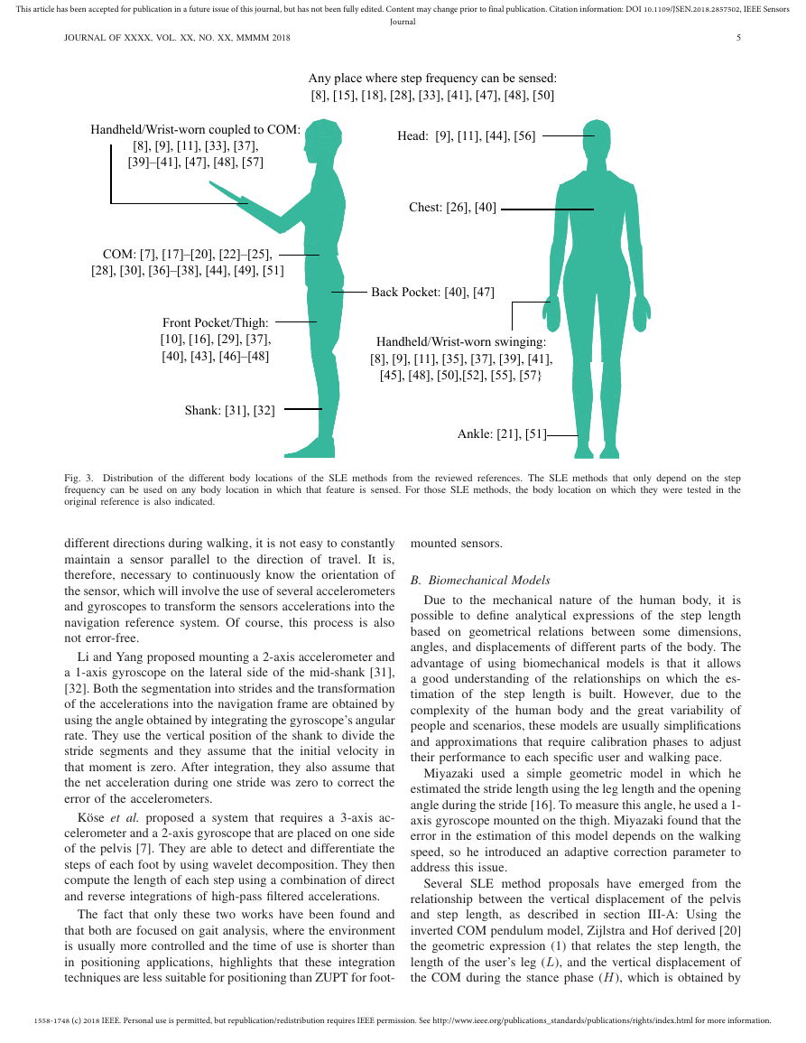
Fig. 1. Strides are defined by the positions of two consecutive footfalls of
the same foot, while the steps are defined by the positions of opposite feet.
B. Article Selection
method proposals [7]–[11] include a short and basic review.
Therefore, it would be advisable to carry out a deep and
systematic review of the SLE methods, including a description
of all of the phases of their workflow (design, implementation,
testing and validation). This would give us a complete view
of the state of the art of this field, it will identify the unsolved
problems and it will outline the future trends. This has been
both the aim and the contribution of this work.
A. Scope of the Review
To make this review tractable, the following set of criteria
were established, delimiting the scope of the review:
• The target activity is walking, although some reviewed
articles have also dealt with running.
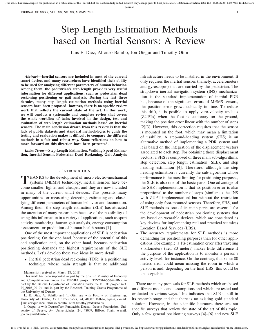
• Strides are defined by the positions of two consecutive
footfalls of the same foot, while the steps are defined by
the positions of opposite feet (see Fig. 1). When walking
straight, the stride lengths of both feet are equal to each
other and equal to the sum of the last two steps. However,
this does not happen when turning, as the foot further
from the center of rotation travels a greater distance
than the other foot. Additionally, different step length
definitions can produce different results [12]. This is
something that applications which integrate stride or step
lengths must take into account. For this review, both step
and stride length estimation methods were considered and
no further distinction has been made.
• Only works in which one sensor unit
is used were
included. Naturally, the use of multiple sensors provides
more information but it also makes the system more
complex, so it will be assumed that the user only carries
one smart device at a time.
• Works with a foot-mounted inertial sensor were not
included because it is considered that an implementation
based on INS and ZUPT is the best option when the
inertial sensor is on that body location, since no training
or calibration is needed. However, we are aware that there
exists statistical learning based SLE methods for foot-
mounted inertial sensors that obtain good results, such as
in Hannink et al. [13].
• Works that estimate the walking speed were also in-
cluded, as long as the estimation is provided at a rate
that is valid for positioning purposes. Although walking
speed estimation is quite common in gait analysis applica-
tions, they do not usually have the same requirements as
positioning. For example, Yang and Li surveyed walking
Inspired by the procedure followed by Yang and Li in
their survey [14], we searched in the following three popular
electronic engines/databases in the fields of engineering and
biomechanics: PubMed, ISI Web of Knowledge and IEEE
Xplore. The search was made on the first week of May
2018 and the searched keyword string was “(assessment OR
estimation OR calculation OR computation OR measurement)
AND (inertial sensor OR accelerometer OR gyroscope OR
inertial measurement unit) AND (speed OR velocity OR step
length OR stride velocity OR stride length) AND (walking)”
for appearance in the title (ISI Web of Knowledge) or in any
field (PubMed and IEEE Xplore). The results were then refined
by selecting only those works that were published from 1990
onwards.
Initially, 987 references were obtained. The title and the
abstract of each article was read carefully to exclude any
duplicates and works that did not fit in the defined scope.
A total of 49 works were ultimately included, as follows: [7]–
[11], [15]–[58].
C. Structure of the Review
The structure of the rest of this paper is as follows. Sec-
tion II describes the definition of the a priori questions that
we tried to answer during the literature review. The results
of the review are described in sections III, V, IV and VI.
Section VII presents a series of reflections on the availability
of standards and public datasets in this area, whose current
lack is considered to be a barrier to progress in this field.
Finally, the conclusions and some recommendations for future
work are given in section VIII.
II. DEFINING THE REVIEW QUESTIONS
To make a complete and systematic review of the state of
the art of a given field, it is advisable to identify in advance
the questions, concepts, or criteria on which the focus will be
placed when reviewing the selected literature.
In this work, to make this identification as exhaustive as
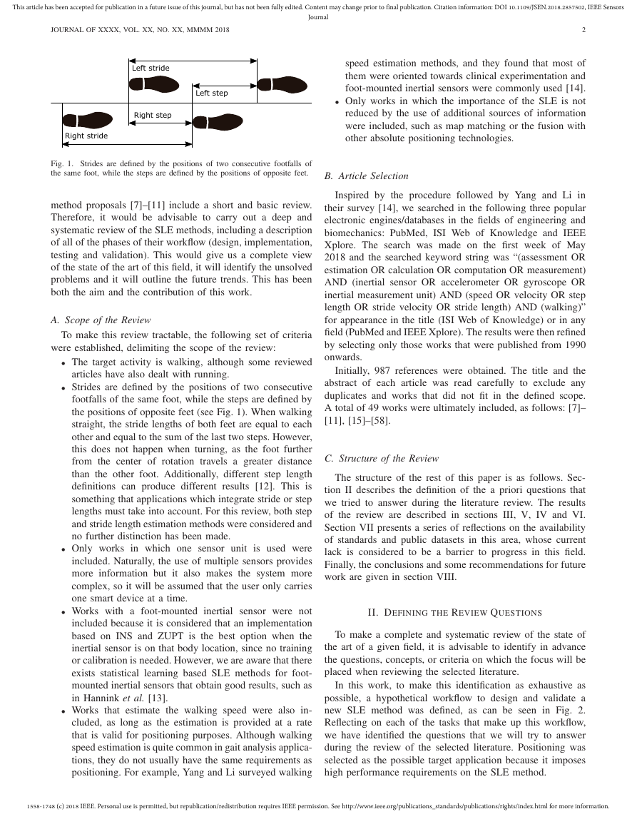
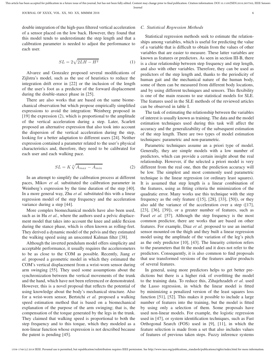
possible, a hypothetical workflow to design and validate a
new SLE method was defined, as can be seen in Fig. 2.
Reflecting on each of the tasks that make up this workflow,
we have identified the questions that we will try to answer
during the review of the selected literature. Positioning was
selected as the possible target application because it imposes
high performance requirements on the SLE method.
1558-1748 (c) 2018 IEEE. Personal use is permitted, but republication/redistribution requires IEEE permission. See http://www.ieee.org/publications_standards/publications/rights/index.html for more information.
�
This article has been accepted for publication in a future issue of this journal, but has not been fully edited. Content may change prior to final publication. Citation information: DOI 10.1109/JSEN.2018.2857502, IEEE Sensors
Journal
JOURNAL OF XXXX, VOL. XX, NO. XX, MMMM 2018
3
SLE Method Design
Prior
Step Length
Knowledge
SLE
Method
System
Characteristics
Scope and
Use Cases
SLE Method
Testing
SLE Method
Evaluation
Fig. 2. Hypothetical workflow that could be followed during the design,
testing, and evaluation of a new SLE method that is part of a higher level
system. It can be seen that definition of use cases can affect all phases:
design, test and evaluation. The dotted arrows mean that, after a SLE method
is evaluated,
it can be decided to loop back iteratively for improving its
performance.
A. SLE Method Design
The design of an SLE method will be the result of a certain
compromise between the characteristics of the system in which
the SLE method will be included, the use cases to be addressed
and the previously available knowledge on the behavior of
the step length. The review questions that may arise in each
of these individual areas will be presented below, without
analyzing the possible inter-dependencies between them.
1) Prior Step Length Knowledge: To design an SLE
method, it is necessary to have certain knowledge about the
process that will be estimated. The following questions may
arise from this task:
• What knowledge or observations are used as a basis for
the different SLE methods?
• What fields do they come from?
• Do they come from proven and recent sources? (E.g.
journals, conferences, books, etc.)
2) System Characteristics: Most of the system character-
istics that can be involved in the SLE method’s design are
related to the hardware used, so the following questions arise:
• What types of sensors are used? Accelerometers? Gyro-
scopes? Others?
• What are the technical characteristics of the sensors? For
example, what are the number of axes, sampling rate,
measuring range?
3) Scope and Use Cases: Given the great variability in
users, activities and configurations, it is common that systems
that deal with human activities are designed for a limited
number of use cases. The following questions can be stated:
• Where on the body is the sensor unit placed?
• What are the target users’ characteristics? Will age or
anatomical restrictions be used? Will only healthy people
be used or will people with gait pathologies be included?
• What kind of movements and activities are contemplated?
• In which scenarios will the system be used? Indoors or
outdoors? Leveled or with slopes? Stairs?
As can be seen in Fig. 2, the definition of the use cases can
influence both the experimentation and evaluation processes,
since they all have to be aligned.
4) SLE Method: The combination of the prior knowledge
about step length, the system characteristics and the use cases
will lead to the design or choice of a particular SLE method,
which can be described from different criteria:
• What types of SLE methods exist? What kind of model
or assumption is each type of SLE method based on?
• How many input parameters does each type of SLE
method need? Of what kind? And, how are these inputs
obtained?
• Is it necessary a calibration of the SLE method for each
specific user? If so, will it be an offline or an online
calibration?
B. SLE Method Testing
Once a SLE method has been implemented, it must be tested
to validate its operation. This experimentation process can be
described according to different parameters, as follows:
• Are the experimentation’s trials aligned with the use cases
defined by the scope?
• Is the test data sufficient in volume and variability?
• What information source is taken as a reference or ground
truth?
C. SLE Method Evaluation
The aim of the evaluation is to extract enough information
from the data obtained during the experimentation to decide
whether the performance of the SLE method is valid or to loop
back iteratively to improve it. For this purpose, the evaluation
can be broken down into several phases: the definition of
the performance metrics, the calculation of the value of these
metrics and the decision about the validity of the SLE method
by comparing its performance with some predefined thresholds
or other SLE methods’ performances. Thus, the following
questions arise:
• What different performance metrics are commonly used?
• Assuming that the estimation error is the most common
performance metric, what definitions of estimation error
are commonly used?
• Since experimentation only provide a sample of the
performance of the SLE method, how is the process of
estimating the SLE error? What descriptive statistics are
commonly used to describe the SLE error?
• What is the performance of the different SLE methods of
the state of the art? Is it possible to compare them from
the reported SLE errors?
1558-1748 (c) 2018 IEEE. Personal use is permitted, but republication/redistribution requires IEEE permission. See http://www.ieee.org/publications_standards/publications/rights/index.html for more information.
�
This article has been accepted for publication in a future issue of this journal, but has not been fully edited. Content may change prior to final publication. Citation information: DOI 10.1109/JSEN.2018.2857502, IEEE Sensors
Journal
JOURNAL OF XXXX, VOL. XX, NO. XX, MMMM 2018
4
D. Results of the review
The following sections will present the results obtained after
reviewing the selected literature through the points of view
defined by the identified review questions. To do this, the
workflow shown in Fig. 2 will be followed downwards:
• Section III. Prior Knowledge about Step Length
• Section IV. Step Length Estimation Methods
• Section V. System, Use Cases and Experimentation: All
aspects related to the characteristics of the final system,
the definition of the use cases and the experimentation
will be grouped in the same section, because all of them
must be aligned.
• Section VI. SLE Methods Evaluation
III. PRIOR KNOWLEDGE ABOUT STEP LENGTH
It is possible to design SLE methods using simple ideas,
such as the relationship between the stride length, the user’s
leg length, and the opening angle of the leg during each
stride. However, most of the SLE methods are based on not so
evident patterns that have been observed thanks to the study
of the human gait over many years, especially in the field of
biomechanics.
A. Displacement of the Pelvis During Human Walking
Given that the Center of Mass (COM) of the body lies
within the pelvis, it is very interesting to know the trajectories
of that part of the body during locomotion. To study the
fluctuations of the potential and kinetic energies of the body
during walking, Cavagna et al. proposed a model in which
the COM rotates as an inverted pendulum over the stance
foot during the single support phase, followed by a forward
horizontal displacement during the double support phase; that
is, when both feet are on the ground [59]. Later, Zijlstra et
al. used this model to study how the spatio-temporal gait
parameters affect the pelvis’ displacement and they derived
a geometrical expression that relates the vertical displacement
of the pelvis, the leg’s length and the step length [60]. This
geometrical expression has been used many times by different
SLE method proposals.
Later works have proposed improvements of Cavagna’s
inverted pendulum model, such as the use of a percentage
of the foot length for the longitudinal displacement during the
double-stance phase or more complex models that also take
into consideration the rotation of the pelvis and the flexion of
the ankle and the knee [61]–[64].
B. Spatio-temporal Gait Parameters
The human gait has been analyzed in depth for many
years. Spatio-temporal parameters, such as step length, step
frequency, walking speed or gait asymmetry, are used as one
of the main tools to describe gait operation and to detect
anomalies. The behaviour of the step length, as one of these
spatio-temporal parameters, has been studied in relation to
different parameters, such as its variation over time, between
alternative footsteps, age or gender [65].
One topic that has attracted a lot of interest is the relation-
ship between walking speed, step length and step rate. A faster
walking speed implies an increase in both the step rate and
the step length, but each person implements that mechanism
in a different way. The works of Kuo [66], and Bertram and
Ruina [67] proposed a model for this relationship and they
suggested that it is due to an optimization strategy, in which
each person optimizes an underlying objective function that
has a minimum at the preferred gait. However, works such as
Sun et al. have shown that this relationship is also affected by
other external factors, such as the slope of the terrain [68].
C. The Arms During the Gait
Usually, biomechanical studies of human gait tend to focus
on the role of the lower limbs and the trunk, so the upper limbs
have been little studied. Swinging is the natural motion of the
arms when walking with the hands free, and it is well-known
that it is synchronized with the opposite side’s foot. That is,
the most advanced position of the left hand coincides with
the right footstep, and vice versa. However, little is known
about how and why this swinging is generated. The survey by
Meyns et al. collected the existing knowledge about this topic,
indicating that one of the possible functions of arm swinging
is to reduce energy consumption by compensating the angular
moment that is produced in the trunk by the legs during each
stride [69].
IV. STEP LENGTH ESTIMATION METHODS
Methods for computing the step length can be divided in
two main classes: the first are direct methods, based on the
integration of the accelerations; and the second are indirect
methods, which use a model to compute the step length. For
the latter, there is a large variety of proposals that can be di-
vided again according to whether they are based on geometric
models or if they use statistical methods of prediction.
Next, each type of method will be described in more
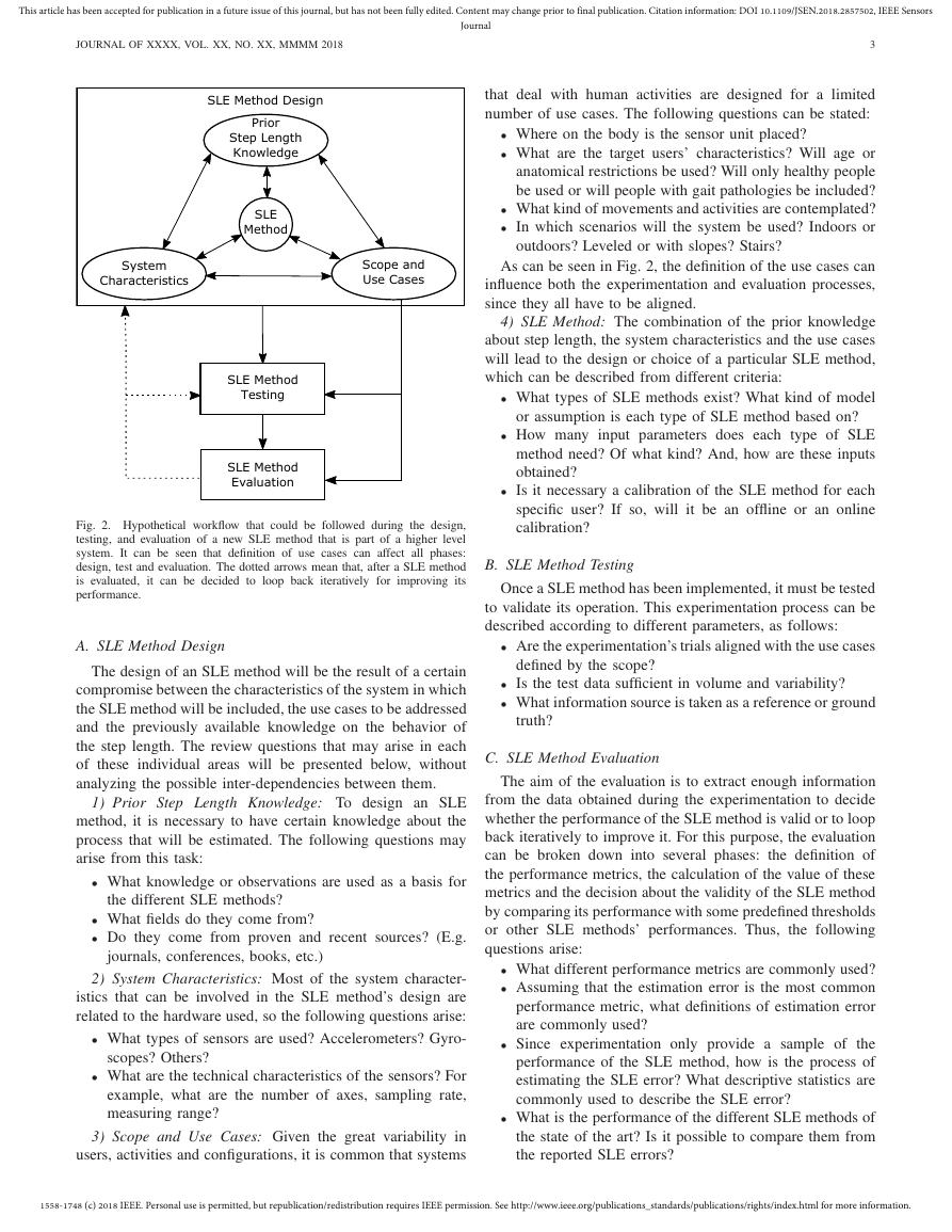
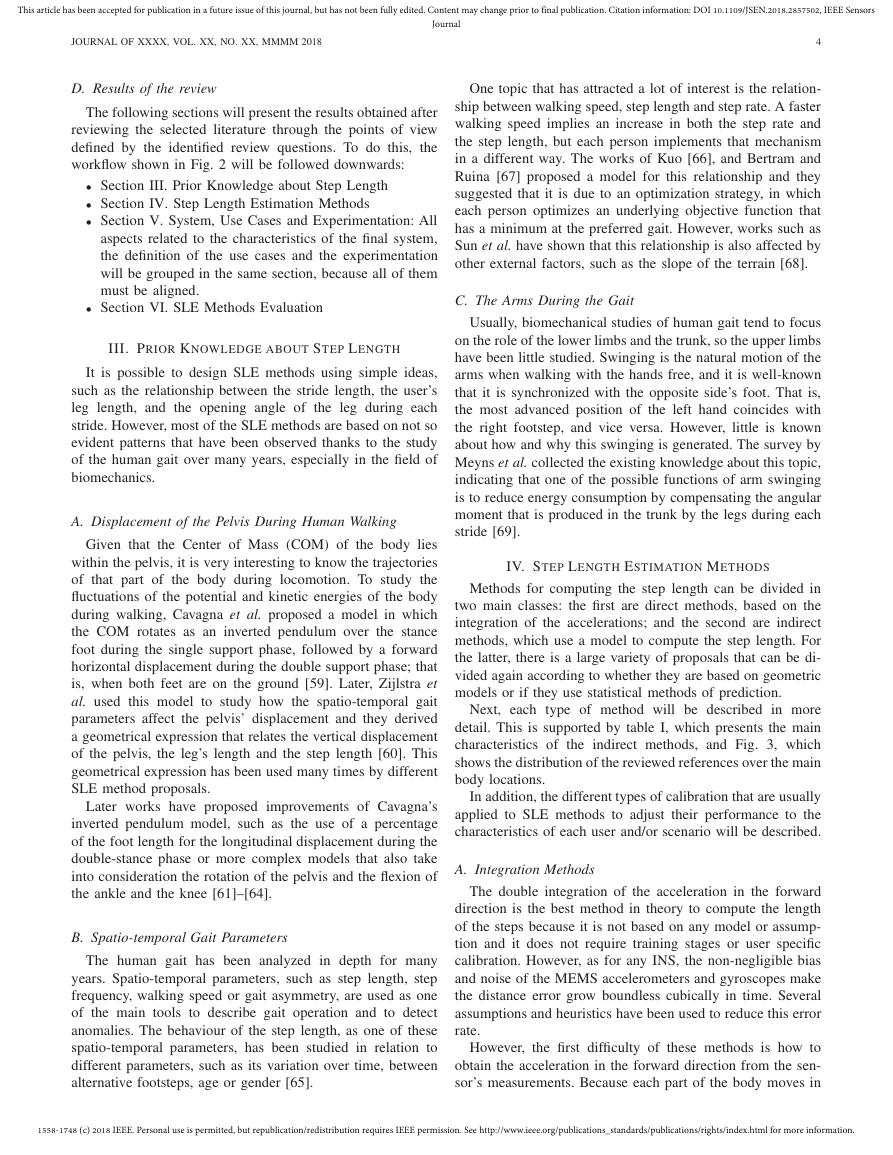
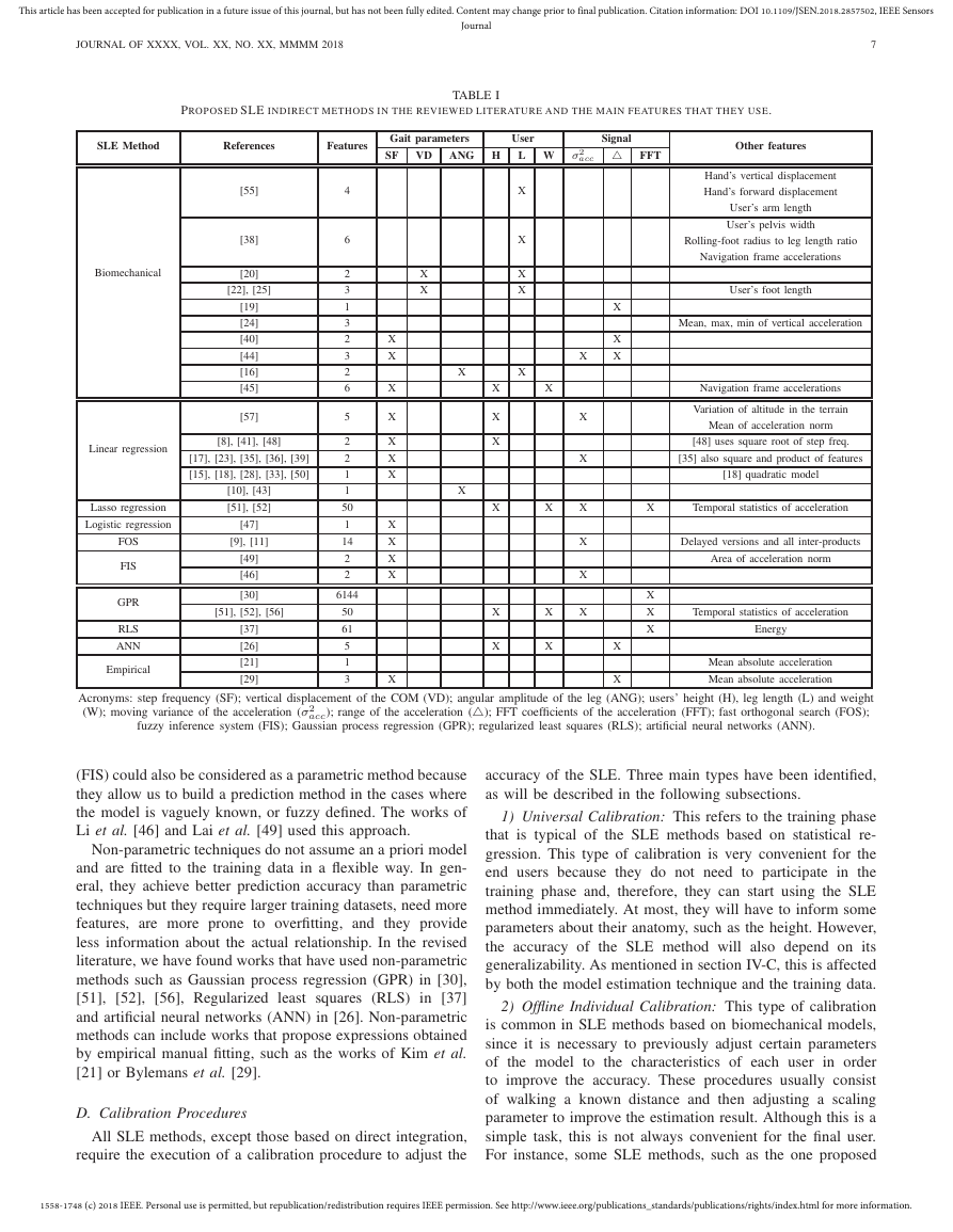
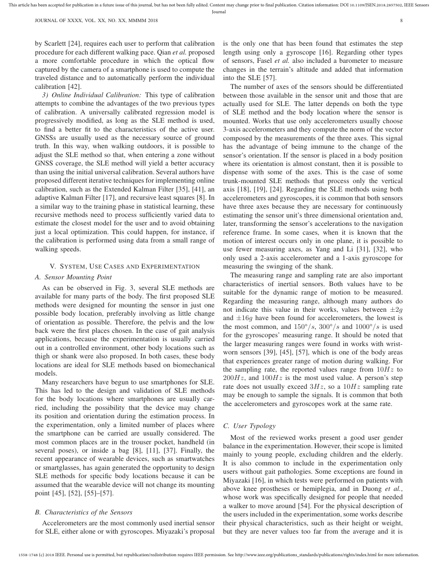
detail. This is supported by table I, which presents the main
characteristics of the indirect methods, and Fig. 3, which
shows the distribution of the reviewed references over the main
body locations.
In addition, the different types of calibration that are usually
applied to SLE methods to adjust their performance to the
characteristics of each user and/or scenario will be described.
A. Integration Methods
The double integration of the acceleration in the forward
direction is the best method in theory to compute the length
of the steps because it is not based on any model or assump-
tion and it does not require training stages or user specific
calibration. However, as for any INS, the non-negligible bias
and noise of the MEMS accelerometers and gyroscopes make
the distance error grow boundless cubically in time. Several
assumptions and heuristics have been used to reduce this error
rate.
However, the first difficulty of these methods is how to
obtain the acceleration in the forward direction from the sen-
sor’s measurements. Because each part of the body moves in
1558-1748 (c) 2018 IEEE. Personal use is permitted, but republication/redistribution requires IEEE permission. See http://www.ieee.org/publications_standards/publications/rights/index.html for more information.
�
This article has been accepted for publication in a future issue of this journal, but has not been fully edited. Content may change prior to final publication. Citation information: DOI 10.1109/JSEN.2018.2857502, IEEE Sensors
Journal
JOURNAL OF XXXX, VOL. XX, NO. XX, MMMM 2018
5
Any place where step frequency can be sensed:
[8], [15], [18], [28], [33], [41], [47], [48], [50]
Head: [9], [11], [44], [56]
Handheld/Wrist-worn coupled to COM:
[8], [9], [11], [33], [37],
[39]–[41], [47], [48], [57]
COM: [7], [17]–[20], [22]–[25],
[28], [30], [36]–[38], [44], [49], [51]
Front Pocket/Thigh:
[10], [16], [29], [37],
[40], [43], [46]–[48]
Shank: [31], [32]
Chest: [26], [40]
Back Pocket: [40], [47]
Handheld/Wrist-worn swinging:
[8], [9], [11], [35], [37], [39], [41],
[45], [48], [50],[52], [55], [57}
Ankle: [21], [51]
Fig. 3. Distribution of the different body locations of the SLE methods from the reviewed references. The SLE methods that only depend on the step
frequency can be used on any body location in which that feature is sensed. For those SLE methods, the body location on which they were tested in the
original reference is also indicated.
different directions during walking, it is not easy to constantly
maintain a sensor parallel to the direction of travel. It is,
therefore, necessary to continuously know the orientation of
the sensor, which will involve the use of several accelerometers
and gyroscopes to transform the sensors accelerations into the
navigation reference system. Of course, this process is also
not error-free.
Li and Yang proposed mounting a 2-axis accelerometer and
a 1-axis gyroscope on the lateral side of the mid-shank [31],
[32]. Both the segmentation into strides and the transformation
of the accelerations into the navigation frame are obtained by
using the angle obtained by integrating the gyroscope’s angular
rate. They use the vertical position of the shank to divide the
stride segments and they assume that the initial velocity in
that moment is zero. After integration, they also assume that
the net acceleration during one stride was zero to correct the
error of the accelerometers.
K¨ose et al. proposed a system that requires a 3-axis ac-
celerometer and a 2-axis gyroscope that are placed on one side
of the pelvis [7]. They are able to detect and differentiate the
steps of each foot by using wavelet decomposition. They then
compute the length of each step using a combination of direct
and reverse integrations of high-pass filtered accelerations.
The fact that only these two works have been found and
that both are focused on gait analysis, where the environment
is usually more controlled and the time of use is shorter than
in positioning applications, highlights that these integration
techniques are less suitable for positioning than ZUPT for foot-
mounted sensors.
B. Biomechanical Models
Due to the mechanical nature of the human body, it is
possible to define analytical expressions of the step length
based on geometrical relations between some dimensions,
angles, and displacements of different parts of the body. The
advantage of using biomechanical models is that it allows
a good understanding of the relationships on which the es-
timation of the step length is built. However, due to the
complexity of the human body and the great variability of
people and scenarios, these models are usually simplifications
and approximations that require calibration phases to adjust
their performance to each specific user and walking pace.
Miyazaki used a simple geometric model
in which he
estimated the stride length using the leg length and the opening
angle during the stride [16]. To measure this angle, he used a 1-
axis gyroscope mounted on the thigh. Miyazaki found that the
error in the estimation of this model depends on the walking
speed, so he introduced an adaptive correction parameter to
address this issue.
Several SLE method proposals have emerged from the
relationship between the vertical displacement of the pelvis
and step length, as described in section III-A: Using the
inverted COM pendulum model, Zijlstra and Hof derived [20]
the geometric expression (1) that relates the step length, the
length of the user’s leg (L), and the vertical displacement of
the COM during the stance phase (H), which is obtained by
1558-1748 (c) 2018 IEEE. Personal use is permitted, but republication/redistribution requires IEEE permission. See http://www.ieee.org/publications_standards/publications/rights/index.html for more information.
�
This article has been accepted for publication in a future issue of this journal, but has not been fully edited. Content may change prior to final publication. Citation information: DOI 10.1109/JSEN.2018.2857502, IEEE Sensors
Journal
JOURNAL OF XXXX, VOL. XX, NO. XX, MMMM 2018
6
double integration of the high-pass filtered vertical acceleration
of a sensor placed on the low back. However, they found that
this model tends to underestimate the step length and that a
calibration parameter is needed to adjust the performance to
each user.
SL = 2p2LH − H 2
(1)
Alvarez and Gonzalez proposed several modifications of
Zijlstra’s model, such as the use of heuristics to reduce the
integration drift error in [22] or the inclusion of the length
of the user’s foot as a predictor of the forward displacement
during the double-stance phase in [25].
There are also works that are based on the same biome-
chanical observation but which propose empirically simplified
expressions to avoid the integration: Weinberg proposed in
[19] the expression (2), which is proportional to the amplitude
of the vertical acceleration during a step. Later, Scarlett
proposed an alternative expression that also took into account
the dispersion of the vertical acceleration during the step,
looking for a better adaptation to different users [24]. Neither
expression contained a parameter related to the user’s physical
characteristics and, therefore, they need to be calibrated for
each user and each walking pace.
SL = K 4pAmax − Amin
(2)
In an attempt to simplify the calibration process at different
paces, Mikov et al. substituted the calibration parameter in
Weinberg’s expression by the time duration of the step [40].
In a more general way, Zhu et al. substituted this with a linear
regression model of the step frequency and the acceleration
variance during a step [44].
More complex biomechanical models have also been used,
such as in Hu et al., where the authors used a pelvic displace-
ment model that takes into account the knee and ankle flexion
during the stance phase, which is often known as rolling-feet.
They derived a dynamic model of the pelvis and they estimated
the walking speed using an unscented Kalman filter [38].
Although the inverted pendulum model offers simplicity and
acceptable performance, it usually requires the accelerometers
to be as close to the COM as possible. Recently, Jiang et
al. proposed a geometric model in which they estimated the
COM’s vertical displacement from a wrist-worn sensor during
arm swinging [55]. They used some assumptions about the
synchronization between the vertical movements of the trunk
and the hand, which have not been referenced or demonstrated.
However, this is a novel proposal that reflects the potential of
using knowledge about the body’s mechanical structure. Also
for a wrist-worn sensor, Bertstchi et al. proposed a walking
speed estimation method that is based on a biomechanical
explanation of the purpose of the arm swinging; that is, the
compensation of the torque generated by the legs in the trunk.
They claimed that walking speed is proportional to both the
step frequency and to this torque, which they modeled as a
non-linear function whose expression is not described because
the patent is pending [45].
C. Statistical Regression Methods
Statistical regression methods seek to estimate the relation-
ships among variables, which is useful for predicting the value
of a variable that is difficult to obtain from the values of other
variables that are easier to measure. These latter variables are
known as features or predictors. As seen in section III-B, there
is a clear relationship between step frequency and step length,
and also with other variables. Therefore, they can be used as
predictors of the step length and, thanks to the periodicity of
human gait and the mechanical nature of the human body,
some of them can be measured from different body locations,
and by using different techniques and sensors. This flexibility
is one of the main reasons to use statistical models for SLE.
The features used in the SLE methods of the reviewed articles
can be observed in table I.
The task of estimating the relationship between the variables
of interest is usually known as training. The data and the model
estimation techniques used during this task will affect the
accuracy and the generalizability of the subsequent estimation
of the step length. There are two types of model estimation
techniques: parametric and non-parametric.
Parametric techniques assume an a priori type of model.
Generally, they are simple models with a low number of
predictors, which can provide a certain insight about the real
relationship. However, if the selected a priori model is very
different from the real one, then the prediction accuracy will
be low. The simplest and most commonly used parametric
technique is the linear regression (or ordinary least squares).
It is assumed that step length is a linear combination of
the features, using as fitting criteria the minimization of the
quadratic error. Many works use this technique with the step
frequency as the only feature ([15], [28], [33], [50]), or they
also add the variance of the acceleration over a step ([17],
[23], [36], [39]), or a greater number of features, such as
Fasel et al. [57]. Although the step frequency is the most
common predictor, there are works that are based on other
features. For example, Diaz et al. proposed to use an inertial
sensor mounted on the thigh and they built a linear regression
model using the amplitude of the variation of the leg’s pitch
as the only predictor [10], [43]. The linearity criterion refers
to the parameters that fit the model and it does not refer to the
predictors. Consequently, it is also common to find proposals
that use transformed versions of the features and/or products
of several features.
in which the linear model
In general, using more predictors helps to get better pre-
dictions but there is a higher risk of overfitting the model
to the training data. To reduce this, Zihajehzadeh et al. used
the Lasso regression,
is fitted
by minimizing a penalized version of the least squares loss
function [51], [52]. This makes it possible to include a large
number of features into the training, but the model is fitted
by using only a selection of them. Some proposals have
used non-linear models. For example, the logistic regression
used in [47], or system identification techniques, such as Fast
Orthogonal Search (FOS) used in [9], [11], in which the
feature selection is made from a set that also includes values
of features of previous taken steps. Fuzzy inference systems
1558-1748 (c) 2018 IEEE. Personal use is permitted, but republication/redistribution requires IEEE permission. See http://www.ieee.org/publications_standards/publications/rights/index.html for more information.
�
This article has been accepted for publication in a future issue of this journal, but has not been fully edited. Content may change prior to final publication. Citation information: DOI 10.1109/JSEN.2018.2857502, IEEE Sensors
JOURNAL OF XXXX, VOL. XX, NO. XX, MMMM 2018
Journal
TABLE I
PROPOSED SLE INDIRECT METHODS IN THE REVIEWED LITERATURE AND THE MAIN FEATURES THAT THEY USE.
7
SLE Method
References
Features
Gait parameters
User
Signal
SF
VD
ANG H
L W σ2
acc △ FFT
Biomechanical
[55]
[38]
[20]
[22], [25]
[19]
[24]
[40]
[44]
[16]
[45]
[57]
Linear regression
[8], [41], [48]
[17], [23], [35], [36], [39]
[15], [18], [28], [33], [50]
Lasso regression
Logistic regression
FOS
FIS
GPR
RLS
ANN
Empirical
[10], [43]
[51], [52]
[47]
[9], [11]
[49]
[46]
[30]
[51], [52], [56]
[37]
[26]
[21]
[29]
4
6
2
3
1
3
2
3
2
6
5
2
2
1
1
50
1
14
2
2
6144
50
61
5
1
3
X
X
X
X
X
X
X
X
X
X
X
X
X
X
X
X
X
X
X
X
X
X
X
X
X
X
X
X
X
X
X
X
X
X
X
X
X
X
X
X
X
X
X
Other features
Hand’s vertical displacement
Hand’s forward displacement
User’s arm length
User’s pelvis width
Rolling-foot radius to leg length ratio
Navigation frame accelerations
User’s foot length
Mean, max, min of vertical acceleration
Navigation frame accelerations
Variation of altitude in the terrain
Mean of acceleration norm
[48] uses square root of step freq.
[35] also square and product of features
[18] quadratic model
X
Temporal statistics of acceleration
Delayed versions and all inter-products
Area of acceleration norm
X
X
X
Temporal statistics of acceleration
Energy
Mean absolute acceleration
Mean absolute acceleration
Acronyms: step frequency (SF); vertical displacement of the COM (VD); angular amplitude of the leg (ANG); users’ height (H), leg length (L) and weight
(W); moving variance of the acceleration (σ2
acc); range of the acceleration (△); FFT coefficients of the acceleration (FFT); fast orthogonal search (FOS);
fuzzy inference system (FIS); Gaussian process regression (GPR); regularized least squares (RLS); artificial neural networks (ANN).
(FIS) could also be considered as a parametric method because
they allow us to build a prediction method in the cases where
the model is vaguely known, or fuzzy defined. The works of
Li et al. [46] and Lai et al. [49] used this approach.
Non-parametric techniques do not assume an a priori model
and are fitted to the training data in a flexible way. In gen-
eral, they achieve better prediction accuracy than parametric
techniques but they require larger training datasets, need more
features, are more prone to overfitting, and they provide
less information about the actual relationship. In the revised
literature, we have found works that have used non-parametric
methods such as Gaussian process regression (GPR) in [30],
[51], [52], [56], Regularized least squares (RLS) in [37]
and artificial neural networks (ANN) in [26]. Non-parametric
methods can include works that propose expressions obtained
by empirical manual fitting, such as the works of Kim et al.
[21] or Bylemans et al. [29].
D. Calibration Procedures
All SLE methods, except those based on direct integration,
require the execution of a calibration procedure to adjust the
accuracy of the SLE. Three main types have been identified,
as will be described in the following subsections.
1) Universal Calibration: This refers to the training phase
that is typical of the SLE methods based on statistical re-
gression. This type of calibration is very convenient for the
end users because they do not need to participate in the
training phase and, therefore, they can start using the SLE
method immediately. At most, they will have to inform some
parameters about their anatomy, such as the height. However,
the accuracy of the SLE method will also depend on its
generalizability. As mentioned in section IV-C, this is affected
by both the model estimation technique and the training data.
2) Offline Individual Calibration: This type of calibration
is common in SLE methods based on biomechanical models,
since it is necessary to previously adjust certain parameters
of the model to the characteristics of each user in order
to improve the accuracy. These procedures usually consist
of walking a known distance and then adjusting a scaling
parameter to improve the estimation result. Although this is a
simple task, this is not always convenient for the final user.
For instance, some SLE methods, such as the one proposed
1558-1748 (c) 2018 IEEE. Personal use is permitted, but republication/redistribution requires IEEE permission. See http://www.ieee.org/publications_standards/publications/rights/index.html for more information.
�
This article has been accepted for publication in a future issue of this journal, but has not been fully edited. Content may change prior to final publication. Citation information: DOI 10.1109/JSEN.2018.2857502, IEEE Sensors
Journal
JOURNAL OF XXXX, VOL. XX, NO. XX, MMMM 2018
8
by Scarlett [24], requires each user to perform that calibration
procedure for each different walking pace. Qian et al. proposed
a more comfortable procedure in which the optical flow
captured by the camera of a smartphone is used to compute the
traveled distance and to automatically perform the individual
calibration [42].
3) Online Individual Calibration: This type of calibration
attempts to combine the advantages of the two previous types
of calibration. A universally calibrated regression model is
progressively modified, as long as the SLE method is used,
to find a better fit to the characteristics of the active user.
GNSSs are usually used as the necessary source of ground
truth. In this way, when walking outdoors, it is possible to
adjust the SLE method so that, when entering a zone without
GNSS coverage, the SLE method will yield a better accuracy
than using the initial universal calibration. Several authors have
proposed different iterative techniques for implementing online
calibration, such as the Extended Kalman Filter [35], [41], an
adaptive Kalman Filter [17], and recursive least squares [8]. In
a similar way to the training phase in statistical learning, these
recursive methods need to process sufficiently varied data to
estimate the closest model for the user and to avoid obtaining
just a local optimization. This could happen, for instance, if
the calibration is performed using data from a small range of
walking speeds.
V. SYSTEM, USE CASES AND EXPERIMENTATION
A. Sensor Mounting Point
As can be observed in Fig. 3, several SLE methods are
available for many parts of the body. The first proposed SLE
methods were designed for mounting the sensor in just one
possible body location, preferably involving as little change
of orientation as possible. Therefore, the pelvis and the low
back were the first places chosen. In the case of gait analysis
applications, because the experimentation is usually carried
out in a controlled environment, other body locations such as
thigh or shank were also proposed. In both cases, these body
locations are ideal for SLE methods based on biomechanical
models.
Many researchers have begun to use smartphones for SLE.
This has led to the design and validation of SLE methods
for the body locations where smartphones are usually car-
ried, including the possibility that the device may change
its position and orientation during the estimation process. In
the experimentation, only a limited number of places where
the smartphone can be carried are usually considered. The
most common places are in the trouser pocket, handheld (in
several poses), or inside a bag [8], [11], [37]. Finally, the
recent appearance of wearable devices, such as smartwatches
or smartglasses, has again generated the opportunity to design
SLE methods for specific body locations because it can be
assumed that the wearable device will not change its mounting
point [45], [52], [55]–[57].
B. Characteristics of the Sensors
Accelerometers are the most commonly used inertial sensor
for SLE, either alone or with gyroscopes. Miyazaki’s proposal
is the only one that has been found that estimates the step
length using only a gyroscope [16]. Regarding other types
of sensors, Fasel et al. also included a barometer to measure
changes in the terrain’s altitude and added that information
into the SLE [57].
The number of axes of the sensors should be differentiated
between those available in the sensor unit and those that are
actually used for SLE. The latter depends on both the type
of SLE method and the body location where the sensor is
mounted. Works that use only accelerometers usually choose
3-axis accelerometers and they compute the norm of the vector
composed by the measurements of the three axes. This signal
has the advantage of being immune to the change of the
sensor’s orientation. If the sensor is placed in a body position
where its orientation is almost constant, then it is possible to
dispense with some of the axes. This is the case of some
trunk-mounted SLE methods that process only the vertical
axis [18], [19], [24]. Regarding the SLE methods using both
accelerometers and gyroscopes, it is common that both sensors
have three axes because they are necessary for continuously
estimating the sensor unit’s three dimensional orientation and,
later, transforming the sensor’s accelerations to the navigation
reference frame. In some cases, when it is known that the
motion of interest occurs only in one plane, it is possible to
use fewer measuring axes, as Yang and Li [31], [32], who
only used a 2-axis accelerometer and a 1-axis gyroscope for
measuring the swinging of the shank.
The measuring range and sampling rate are also important
characteristics of inertial sensors. Both values have to be
suitable for the dynamic range of motion to be measured.
Regarding the measuring range, although many authors do
not indicate this value in their works, values between ±2g
and ±16g have been found for accelerometers, the lowest is
the most common, and 150°/s, 300°/s and 1000°/s is used
for the gyroscopes’ measuring range. It should be noted that
the larger measuring ranges were found in works with wrist-
worn sensors [39], [45], [57], which is one of the body areas
that experiences greater range of motion during walking. For
the sampling rate, the reported values range from 10Hz to
200Hz, and 100Hz is the most used value. A person’s step
rate does not usually exceed 3Hz, so a 10Hz sampling rate
may be enough to sample the signals. It is common that both
the accelerometers and gyroscopes work at the same rate.
C. User Typology
Most of the reviewed works present a good user gender
balance in the experimentation. However, their scope is limited
mainly to young people, excluding children and the elderly.
It is also common to include in the experimentation only
users without gait pathologies. Some exceptions are found in
Miyazaki [16], in which tests were performed on patients with
above knee prostheses or hemiplegia, and in Duong et al.,
whose work was specifically designed for people that needed
a walker to move around [54]. For the physical description of
the users included in the experimentation, some works describe
their physical characteristics, such as their height or weight,
but they are never values too far from the average and it is
1558-1748 (c) 2018 IEEE. Personal use is permitted, but republication/redistribution requires IEEE permission. See http://www.ieee.org/publications_standards/publications/rights/index.html for more information.
�


 2023年江西萍乡中考道德与法治真题及答案.doc
 2012年重庆南川中考生物真题及答案.doc
 2013年江西师范大学地理学综合及文艺理论基础考研真题.doc
 2020年四川甘孜小升初语文真题及答案I卷.doc
 2020年注册岩土工程师专业基础考试真题及答案.doc
 2023-2024学年福建省厦门市九年级上学期数学月考试题及答案.doc
 2021-2022学年辽宁省沈阳市大东区九年级上学期语文期末试题及答案.doc
 2022-2023学年北京东城区初三第一学期物理期末试卷及答案.doc
 2018上半年江西教师资格初中地理学科知识与教学能力真题及答案.doc
 2012年河北国家公务员申论考试真题及答案-省级.doc
 2020-2021学年江苏省扬州市江都区邵樊片九年级上学期数学第一次质量检测试题及答案.doc
 2022下半年黑龙江教师资格证中学综合素质真题及答案.doc