前
言
我们设计的选题是基于 FPGA 的 8 位数字频率计系统。数字频率计是一
种用十进制数字显示被测信号频率的数字测量仪,它的基本功能是测量正弦信
号、方波信号、尖脉冲信号及其它各种单位时间内周期性变化的电信号,被广
泛应用于航天、电子、测控等领域。
任 务 书
出租车按照行驶 2.0 元/km 标准计算收费。计算规则为:
(1) 基本要求
a. 启动计费器开始计费,计费器显示基价(白天 10 元,夜晚 11 元)。基价公
里为 3km,
b. 行驶超过基价公里(含)但不足 15km 时,按白天 2.0 元/km、夜晚 2.4 元/km
计算标准累加计费。
c. 行驶超过 15/km(含)时,按白天 3.0 元/km、夜晚 3.4 元/km 计算标准累加
计费。
d. 当处于低速行车档或汽车停止时,启动等候计时系统,每等候满 5min 累加
2.0 元。若等候时间已满 5min,但未超过基价公里,则提前进行累加计费。
e. 实时显示千元以内的结算金额。
f. 白天、夜晚以 5:00 和 23:00 界定。
g. 计费器停止计费时,计费金额以元为基数四舍五入取整。打印计费清单后,
计费器自动清零。
(2)提高要求
a.白天计费方式:基价 10 元,基价公里为 3km。以后路程每增加 1km,计费
器进行累加计费。15km 以下,每公里单价费用 2.0 元。15km 以上,每公里单
价费用 3.0 元。
b.夜晚计费方式:基价 11 元,基价公里为 3km。以后路程每增加 1km,计价
器进行累加计算。15km 以下,每公里单价费用为 2.4 元。实施每公里费用增
加 2 元,剩余费用(即 0.4 元)进行累加,每等于或超过 1 元时,费用增加一
元。15km 以上(包含 15km),每公里单价费用 3.4 元,实施每公里费用为 3
元,剩余费用(即 0.4 元)进行累加,每等于或超过 1 元时,费用增加 1 元。
c.等候计时计费:若汽车行驶路程不足基价公里,但等候计时已满 5min,则费
用增加 2 元。并提前进行累加计费。以后等候时间每满 5min,费用增加 2 元。
d.可稳定显示实时时间(时,分)、等候时间(分、秒)、里程单价、行驶里程、
行驶计费。
e.基准时钟(时、分)可调。
1
�
目录
一.设计任务..................................................................................................................................2
二.总体设计方案..........................................................................................................................4
三.各底层模块设计......................................................................................................................3
1.分频模块.............................................................................................................................................3
2.计程模块.............................................................................................................................................5
3.计费模块.............................................................................................................................................6
四.总体设计..................................................................................................................................8
1.引脚配置.............................................................................................................................................8
2.原理图..................................................................................................................................................8
五.设计总结..................................................................................................................................9
2
�
一.总体设计方案
.
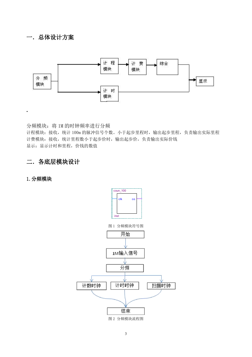
分频模块:将 1M 的时钟频率进行分频
计程模块:接收,统计 100m 的脉冲信号个数。小于起步里程时,输出起步里程,负责输出实际里程
计费模块:接收,统计里程数小于起步价时,输出起步价,负责输出实际价钱
显示:显示计时和里程,价钱的数值
二.各底层模块设计
1.分频模块
coun_100
clk
co
inst
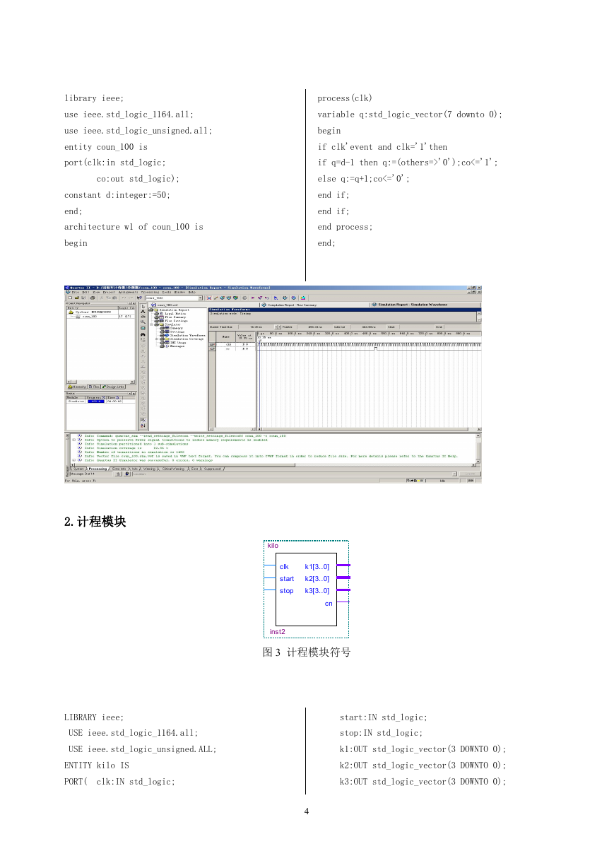
图 1 分频模块符号图
图 2 分频模块流程图
3
�
library ieee;
process(clk)
use ieee.std_logic_1164.all;
variable q:std_logic_vector(7 downto 0);
use ieee.std_logic_unsigned.all;
begin
entity coun_100 is
port(clk:in std_logic;
co:out std_logic);
constant d:integer:=50;
end;
architecture w1 of coun_100 is
begin
if clk'event and clk='1'then
if q=d-1 then q:=(others=>'0');co<='1';
else q:=q+1;co<='0';
end if;
end if;
end process;
end;
2.计程模块
kilo
clk
start
stop
k1[3..0]
k2[3..0]
k3[3..0]
cn
inst2
图 3 计程模块符号
LIBRARY ieee;
USE ieee.std_logic_1164.all;
start:IN std_logic;
stop:IN std_logic;
USE ieee.std_logic_unsigned.ALL;
k1:OUT std_logic_vector(3 DOWNTO 0);
ENTITY kilo IS
PORT( clk:IN std_logic;
k2:OUT std_logic_vector(3 DOWNTO 0);
k3:OUT std_logic_vector(3 DOWNTO 0);
4
�
cn:out std_logic);
END kilo;
ARCHITECTURE behav OF kilo IS
BEGIN
PROCESS(clk,start,stop)
VARIABLE k_v:std_logic_vector(11 DOWNTO 0);
END IF;
IF k_v(7 downto 4)="1010" THEN
k_v:=k_v+"01100000";
END IF;
END IF;
END IF;
BEGIN
IF k_v(11 downto 0)>="000001000000" THEN
IF stop='1' THEN k_v:=(OTHERS=>'0');
cn<='1';else cn<='0';
ELSIF clk'EVENT AND clk='1'THEN
END IF;
IF start='1' THEN
IF k_v(3 downto 0)="1001" THEN
k_v:=k_v+"0111";
ELSE
k1<=k_v(3 downto 0);
k2<=k_v(7 downto 4);
k3<=k_v(11 downto 8);
END PROCESS;
k_v(3 downto 0):=k_v(3 downto 0)+1;
END behav;
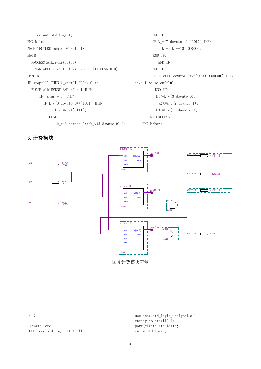
3.计费模块
clk
cn
rest
INPUT
VCC
INPUT
VCC
INPUT
VCC
counter110
clk
en
rest
inst
cq[3..0]
cout
cq1[3..0]
OUTPUT
cq1[3..0]
OUTPUT
cq2[3..0]
cq2[3..0]
OUTPUT
cq3[3..0]
cq[3..0]
cout
AND2
inst4
cq[3..0]
cout
cq3[3..0]
AND2
inst5
OUTPUT
cout
counter10
clk
en
rest
inst2
counter_10
clk
en
cn
rest
inst1
图 4 计费模块符号
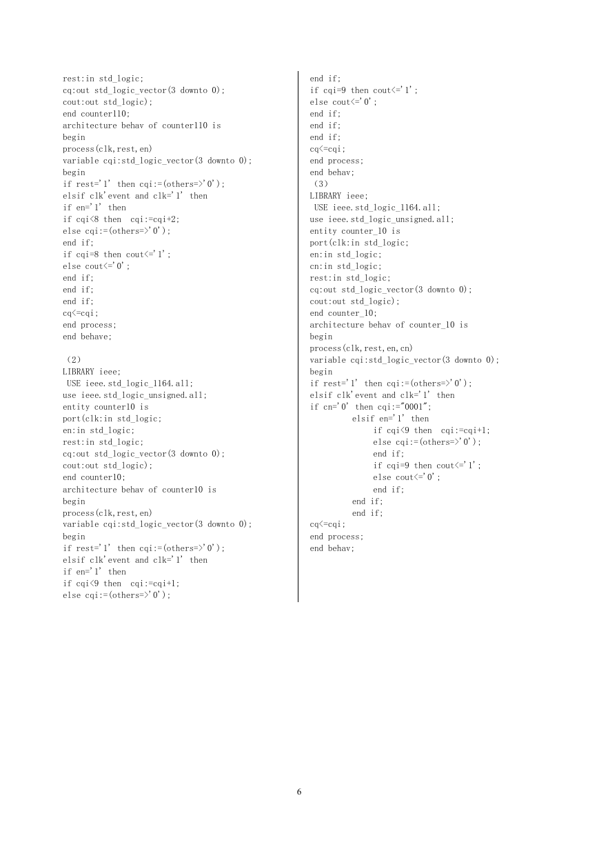
(1)
LIBRARY ieee;
USE ieee.std_logic_1164.all;
use ieee.std_logic_unsigned.all;
entity counter110 is
port(clk:in std_logic;
en:in std_logic;
5
�
rest:in std_logic;
cq:out std_logic_vector(3 downto 0);
cout:out std_logic);
end counter110;
architecture behav of counter110 is
begin
process(clk,rest,en)
variable cqi:std_logic_vector(3 downto 0);
begin
if rest='1' then cqi:=(others=>'0');
elsif clk'event and clk='1' then
if en='1' then
if cqi<8 then cqi:=cqi+2;
else cqi:=(others=>'0');
end if;
if cqi=8 then cout<='1';
else cout<='0';
end if;
end if;
end if;
cq<=cqi;
end process;
end behave;
(2)
LIBRARY ieee;
USE ieee.std_logic_1164.all;
use ieee.std_logic_unsigned.all;
entity counter10 is
port(clk:in std_logic;
en:in std_logic;
rest:in std_logic;
cq:out std_logic_vector(3 downto 0);
cout:out std_logic);
end counter10;
architecture behav of counter10 is
begin
process(clk,rest,en)
variable cqi:std_logic_vector(3 downto 0);
begin
if rest='1' then cqi:=(others=>'0');
elsif clk'event and clk='1' then
if en='1' then
if cqi<9 then cqi:=cqi+1;
else cqi:=(others=>'0');
end if;
if cqi=9 then cout<='1';
else cout<='0';
end if;
end if;
end if;
cq<=cqi;
end process;
end behav;
(3)
LIBRARY ieee;
USE ieee.std_logic_1164.all;
use ieee.std_logic_unsigned.all;
entity counter_10 is
port(clk:in std_logic;
en:in std_logic;
cn:in std_logic;
rest:in std_logic;
cq:out std_logic_vector(3 downto 0);
cout:out std_logic);
end counter_10;
architecture behav of counter_10 is
begin
process(clk,rest,en,cn)
variable cqi:std_logic_vector(3 downto 0);
begin
if rest='1' then cqi:=(others=>'0');
elsif clk'event and clk='1' then
if cn='0' then cqi:="0001";
elsif en='1' then
if cqi<9 then cqi:=cqi+1;
else cqi:=(others=>'0');
end if;
if cqi=9 then cout<='1';
else cout<='0';
end if;
end if;
end if;
cq<=cqi;
end process;
end behav;
6
�
三.总体设计
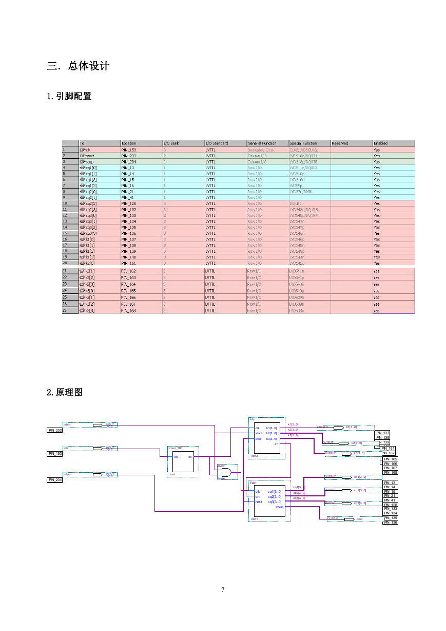
1.引脚配置
2.原理图
start
PIN_233
clk
PIN_153
stop
PIN_234
INPUT
VCC
INPUT
VCC
INPUT
VCC
kilo
clk
start
stop
k1[3..0]
k2[3..0]
k3[3..0]
cn
k1[3..0]
k2[3..0]
k3[3..0]
inst2
fee
cq1[3..0]
cq2[3..0]
cq3[3..0]
clk
cn
rest
cq1[3..0]
cq2[3..0]
cq3[3..0]
cout
OUTPUT
k1[3..0]
OUTPUT
k2[3..0]
OUTPUT
k3[3..0]
OUTPUT
cq1[3..0]
OUTPUT
cq2[3..0]
OUTPUT
cq3[3..0]
inst1
OUTPUT
cout
coun_100
clk
co
inst
AND2
inst4
7
PIN_137
PIN_138
PIN_139
PIN_140
PIN_161
PIN_162
PIN_163
PIN_164
PIN_165
PIN_166
PIN_167
PIN_168
PIN_13
PIN_14
PIN_15
PIN_21
PIN_16
PIN_41
PIN_128
PIN_133
PIN_132
PIN_134
PIN_135
PIN_136
�
四.设计总结
这个学期的期末,我们进行了两周的实训课程—FPGA 设计基础。了解到
了时序电路和各个触发器的功能和作用,通过 FPGA 技术,我们可以做出出租
车计价器组件的设计,通过语句来编写需要的语句,还有仿真。考虑模块和原
理图,连接相应的引脚,就基本完成了程序设计,这些都要依靠小组成员相互
的信任分工和探讨,有时候还要向老师寻求帮助,上网和在图书馆查找提供的
参考资料。这次试训不仅仅掌握了编程的学习,还明白了小组学习的意义。
五.参考文献
《FPGA 设计基础》
8
�


 2023年江西萍乡中考道德与法治真题及答案.doc
 2012年重庆南川中考生物真题及答案.doc
 2013年江西师范大学地理学综合及文艺理论基础考研真题.doc
 2020年四川甘孜小升初语文真题及答案I卷.doc
 2020年注册岩土工程师专业基础考试真题及答案.doc
 2023-2024学年福建省厦门市九年级上学期数学月考试题及答案.doc
 2021-2022学年辽宁省沈阳市大东区九年级上学期语文期末试题及答案.doc
 2022-2023学年北京东城区初三第一学期物理期末试卷及答案.doc
 2018上半年江西教师资格初中地理学科知识与教学能力真题及答案.doc
 2012年河北国家公务员申论考试真题及答案-省级.doc
 2020-2021学年江苏省扬州市江都区邵樊片九年级上学期数学第一次质量检测试题及答案.doc
 2022下半年黑龙江教师资格证中学综合素质真题及答案.doc