OV7670 Software Application Note
Table of Contents
OV7670 Software Application Note.................................................................................................... 1
1. Select Output format....................................................................................................................3
1.1 Backend with full ISP........................................................................................................... 3
1.2 Backend with YCbCr ISP..................................................................................................... 4
1.3 Backend without ISP.............................................................................................................4
1.4 Equations to Convert from One Format to Another............................................................. 4
2. Select Output Resolution?........................................................................................................... 5
2.1 Backend with ISP..................................................................................................................5
2.2 Backend without ISP.............................................................................................................5
3. Adjust frame rate......................................................................................................................... 5
3.1 Frame Rate Adjustment for 24Mhz input clock....................................................................5
30 fps, PCLK = 24Mhz.......................................................................................................... 5
15 fps, PCLK = 12Mhz.......................................................................................................... 5
25fps, PCLK = 24Mhz........................................................................................................... 5
14.3fps, PCLK = 12Mhz........................................................................................................ 6
3.2 Frame Rate Adjustment for 26 Mhz input clock...................................................................6
30 fps, PCLK = 26Mhz.......................................................................................................... 6
15 fps, PCLK = 13Mhz.......................................................................................................... 6
25fps, PCLK = 26Mhz........................................................................................................... 6
14.3fps, PCLK = 13Mhz........................................................................................................ 7
3.3 Frame rate adjustment for 13 Mhz input clock..................................................................... 7
30 fps, PCLK = 26Mhz.......................................................................................................... 7
15 fps, PCLK = 13Mhz.......................................................................................................... 7
25fps, PCLK = 26Mhz........................................................................................................... 7
14.3fps, PCLK = 13Mhz........................................................................................................ 7
4. Night Mode..................................................................................................................................8
4.1 Night Mode with Fixed Frame Rate..................................................................................... 8
For 24Mhz/26Mhz Clock Input..............................................................................................8
For 13Mhz Clock Input.......................................................................................................... 8
4.2 Night Mode with Auto Frame Rate.......................................................................................8
For 24Mhz/26Mhz Clock Input..............................................................................................8
For 13Mhz Clock Input.......................................................................................................... 9
5. Remove Light Band...................................................................................................................10
5.1 Light Band...........................................................................................................................10
5.2 Remove Light band.............................................................................................................10
5.3 Select Banding Filter by Region Information..................................................................... 10
Banding Filter Setting for 24Mhz Input Clock.................................................................... 11
Banding Filter Setting for 13Mhz/26Mhz Input Clock........................................................ 11
5.4 Select Banding Filter by Automatic Light Frequency Detection........................................12
Banding Filter Setting for 24Mhz Input Clock.................................................................... 12
Banding Filter Setting for 13Mhz/26Mhz Input Clock........................................................ 13
5.5 When Light Band can not be Removed.............................................................................. 14
6. White Balance............................................................................................................................14
6.1 Simple White Balance.........................................................................................................14
6.2 Advanced White Balance....................................................................................................14
�
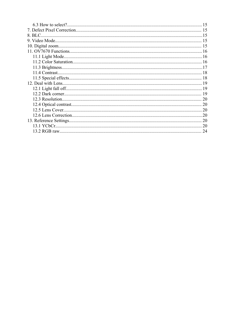
6.3 How to select?.....................................................................................................................15
7. Defect Pixel Correction............................................................................................................. 15
8. BLC............................................................................................................................................15
9. Video Mode............................................................................................................................... 15
10. Digital zoom............................................................................................................................ 15
11. OV7670 Functions...................................................................................................................16
11.1 Light Mode........................................................................................................................16
11.2 Color Saturation................................................................................................................ 16
11.3 Brightness..........................................................................................................................17
11.4 Contrast............................................................................................................................. 18
11.5 Special effects................................................................................................................... 18
12. Deal with Lens.........................................................................................................................19
12.1 Light fall off...................................................................................................................... 19
12.2 Dark corner....................................................................................................................... 19
12.3 Resolution......................................................................................................................... 20
12.4 Optical contrast................................................................................................................. 20
12.5 Lens Cover........................................................................................................................ 20
12.6 Lens Correction.................................................................................................................20
13. Reference Settings................................................................................................................... 20
13.1 YCbCr............................................................................................................................... 20
13.2 RGB raw........................................................................................................................... 24
�
1. Select Output format
OV7670 support 4 output formats: YCbCr, RGB565/RGB555, Bayer raw RGB and Processed raw
RGB. How to choose the right output format for camera phone design or other applications? Let's
look at the backend chip first.
The general diagram of backend chip is as below:
Camera Interface
YCbCr
RGB
Bayer raw RGB
Processed raw RGB
X
LCD Driver
RGB
Memory Interface
JPEG
The data format at LCD driver are always RGB. For example, RGB444, RGB565, RGB555,
RGB888 etc. The data format and memory interface are always JPEG. The JPEG data is
compressed from YCbCr data. So Both RGB and YCbCr data are needed inside the backend chip.
The “X” block is different for different backend chips.
1.1 Backend with full ISP
This kind of backend has full ISP. It takes raw RGB input, doing interpolation to generate
RGB24 and doing translation to generate YCbCr. This kind of backend could take either Bayer raw
RGB or processed raw RGB.
The advantage of processed raw RGB over Bayer raw RGB is the output data are processed.
Sensor functions such as defect pixel correction, lens correction, gamma, color matrix, de-noise,
sharpness, BLC etc. could be applied. Since the life time of backend chip is longer than image
sensor, sometimes backend chips could not fix defects of new sensors if taken Bayer raw RGB. But
the defects of new sensors could be fixed in processed raw RGB output.
If backend take Bayer raw RGB format from sensor, all the image process operations such as
defect pixel correction, lens correction, gamma, color matrix, de-noise, sharpness, BCL etc should
be done by backend. If backend take processed raw RGB format from sensor, the image process
operations such as defect pixel correction, lens correction, gamma, color matrix, de-noise,
sharpness, BCL etc could be done either inside sensor or by backend chips. In other words, user
could select the image process operation be done by which side.
�
1.2 Backend with YCbCr ISP
This kind of backend has ISP, but could take only YCbCr format. The ISP could convert YCbCr
to RGB format for LCD display and compress YCbCr to JPEG for storage.
1.3 Backend without ISP
This kind of backend doesn't have ISP built-in. It can not convert from one format to another by
hardware. Actually the format conversion is done by software. There are 3 possible solution for this
kind of backend chips.
a. Sensor output YCbCr. Backend convert YCbCr to RGB for display by software.
b. Sensor output RGB565. Backend convert RGB565 to YCbCR for JPEG compression.
c. Sensor output RGB565 for preview, output YCbCr for capture (JPEG compression).
Solution a. provide the best picture quality. Since the input data is 24-bit RGB equivalent. It
could converted to RGB888 for LCD display. Solution b. provide the worst picture quality. Since
the input data is only 16-bit RGB565, even it is converted to YCbCr, the color depth is still 16-bit.
The solution c. provide similar picture quality as solution a. But since preview is RGB565, capture
is YCbCr, preview picture may looks a little different than capture picture.
1.4 Equations to Convert from One Format to Another
YCbCr to RGB24
Y = 0.299R + 0.587G + 0.114B
Cb = 0.568(B-Y) + 128 = –0.172R – 0.339G + 0.511B + 128
Cr = 0.713(R-Y) + 128 = 0.511R – 0.428G – 0.083B + 128
Y = ((77 * R + 150 * G + 29 * B) >> 8);
Cb = ((-43 * R - 85 * G + 128 * B) >> 8) + 128;
Cr = ((128 * R - 107 * G - 21 * B) >> 8) + 128;
RGB24 to YCbCr
R = Y + 1.371(Cr – 128)
G = Y – 0.698(Cr – 128) – 0.336(Cb – 128)
B = Y + 1.732(Cb – 128)
R = Y + (351*(Cr – 128)) >> 8
G = Y – (179*(Cr – 128) + 86*(Cb – 128))>>8
B = Y + (443*(Cb – 128)) >> 8
�
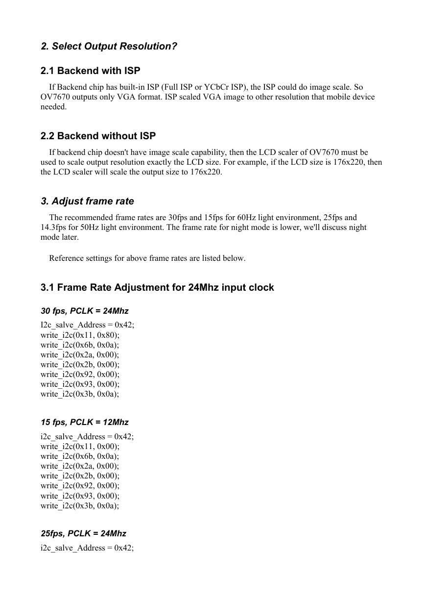
2. Select Output Resolution?
2.1 Backend with ISP
If Backend chip has built-in ISP (Full ISP or YCbCr ISP), the ISP could do image scale. So
OV7670 outputs only VGA format. ISP scaled VGA image to other resolution that mobile device
needed.
2.2 Backend without ISP
If backend chip doesn't have image scale capability, then the LCD scaler of OV7670 must be
used to scale output resolution exactly the LCD size. For example, if the LCD size is 176x220, then
the LCD scaler will scale the output size to 176x220.
3. Adjust frame rate
The recommended frame rates are 30fps and 15fps for 60Hz light environment, 25fps and
14.3fps for 50Hz light environment. The frame rate for night mode is lower, we'll discuss night
mode later.
Reference settings for above frame rates are listed below.
3.1 Frame Rate Adjustment for 24Mhz input clock
30 fps, PCLK = 24Mhz
I2c_salve_Address = 0x42;
write_i2c(0x11, 0x80);
write_i2c(0x6b, 0x0a);
write_i2c(0x2a, 0x00);
write_i2c(0x2b, 0x00);
write_i2c(0x92, 0x00);
write_i2c(0x93, 0x00);
write_i2c(0x3b, 0x0a);
15 fps, PCLK = 12Mhz
i2c_salve_Address = 0x42;
write_i2c(0x11, 0x00);
write_i2c(0x6b, 0x0a);
write_i2c(0x2a, 0x00);
write_i2c(0x2b, 0x00);
write_i2c(0x92, 0x00);
write_i2c(0x93, 0x00);
write_i2c(0x3b, 0x0a);
25fps, PCLK = 24Mhz
i2c_salve_Address = 0x42;
�
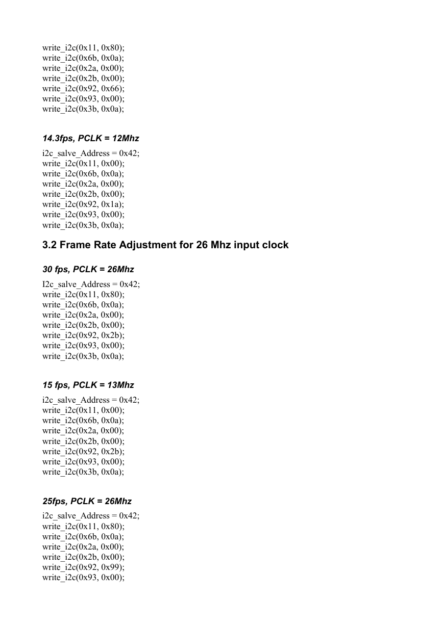
write_i2c(0x11, 0x80);
write_i2c(0x6b, 0x0a);
write_i2c(0x2a, 0x00);
write_i2c(0x2b, 0x00);
write_i2c(0x92, 0x66);
write_i2c(0x93, 0x00);
write_i2c(0x3b, 0x0a);
14.3fps, PCLK = 12Mhz
i2c_salve_Address = 0x42;
write_i2c(0x11, 0x00);
write_i2c(0x6b, 0x0a);
write_i2c(0x2a, 0x00);
write_i2c(0x2b, 0x00);
write_i2c(0x92, 0x1a);
write_i2c(0x93, 0x00);
write_i2c(0x3b, 0x0a);
3.2 Frame Rate Adjustment for 26 Mhz input clock
30 fps, PCLK = 26Mhz
I2c_salve_Address = 0x42;
write_i2c(0x11, 0x80);
write_i2c(0x6b, 0x0a);
write_i2c(0x2a, 0x00);
write_i2c(0x2b, 0x00);
write_i2c(0x92, 0x2b);
write_i2c(0x93, 0x00);
write_i2c(0x3b, 0x0a);
15 fps, PCLK = 13Mhz
i2c_salve_Address = 0x42;
write_i2c(0x11, 0x00);
write_i2c(0x6b, 0x0a);
write_i2c(0x2a, 0x00);
write_i2c(0x2b, 0x00);
write_i2c(0x92, 0x2b);
write_i2c(0x93, 0x00);
write_i2c(0x3b, 0x0a);
25fps, PCLK = 26Mhz
i2c_salve_Address = 0x42;
write_i2c(0x11, 0x80);
write_i2c(0x6b, 0x0a);
write_i2c(0x2a, 0x00);
write_i2c(0x2b, 0x00);
write_i2c(0x92, 0x99);
write_i2c(0x93, 0x00);
�
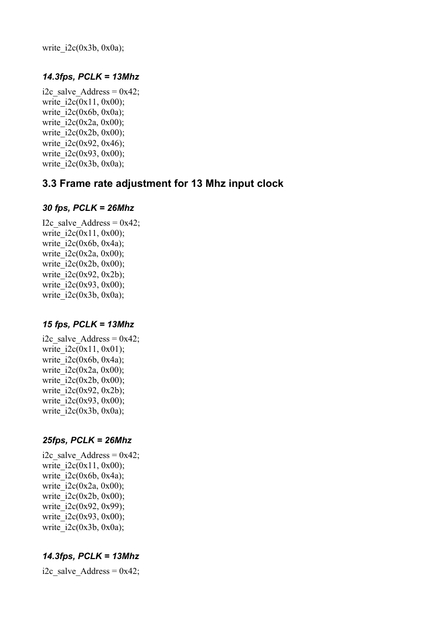
write_i2c(0x3b, 0x0a);
14.3fps, PCLK = 13Mhz
i2c_salve_Address = 0x42;
write_i2c(0x11, 0x00);
write_i2c(0x6b, 0x0a);
write_i2c(0x2a, 0x00);
write_i2c(0x2b, 0x00);
write_i2c(0x92, 0x46);
write_i2c(0x93, 0x00);
write_i2c(0x3b, 0x0a);
3.3 Frame rate adjustment for 13 Mhz input clock
30 fps, PCLK = 26Mhz
I2c_salve_Address = 0x42;
write_i2c(0x11, 0x00);
write_i2c(0x6b, 0x4a);
write_i2c(0x2a, 0x00);
write_i2c(0x2b, 0x00);
write_i2c(0x92, 0x2b);
write_i2c(0x93, 0x00);
write_i2c(0x3b, 0x0a);
15 fps, PCLK = 13Mhz
i2c_salve_Address = 0x42;
write_i2c(0x11, 0x01);
write_i2c(0x6b, 0x4a);
write_i2c(0x2a, 0x00);
write_i2c(0x2b, 0x00);
write_i2c(0x92, 0x2b);
write_i2c(0x93, 0x00);
write_i2c(0x3b, 0x0a);
25fps, PCLK = 26Mhz
i2c_salve_Address = 0x42;
write_i2c(0x11, 0x00);
write_i2c(0x6b, 0x4a);
write_i2c(0x2a, 0x00);
write_i2c(0x2b, 0x00);
write_i2c(0x92, 0x99);
write_i2c(0x93, 0x00);
write_i2c(0x3b, 0x0a);
14.3fps, PCLK = 13Mhz
i2c_salve_Address = 0x42;
�
write_i2c(0x11, 0x01);
write_i2c(0x6b, 0x4a);
write_i2c(0x2a, 0x00);
write_i2c(0x2b, 0x00);
write_i2c(0x92, 0x46);
write_i2c(0x93, 0x00);
write_i2c(0x3b, 0x0a);
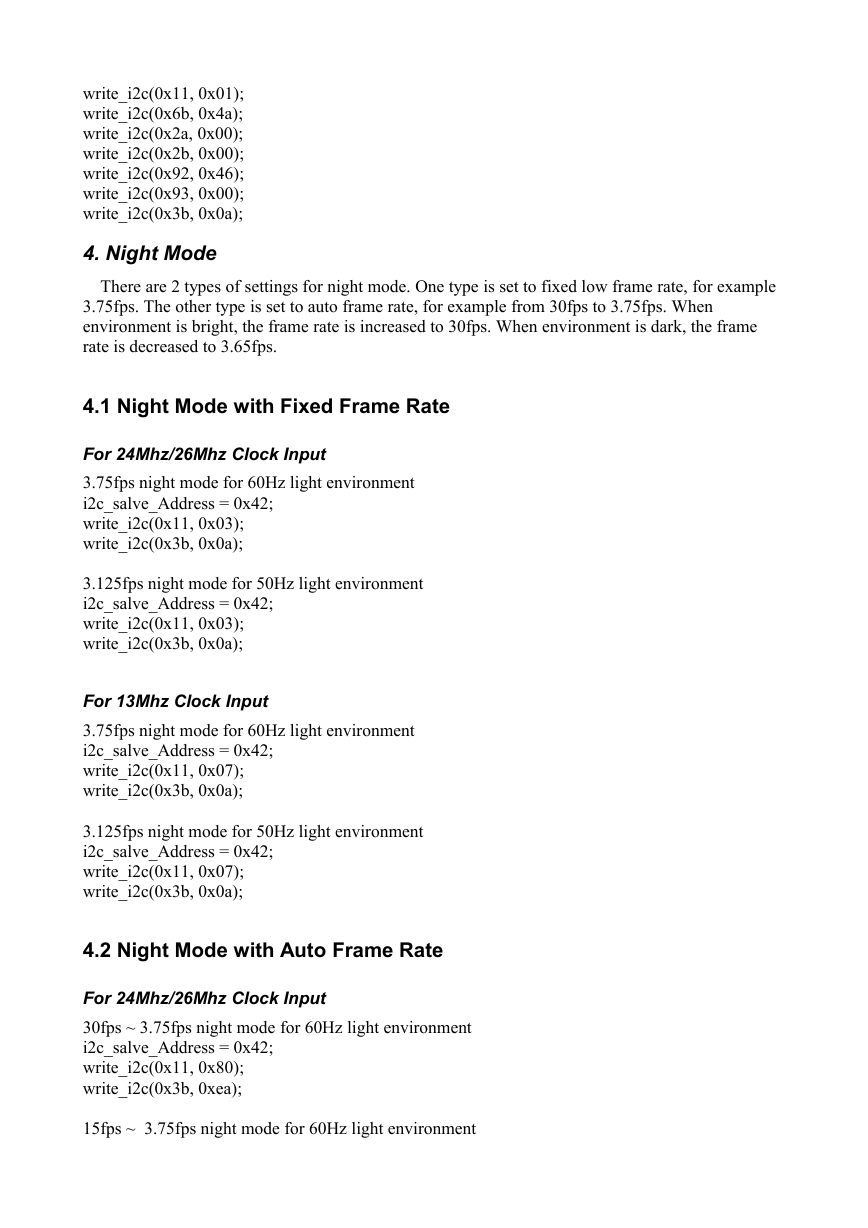
4. Night Mode
There are 2 types of settings for night mode. One type is set to fixed low frame rate, for example
3.75fps. The other type is set to auto frame rate, for example from 30fps to 3.75fps. When
environment is bright, the frame rate is increased to 30fps. When environment is dark, the frame
rate is decreased to 3.65fps.
4.1 Night Mode with Fixed Frame Rate
For 24Mhz/26Mhz Clock Input
3.75fps night mode for 60Hz light environment
i2c_salve_Address = 0x42;
write_i2c(0x11, 0x03);
write_i2c(0x3b, 0x0a);
3.125fps night mode for 50Hz light environment
i2c_salve_Address = 0x42;
write_i2c(0x11, 0x03);
write_i2c(0x3b, 0x0a);
For 13Mhz Clock Input
3.75fps night mode for 60Hz light environment
i2c_salve_Address = 0x42;
write_i2c(0x11, 0x07);
write_i2c(0x3b, 0x0a);
3.125fps night mode for 50Hz light environment
i2c_salve_Address = 0x42;
write_i2c(0x11, 0x07);
write_i2c(0x3b, 0x0a);
4.2 Night Mode with Auto Frame Rate
For 24Mhz/26Mhz Clock Input
30fps ~ 3.75fps night mode for 60Hz light environment
i2c_salve_Address = 0x42;
write_i2c(0x11, 0x80);
write_i2c(0x3b, 0xea);
15fps ~ 3.75fps night mode for 60Hz light environment
�

