logo资料库

DS-ICM-20948 v1 0 .pdf

第1页 / 共100页
第2页 / 共100页
第3页 / 共100页
第4页 / 共100页
第5页 / 共100页
第6页 / 共100页
第7页 / 共100页
第8页 / 共100页
资料共100页,剩余部分请下载后查看
Table of Tables
1 Document Information
1.1 Revision History
1.2 Purpose and Scope
1.3 Product Overview
1.4 Applications
2 Features
2.1 Gyroscope Features
2.2 Accelerometer Features
2.3 Magnetometer Features
2.4 DMP Features
2.5 Additional Features
3 Electrical Characteristics
3.1 Gyroscope Specifications
3.2 Accelerometer Specifications
3.3 Magnetometer Specifications
3.4 Electrical Specifications
11.1.1 D.C. Electrical Characteristics
21.1.1 A.C. Electrical Characteristics
31.1.1 Other Electrical Specifications
3.5 I2C Timing Characterization
3.6 SPI Timing Characterization
3.7 Absolute Maximum Ratings
4 Applications Information
4.1 Pin Out Diagram and Signal Description
4.2 Typical Operating Circuit
4.3 Bill of Materials for External Components
4.4 Exposed Die Pad Precautions
4.5 Block Diagram
4.6 Overview
4.7 Three-Axis MEMS Gyroscope with 16-bit ADCs and Signal Conditioning
4.8 Three-Axis MEMS Accelerometer with 16-bit ADCs and Signal Conditioning
4.9 Three-Axis MEMS Magnetometer with 16-bit ADCs and Signal Conditioning
4.10 Digital Motion Processor
4.11 Primary I2C and SPI Serial Communications Interfaces
41.1.1 ICM-20948 Solution Using I2C Interface
51.1.1 ICM-20948 Solution Using SPI Interface
4.12 Auxiliary I2C Serial Interface
4.13 Self-Test
4.14 Clocking
4.15 Sensor Data Registers
4.16 FIFO
4.17 FSYNC
4.18 Interrupts
4.19 Digital-Output Temperature Sensor
4.20 Bias and LDOs
4.21 Charge Pump
4.22 Power Modes
5 Programmable Interrupts
6 Digital Interface
6.1 I2C and SPI Serial Interfaces
6.2 I2C Interface
6.3 I2C Communications Protocol
6.4 I2C Terms
6.5 SPI Interface
7 Orientation of Axes
8 Package Dimensions
9 Part Number Part Markings
10 Register Map for Gyroscope and Accelerometer
11 Register Descriptions
11.1 USR Bank 0 Register Map
11.1.1 WHO_AM_I
11.1.2 USER_CTRL
11.1.3 LP_CONFIG
11.1.4 PWR_MGMT_1
11.1.5 PWR_MGMT_2
11.1.6 INT_PIN_CFG
11.1.7 INT_ENABLE
11.1.8 INT_ENABLE_1
11.1.9 INT_ENABLE_2
11.1.10 INT_ENABLE_3
11.1.11 I2C_MST_STATUS
11.1.12 INT_STATUS
11.1.13 INT_STATUS_1
11.1.14 INT_STATUS_2
11.1.15 INT_STATUS_3
11.1.16 DELAY_TIMEH
11.1.17 DELAY_TIMEL
11.1.18 ACCEL_XOUT_H
11.1.19 ACCEL_XOUT_L
11.1.20 ACCEL_YOUT_H
11.1.21 ACCEL_YOUT_L
11.1.22 ACCEL_ZOUT_H
11.1.23 ACCEL_ZOUT_L
11.1.24 GYRO_XOUT_H
11.1.25 GYRO_XOUT_L
11.1.26 GYRO_YOUT_H
11.1.27 GYRO_YOUT_L
11.1.28 GYRO_ZOUT_H
11.1.29 GYRO_ZOUT_L
11.1.30 TEMP_OUT_H
11.1.31 TEMP_OUT_L
11.1.32 EXT_SLV_SENS_DATA_00
11.1.33 EXT_SLV_SENS_DATA_01
11.1.34 EXT_SLV_SENS_DATA_02
11.1.35 EXT_SLV_SENS_DATA_03
11.1.36 EXT_SLV_SENS_DATA_04
11.1.37 EXT_SLV_SENS_DATA_05
11.1.38 EXT_SLV_SENS_DATA_06
11.1.39 EXT_SLV_SENS_DATA_07
11.1.40 EXT_SLV_SENS_DATA_08
11.1.41 EXT_SLV_SENS_DATA_09
11.1.42 EXT_SLV_SENS_DATA_10
11.1.43 EXT_SLV_SENS_DATA_11
11.1.44 EXT_SLV_SENS_DATA_12
11.1.45 EXT_SLV_SENS_DATA_13
11.1.46 EXT_SLV_SENS_DATA_14
11.1.47 EXT_SLV_SENS_DATA_15
11.1.48 EXT_SLV_SENS_DATA_16
11.1.49 EXT_SLV_SENS_DATA_17
11.1.50 EXT_SLV_SENS_DATA_18
11.1.51 EXT_SLV_SENS_DATA_19
11.1.52 EXT_SLV_SENS_DATA_20
11.1.53 EXT_SLV_SENS_DATA_21
11.1.54 EXT_SLV_SENS_DATA_22
11.1.55 EXT_SLV_SENS_DATA_23
11.1.56 FIFO_EN_1
11.1.57 FIFO_EN_2
11.1.58 FIFO_RST
11.1.59 FIFO_MODE
11.1.60 FIFO_COUNTH
11.1.61 FIFO_COUNTL
11.1.62 FIFO_R_W
11.1.63 DATA_RDY_STATUS
11.1.64 FIFO_CFG
11.1.65 REG_BANK_SEL
11.2 USR Bank 1 Register Map
11.2.2 SELF_TEST_X_GYRO
11.2.3 SELF_TEST_Y_GYRO
11.2.4 SELF_TEST_Z_GYRO
11.2.5 SELF_TEST_X_ACCEL
11.2.6 SELF_TEST_Y_ACCEL
11.2.7 SELF_TEST_Z_ACCEL
11.2.8 XA_OFFS_H
11.2.9 XA_OFFS_L
11.2.10 YA_OFFS_H
11.2.11 YA_OFFS_L
11.2.12 ZA_OFFS_H
11.2.13 ZA_OFFS_L
11.2.14 TIMEBASE_CORRECTION_PLL
11.2.15 REG_BANK_SEL
11.3 USR Bank 2 Register Map
11.3.2 GYRO_SMPLRT_DIV
11.3.2 GYRO_CONFIG_1
11.3.3 GYRO_CONFIG_2
11.3.4 XG_OFFS_USRH
11.3.5 XG_OFFS_USRL
11.3.6 YG_OFFS_USRH
11.3.7 YG_OFFS_USRL
11.3.8 ZG_OFFS_USRH
11.3.9 ZG_OFFS_USRL
11.3.10 ODR_ALIGN_EN
11.3.11 ACCEL_SMPLRT_DIV_1
11.3.12 ACCEL_SMPLRT_DIV_2
11.3.13 ACCEL_INTEL_CTRL
11.3.14 ACCEL_WOM_THR
11.3.15 ACCEL_CONFIG
11.3.16 ACCEL_CONFIG_2
11.3.17 FSYNC_CONFIG
11.3.18 TEMP_CONFIG
11.3.19 MOD_CTRL_USR
11.3.20 REG_BANK_SEL
11.4 USR Bank 3 Register Map
11.4.2 I2C_MST_ODR_CONFIG
11.4.3 I2C_MST_CTRL
11.4.4 I2C_MST_DELAY_CTRL
11.4.5 I2C_SLV0_ADDR
11.4.6 I2C_SLV0_REG
11.4.7 I2C_SLV0_CTRL
11.4.8 I2C_SLV0_DO
11.4.9 I2C_SLV1_ADDR
11.4.10 I2C_SLV1_REG
11.4.11 I2C_SLV1_CTRL
11.4.12 I2C_SLV1_DO
11.4.13 I2C_SLV2_ADDR
11.4.14 I2C_SLV2_REG
11.4.15 I2C_SLV2_CTRL
11.4.16 I2C_SLV2_DO
11.4.17 I2C_SLV3_ADDR
11.4.18 I2C_SLV3_REG
11.4.19 I2C_SLV3_CTRL
11.4.20 I2C_SLV3_DO
11.4.21 I2C_SLV4_ADDR
11.4.22 I2C_SLV4_REG
11.4.23 I2C_SLV4_CTRL
11.4.24 I2C_SLV4_DO
11.4.25 I2C_SLV4_DI
11.4.26 REG_BANK_SEL
12 Register Map for Magnetometer
12.1 Register Map Description
12.2 Detailed Descriptions for Magnetometer Registers
12.3 WIA: Device ID
12.4 ST1: Status 1
12.5 HXL to HZH: Measurement Data
12.6 ST2: Status 2
12.7 CNTL2: Control 2
12.8 CNTL3: Control 3
12.9 TS1, TS2: Test 1, 2
13 Use Notes
13.1 Gyroscope Mode Transition
13.2 Power Management 1 Register Setting
13.3 DMP Memory Access
13.4 Time Base Correction
13.5 I2C Master Clock Frequency
13.6 Clocking
13.7 LP_EN Bit-Field Usage
13.8 Register Access Using SPI Interface
14 References
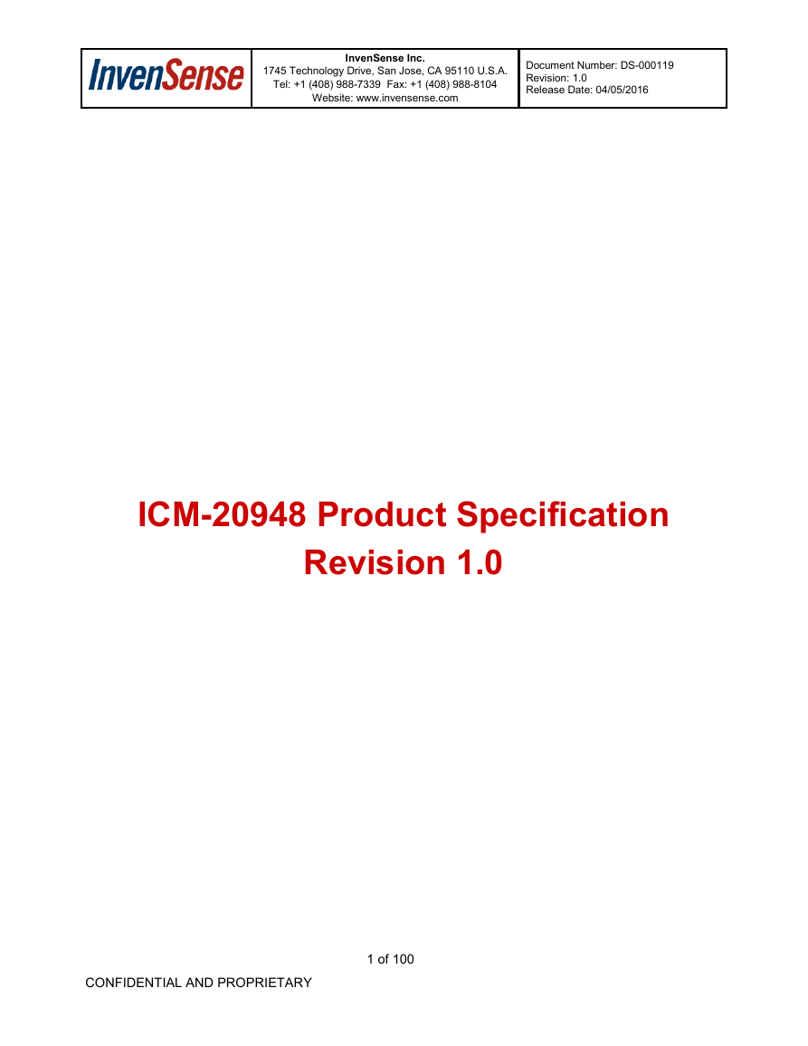
1745 Technology Drive, San Jose, CA 95110 U.S.A. Tel: +1 (408) 988-7339 Fax: +1 (408) 988-8104 InvenSense Inc. Website: www.invensense.com Document Number: DS-000119 Revision: 1.0 Release Date: 04/05/2016 ICM-20948 Product Specification Revision 1.0 CONFIDENTIAL AND PROPRIETARY 1 of 100
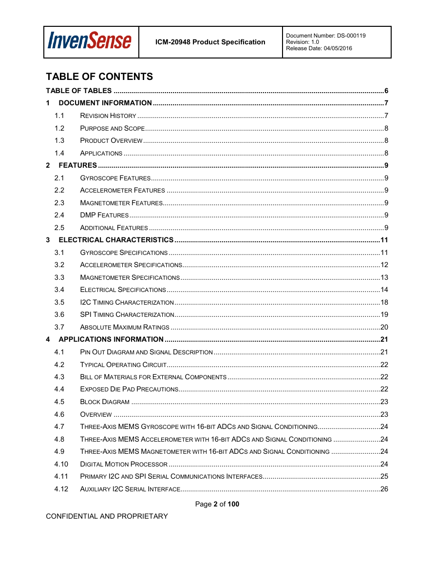
ICM-20948 Product Specification Document Number: DS-000119 Revision: 1.0 Release Date: 04/05/2016 1.1 1.2 1.3 1.4 2.1 2.2 2.3 2.4 2.5 TABLE OF CONTENTS TABLE OF TABLES .......................................................................................................................................... 6 1 DOCUMENT INFORMATION ...................................................................................................................... 7 REVISION HISTORY .............................................................................................................................. 7 PURPOSE AND SCOPE .......................................................................................................................... 8 PRODUCT OVERVIEW ........................................................................................................................... 8 APPLICATIONS ..................................................................................................................................... 8 2 FEATURES .................................................................................................................................................. 9 GYROSCOPE FEATURES ....................................................................................................................... 9 ACCELEROMETER FEATURES ............................................................................................................... 9 MAGNETOMETER FEATURES................................................................................................................. 9 DMP FEATURES .................................................................................................................................. 9 ADDITIONAL FEATURES ........................................................................................................................ 9 3 ELECTRICAL CHARACTERISTICS ......................................................................................................... 11 GYROSCOPE SPECIFICATIONS ............................................................................................................ 11 ACCELEROMETER SPECIFICATIONS ..................................................................................................... 12 MAGNETOMETER SPECIFICATIONS ...................................................................................................... 13 ELECTRICAL SPECIFICATIONS ............................................................................................................. 14 I2C TIMING CHARACTERIZATION ......................................................................................................... 18 SPI TIMING CHARACTERIZATION ......................................................................................................... 19 ABSOLUTE MAXIMUM RATINGS ........................................................................................................... 20 4 APPLICATIONS INFORMATION .............................................................................................................. 21 PIN OUT DIAGRAM AND SIGNAL DESCRIPTION ..................................................................................... 21 4.1 TYPICAL OPERATING CIRCUIT ............................................................................................................. 22 4.2 BILL OF MATERIALS FOR EXTERNAL COMPONENTS .............................................................................. 22 4.3 EXPOSED DIE PAD PRECAUTIONS....................................................................................................... 22 4.4 BLOCK DIAGRAM ............................................................................................................................... 23 4.5 OVERVIEW ........................................................................................................................................ 23 4.6 THREE-AXIS MEMS GYROSCOPE WITH 16-BIT ADCS AND SIGNAL CONDITIONING ................................ 24 4.7 THREE-AXIS MEMS ACCELEROMETER WITH 16-BIT ADCS AND SIGNAL CONDITIONING ........................ 24 4.8 4.9 THREE-AXIS MEMS MAGNETOMETER WITH 16-BIT ADCS AND SIGNAL CONDITIONING ......................... 24 4.10 DIGITAL MOTION PROCESSOR ............................................................................................................ 24 4.11 PRIMARY I2C AND SPI SERIAL COMMUNICATIONS INTERFACES ............................................................ 25 AUXILIARY I2C SERIAL INTERFACE...................................................................................................... 26 4.12 3.1 3.2 3.3 3.4 3.5 3.6 3.7 CONFIDENTIAL AND PROPRIETARY Page 2 of 100
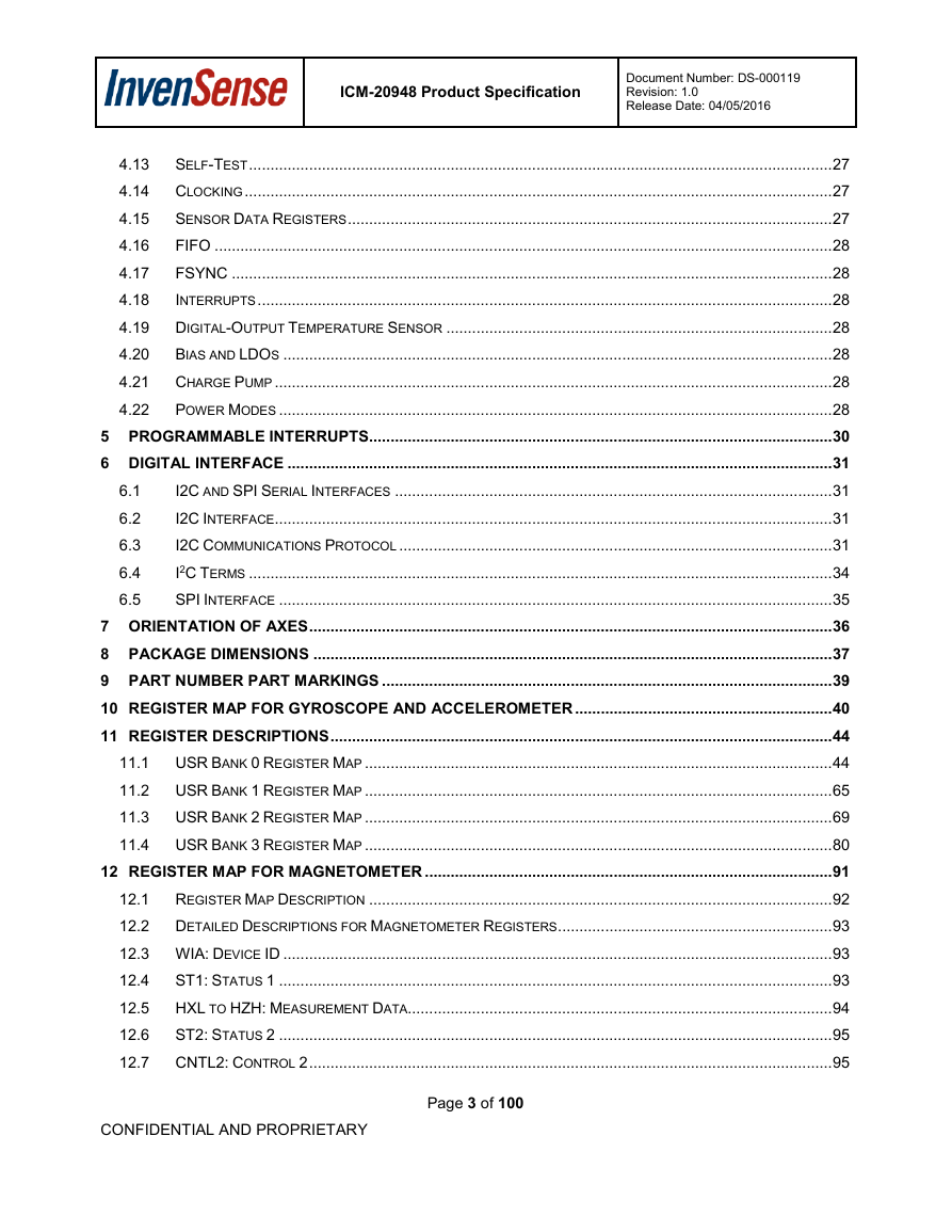
ICM-20948 Product Specification Document Number: DS-000119 Revision: 1.0 Release Date: 04/05/2016 6.1 6.2 6.3 6.4 6.5 4.13 SELF-TEST ........................................................................................................................................ 27 4.14 CLOCKING ......................................................................................................................................... 27 SENSOR DATA REGISTERS ................................................................................................................. 27 4.15 FIFO ................................................................................................................................................ 28 4.16 4.17 FSYNC ............................................................................................................................................ 28 4.18 INTERRUPTS ...................................................................................................................................... 28 4.19 DIGITAL-OUTPUT TEMPERATURE SENSOR .......................................................................................... 28 4.20 BIAS AND LDOS ................................................................................................................................ 28 4.21 CHARGE PUMP .................................................................................................................................. 28 4.22 POWER MODES ................................................................................................................................. 28 5 PROGRAMMABLE INTERRUPTS ............................................................................................................ 30 6 DIGITAL INTERFACE ............................................................................................................................... 31 I2C AND SPI SERIAL INTERFACES ...................................................................................................... 31 I2C INTERFACE .................................................................................................................................. 31 I2C COMMUNICATIONS PROTOCOL ..................................................................................................... 31 I2C TERMS ........................................................................................................................................ 34 SPI INTERFACE ................................................................................................................................. 35 7 ORIENTATION OF AXES .......................................................................................................................... 36 8 PACKAGE DIMENSIONS ......................................................................................................................... 37 9 PART NUMBER PART MARKINGS ......................................................................................................... 39 10 REGISTER MAP FOR GYROSCOPE AND ACCELEROMETER ............................................................ 40 11 REGISTER DESCRIPTIONS ..................................................................................................................... 44 11.1 USR BANK 0 REGISTER MAP ............................................................................................................. 44 11.2 USR BANK 1 REGISTER MAP ............................................................................................................. 65 11.3 USR BANK 2 REGISTER MAP ............................................................................................................. 69 11.4 USR BANK 3 REGISTER MAP ............................................................................................................. 80 12 REGISTER MAP FOR MAGNETOMETER ............................................................................................... 91 12.1 REGISTER MAP DESCRIPTION ............................................................................................................ 92 12.2 DETAILED DESCRIPTIONS FOR MAGNETOMETER REGISTERS ................................................................ 93 12.3 WIA: DEVICE ID ................................................................................................................................ 93 12.4 ST1: STATUS 1 ................................................................................................................................. 93 12.5 HXL TO HZH: MEASUREMENT DATA................................................................................................... 94 12.6 ST2: STATUS 2 ................................................................................................................................. 95 12.7 CNTL2: CONTROL 2 .......................................................................................................................... 95 CONFIDENTIAL AND PROPRIETARY Page 3 of 100
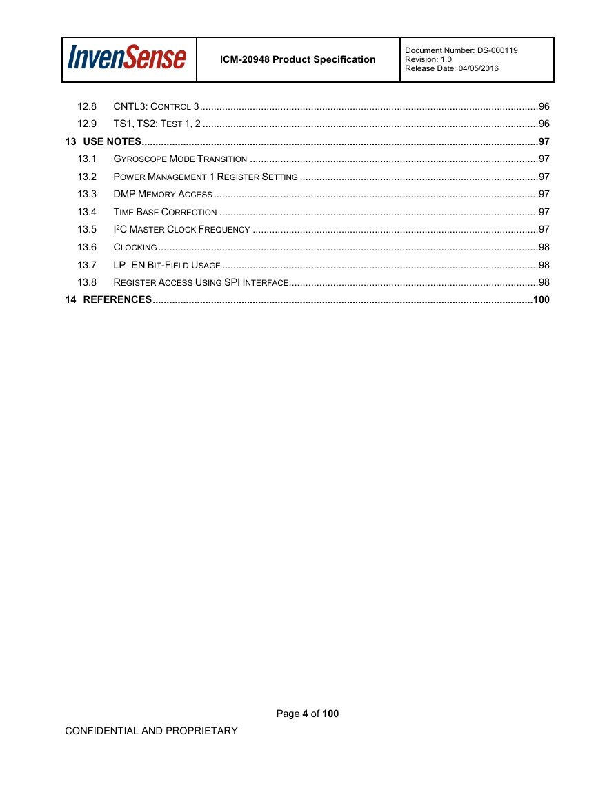
ICM-20948 Product Specification Document Number: DS-000119 Revision: 1.0 Release Date: 04/05/2016 12.8 CNTL3: CONTROL 3 .......................................................................................................................... 96 12.9 TS1, TS2: TEST 1, 2 ......................................................................................................................... 96 13 USE NOTES ............................................................................................................................................... 97 13.1 GYROSCOPE MODE TRANSITION ........................................................................................................ 97 13.2 POWER MANAGEMENT 1 REGISTER SETTING ...................................................................................... 97 13.3 DMP MEMORY ACCESS ..................................................................................................................... 97 13.4 TIME BASE CORRECTION ................................................................................................................... 97 13.5 I2C MASTER CLOCK FREQUENCY ....................................................................................................... 97 13.6 CLOCKING ......................................................................................................................................... 98 13.7 LP_EN BIT-FIELD USAGE .................................................................................................................. 98 13.8 REGISTER ACCESS USING SPI INTERFACE.......................................................................................... 98 14 REFERENCES ......................................................................................................................................... 100 CONFIDENTIAL AND PROPRIETARY Page 4 of 100
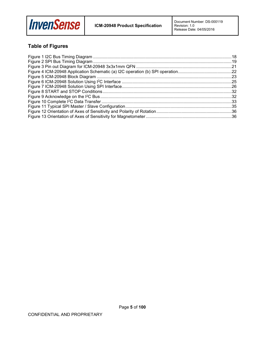
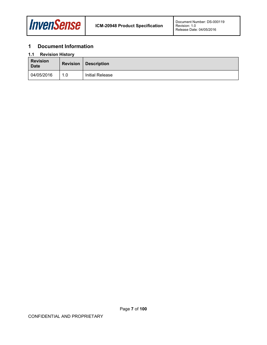
ICM-20948 Product Specification Document Number: DS-000119 Revision: 1.0 Release Date: 04/05/2016 Table of Figures Figure 1 I2C Bus Timing Diagram .................................................................................................................... 18 Figure 2 SPI Bus Timing Diagram .................................................................................................................... 19 Figure 3 Pin out Diagram for ICM-20948 3x3x1mm QFN ................................................................................ 21 Figure 4 ICM-20948 Application Schematic (a) I2C operation (b) SPI operation ............................................. 22 Figure 5 ICM-20948 Block Diagram ................................................................................................................. 23 Figure 6 ICM-20948 Solution Using I2C Interface ............................................................................................ 25 Figure 7 ICM-20948 Solution Using SPI Interface............................................................................................ 26 Figure 8 START and STOP Conditions ............................................................................................................ 32 Figure 9 Acknowledge on the I2C Bus .............................................................................................................. 32 Figure 10 Complete I2C Data Transfer ............................................................................................................. 33 Figure 11 Typical SPI Master / Slave Configuration ......................................................................................... 35 Figure 12 Orientation of Axes of Sensitivity and Polarity of Rotation ............................................................... 36 Figure 13 Orientation of Axes of Sensitivity for Magnetometer ........................................................................ 36 CONFIDENTIAL AND PROPRIETARY Page 5 of 100
ICM-20948 Product Specification Document Number: DS-000119 Revision: 1.0 Release Date: 04/05/2016 Table of Tables Table 1 Gyroscope Specifications .................................................................................................................... 11 Table 2 Accelerometer Specifications .............................................................................................................. 12 Table 3 Magnetometer Specifications .............................................................................................................. 13 Table 4 D.C. Electrical Characteristics ............................................................................................................. 14 Table 5 A.C. Electrical Characteristics ............................................................................................................. 16 Table 6 Other Electrical Specifications ............................................................................................................. 17 Table 7 I2C Timing Characteristics ................................................................................................................... 18 Table 8 SPI Timing Characteristics (7MHz) ..................................................................................................... 19 Table 9 Absolute Maximum Ratings ................................................................................................................. 20 Table 10 Signal Descriptions ............................................................................................................................ 21 Table 11 Bill of Materials .................................................................................................................................. 22 Table 12 Power Modes for ICM-20948 ............................................................................................................. 29 Table 13 Table of Interrupt Sources ................................................................................................................. 30 Table 14 Serial Interface ................................................................................................................................... 31 Table 15 I2C Terms ........................................................................................................................................... 34 Table 16 Register Table for Magnetometer ...................................................................................................... 91 Table 17 Register Map for Magnetometer ........................................................................................................ 92 Table 18 Magnetometer Measurement Data Format ....................................................................................... 94 CONFIDENTIAL AND PROPRIETARY Page 6 of 100
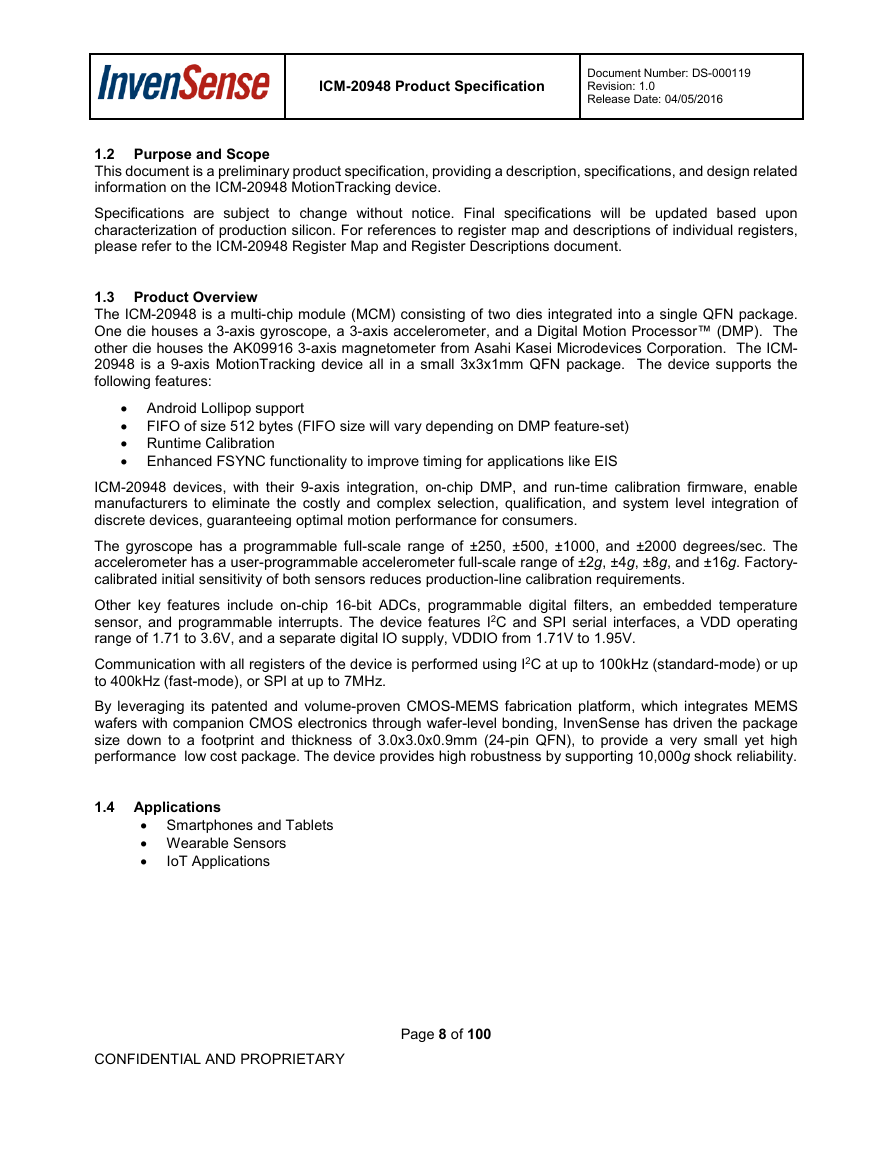
ICM-20948 Product Specification Document Number: DS-000119 Revision: 1.0 Release Date: 04/05/2016 1 Document Information 1.1 Revision History Revision Date 04/05/2016 1.0 Revision Description Initial Release CONFIDENTIAL AND PROPRIETARY Page 7 of 100
ICM-20948 Product Specification Document Number: DS-000119 Revision: 1.0 Release Date: 04/05/2016 1.2 Purpose and Scope This document is a preliminary product specification, providing a description, specifications, and design related information on the ICM-20948 MotionTracking device. Specifications are subject to change without notice. Final specifications will be updated based upon characterization of production silicon. For references to register map and descriptions of individual registers, please refer to the ICM-20948 Register Map and Register Descriptions document. 1.3 Product Overview The ICM-20948 is a multi-chip module (MCM) consisting of two dies integrated into a single QFN package. One die houses a 3-axis gyroscope, a 3-axis accelerometer, and a Digital Motion Processor™ (DMP). The other die houses the AK09916 3-axis magnetometer from Asahi Kasei Microdevices Corporation. The ICM- 20948 is a 9-axis MotionTracking device all in a small 3x3x1mm QFN package. The device supports the following features: Android Lollipop support FIFO of size 512 bytes (FIFO size will vary depending on DMP feature-set) • • • Runtime Calibration • Enhanced FSYNC functionality to improve timing for applications like EIS ICM-20948 devices, with their 9-axis integration, on-chip DMP, and run-time calibration firmware, enable manufacturers to eliminate the costly and complex selection, qualification, and system level integration of discrete devices, guaranteeing optimal motion performance for consumers. The gyroscope has a programmable full-scale range of ±250, ±500, ±1000, and ±2000 degrees/sec. The accelerometer has a user-programmable accelerometer full-scale range of ±2g, ±4g, ±8g, and ±16g. Factory- calibrated initial sensitivity of both sensors reduces production-line calibration requirements. Other key features include on-chip 16-bit ADCs, programmable digital filters, an embedded temperature sensor, and programmable interrupts. The device features I2C and SPI serial interfaces, a VDD operating range of 1.71 to 3.6V, and a separate digital IO supply, VDDIO from 1.71V to 1.95V. Communication with all registers of the device is performed using I2C at up to 100kHz (standard-mode) or up to 400kHz (fast-mode), or SPI at up to 7MHz. By leveraging its patented and volume-proven CMOS-MEMS fabrication platform, which integrates MEMS wafers with companion CMOS electronics through wafer-level bonding, InvenSense has driven the package size down to a footprint and thickness of 3.0x3.0x0.9mm (24-pin QFN), to provide a very small yet high performance low cost package. The device provides high robustness by supporting 10,000g shock reliability. 1.4 Applications Smartphones and Tablets • • Wearable Sensors • IoT Applications CONFIDENTIAL AND PROPRIETARY Page 8 of 100
分享到:
收藏