n
o
i
t
a
z
i
m
i
t
p
O
t
o
o
R
h
t
o
o
T
:
3
1
0
l
a
i
r
o
t
u
T
t
f
o
s
S
S
I
K
KISSsoft AG
Uetzikon 4
8634 Hombrechtikon
Switzerland
-
-
-
-
+41 55 254 20 50
+41 55 254 20 51
info@KISSsoft. AG
www. KISSsoft. AG
KISSsoft Tutorial: Tooth Root Optimization
1 Overview
1.1
Task
This tutorial shows how tooth root geometry influences tooth strength and how it can be
optimized. It recommends you use the "Graphical method" if you want to study the root strength
of non-standard root geometry.
To do this, you use the strength calculation and tooth geometry calculation.
1.2 Results
Three different root geometries are to be examined:
resulting root geometry, with a tool root radius factor *fP=0.38
resulting root geometry, with a tool root radius factor *fP=0.45
1.
2.
3. optimized root geometry (elliptical rounding)
The following results for safety factors are found when you use a combination of ISO 6336 and
ISO 6336 and the "Graphical method":
based
SF based on sizing
specified in ISO6336
on
sizing
SF
specified in ISO6336 with
the "Graphical method
2.5940
2.7584
2.7584*
6%*
2.4966
2.6756
2.8868
16%
Geometry 1 (fP=0.38)
Geometry 2 (fP=0.45)
Geometry 3 (elliptical)
Improvement from Geometry 1 to
Geometry 3
Table 1.1
Comparison of calculated safety factors for tooth root bending strength safety factors
depending on method
As you can clearly see, by optimizing the root geometry, the safety factor against bending
failure has been increased by 16%. However, this optimized root rounding requires a special
tool (modified cutter). For this reason, we recommend you use this method for mass production
(e.g. by form grinding) or if the gears are manufactured by wire erosion or sintering.
*Note: if you use the unmodified ISO 6336 method (or other methods like DIN 3990 or AGMA
2001) you cannot estimate a modified root geometry. You can see this because the results
from Geometry 2 to Geometry 3 do not change.
Theory
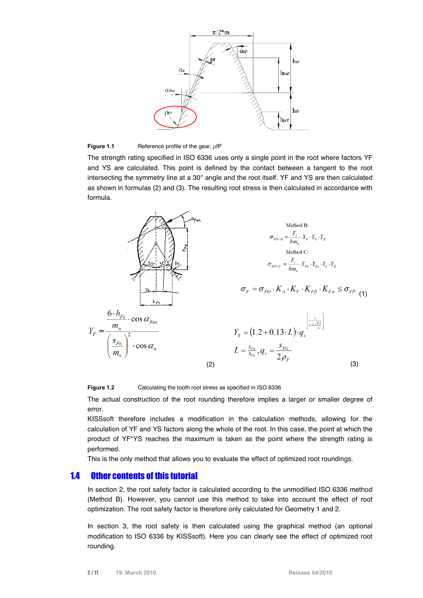
The value
fP is the radius of the root of the reference profile of the gear as shown below:
1.3
1 / 11
19. March 2010
Release 04/2010
�
Figure 1.1
Reference profile of the gear, fP
The strength rating specified in ISO 6336 uses only a single point in the root where factors YF
and YS are calculated. This point is defined by the contact between a tangent to the root
intersecting the symmetry line at a 30 angle and the root itself. YF and YS are then calculated
as shown in formulas (2) and (3). The resulting root stress is then calculated in accordance with
formula.
(2)
Calculating the tooth root stress as specified in ISO 6336
Figure 1.2
(1)
(3)
The actual construction of the root rounding therefore implies a larger or smaller degree of
error.
KISSsoft therefore includes a modification in the calculation methods, allowing for the
calculation of YF and YS factors along the whole of the root. In this case, the point at which the
product of YF*YS reaches the maximum is taken as the point where the strength rating is
performed.
This is the only method that allows you to evaluate the effect of optimized root roundings.
1.4 Other contents of this tutorial
In section 2, the root safety factor is calculated according to the unmodified ISO 6336 method
(Method B). However, you cannot use this method to take into account the effect of root
optimization. The root safety factor is therefore only calculated for Geometry 1 and 2.
In section 3, the root safety is then calculated using the graphical method (an optional
modification to ISO 6336 by KISSsoft). Here you can clearly see the effect of optimized root
rounding.
2 / 11
19. March 2010
Release 04/2010
�
The comparison between the calculated results is shown in Table 1.1
Further explanations and comments are given in section 4.
All calculations/changes are performed only for Gear 1.
2 Strength calculation as specified in ISO6336
2.1
For Geometry 1 (*fP=0.38)
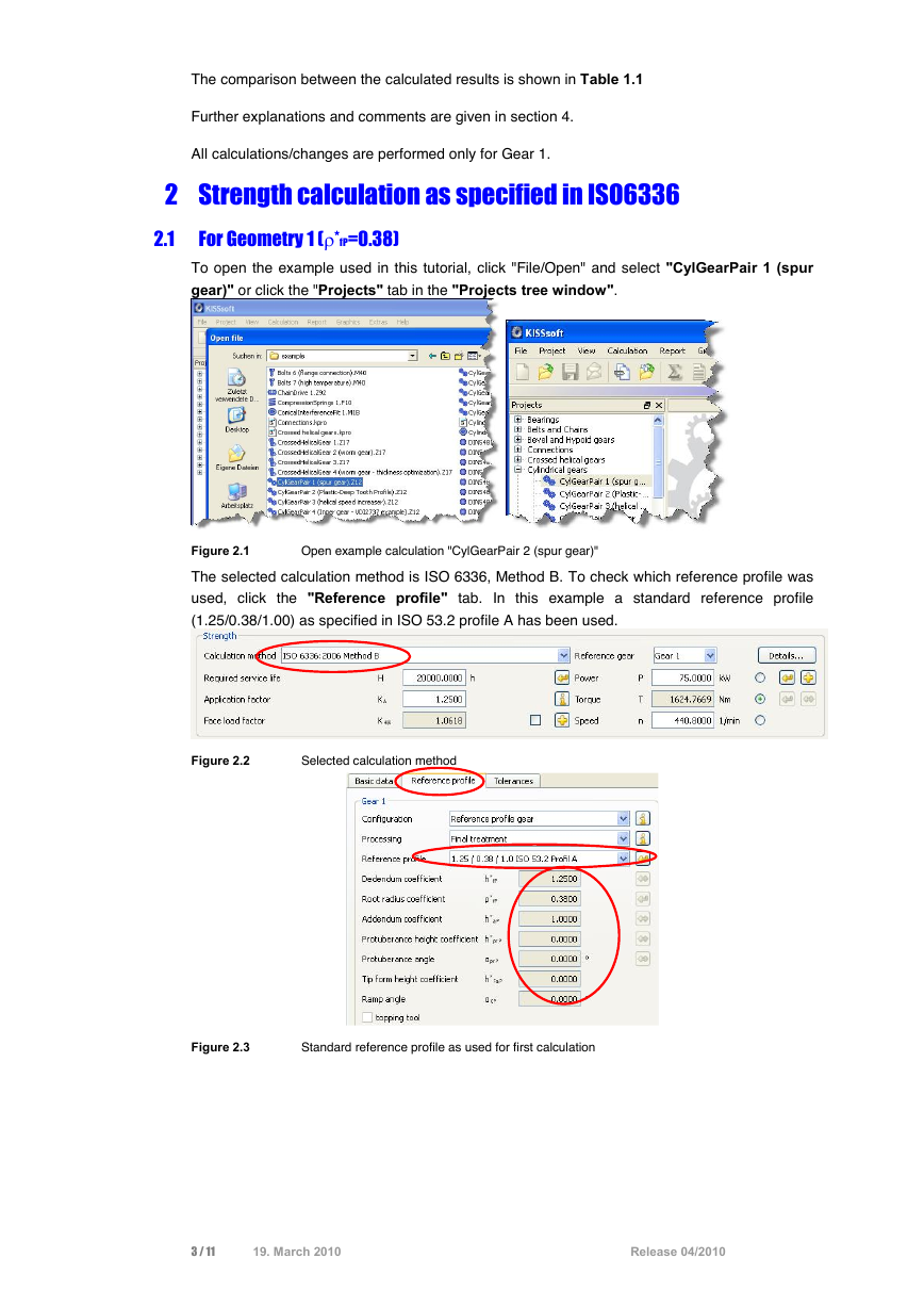
To open the example used in this tutorial, click "File/Open" and select "CylGearPair 1 (spur
gear)" or click the "Projects" tab in the "Projects tree window".
Figure 2.1
Open example calculation "CylGearPair 2 (spur gear)"
The selected calculation method is ISO 6336, Method B. To check which reference profile was
used, click the "Reference profile" tab. In this example a standard reference profile
(1.25/0.38/1.00) as specified in ISO 53.2 profile A has been used.
Figure 2.2
Selected calculation method
Figure 2.3
Standard reference profile as used for first calculation
3 / 11
19. March 2010
Release 04/2010
�
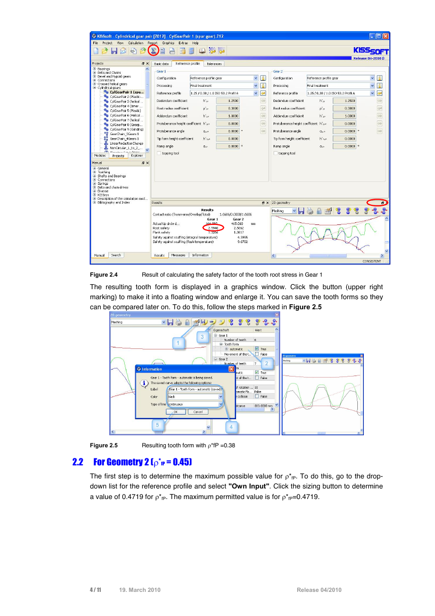
Figure 2.4
Result of calculating the safety factor of the tooth root stress in Gear 1
The resulting tooth form is displayed in a graphics window. Click the button (upper right
marking) to make it into a floating window and enlarge it. You can save the tooth forms so they
can be compared later on. To do this, follow the steps marked in Figure 2.5
2.2
Resulting tooth form with *fP =0.38
Figure 2.5
For Geometry 2 (*fP = 0.45)
The first step is to determine the maximum possible value for *fP. To do this, go to the drop-
down list for the reference profile and select "Own Input". Click the sizing button to determine
a value of 0.4719 for *fP. The maximum permitted value is for *fP=0.4719.
4 / 11
19. March 2010
Release 04/2010
�
Figure 2.6
Modification of *fP
This changes the input value for *fP. Input *fP=0.45. Now click
the calculation. No warning messages are issued here.
or press "F5" to perform
Figure 2.7
Result of root safety with changed *fP =0.45 for Gear 1
The safety factor of the root has been increased:
In the 2D graphic you can see both the old and new tooth form (use the "+"/"-" buttons to
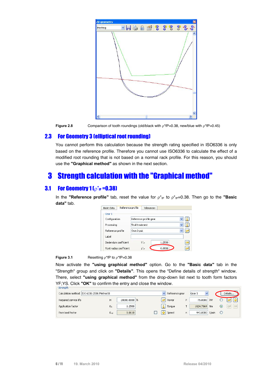
change its size). The blue curve is the tooth form generated with *fP=0.45. The black curve is
the old tooth form with *fP=0.38, that was saved previously.
5 / 11
19. March 2010
Release 04/2010
�
Figure 2.8
For Geometry 3 (elliptical root rounding)
Comparison of tooth roundings (old/black with *fP=0.38, new/blue with *fP=0.45)
2.3
You cannot perform this calculation because the strength rating specified in ISO6336 is only
based on the reference profile. Therefore you cannot use ISO6336 to calculate the effect of a
modified root rounding that is not based on a normal rack profile. For this reason, you should
use the "Graphical method" as shown in the next section.
3 Strength calculation with the "Graphical method"
3.1
For Geometry 1 (*fP =0.38)
In the "Reference profile" tab, reset the value for *fP to *fP=0.38. Then go to the "Basic
data" tab.
Resetting *fP to *fP=0.38
Figure 3.1
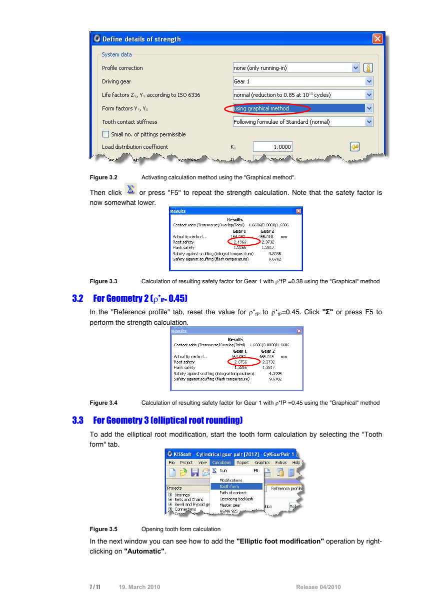
Now activate the "using graphical method" option. Go to the "Basic data" tab in the
"Strength" group and click on "Details". This opens the "Define details of strength" window.
There, select "using graphical method" from the drop-down list next to tooth form factors
YF;YS. Click "OK" to confirm the entry and close the window.
6 / 11
19. March 2010
Release 04/2010
�
Figure 3.2
Activating calculation method using the "Graphical method".
Then click
now somewhat lower.
or press "F5" to repeat the strength calculation. Note that the safety factor is
3.2
Calculation of resulting safety factor for Gear 1 with *fP =0.38 using the "Graphical" method
Figure 3.3
For Geometry 2 (*fP= 0.45)
In the "Reference profile" tab, reset the value for *fP to *fP=0.45. Click "" or press F5 to
perform the strength calculation.
Figure 3.4
Calculation of resulting safety factor for Gear 1 with *fP =0.45 using the "Graphical" method
3.3 For Geometry 3 (elliptical root rounding)
To add the elliptical root modification, start the tooth form calculation by selecting the "Tooth
form" tab.
Opening tooth form calculation
Figure 3.5
In the next window you can see how to add the "Elliptic foot modification" operation by right-
clicking on "Automatic".
7 / 11
19. March 2010
Release 04/2010
�
Figure 3.6
Adding the elliptical root modification
to the right of the "Modification from diameter" field to define where the
Then click
elliptical root modification is to start. Click the right-hand mouse button on the "Elliptic root
modification" icon and select "Choose as result" to ensure that this tooth is modified.
Starting the modification, activating the calculation step
Figure 3.7
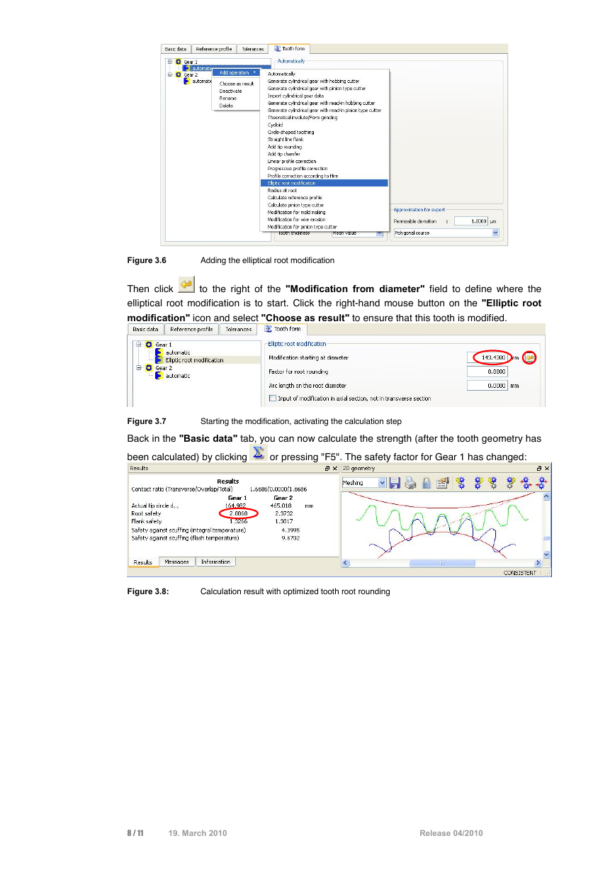
Back in the "Basic data" tab, you can now calculate the strength (after the tooth geometry has
been calculated) by clicking
or pressing "F5". The safety factor for Gear 1 has changed:
Figure 3.8:
Calculation result with optimized tooth root rounding
8 / 11
19. March 2010
Release 04/2010
�



 2023年江西萍乡中考道德与法治真题及答案.doc
 2012年重庆南川中考生物真题及答案.doc
 2013年江西师范大学地理学综合及文艺理论基础考研真题.doc
 2020年四川甘孜小升初语文真题及答案I卷.doc
 2020年注册岩土工程师专业基础考试真题及答案.doc
 2023-2024学年福建省厦门市九年级上学期数学月考试题及答案.doc
 2021-2022学年辽宁省沈阳市大东区九年级上学期语文期末试题及答案.doc
 2022-2023学年北京东城区初三第一学期物理期末试卷及答案.doc
 2018上半年江西教师资格初中地理学科知识与教学能力真题及答案.doc
 2012年河北国家公务员申论考试真题及答案-省级.doc
 2020-2021学年江苏省扬州市江都区邵樊片九年级上学期数学第一次质量检测试题及答案.doc
 2022下半年黑龙江教师资格证中学综合素质真题及答案.doc