SIMULIA Tosca Structure Documentation 8.1
Table of Contents
General Remarks
Start Manual
Preface
1 Getting Started with Tosca ANSA environment
1.1 User Interface
1.1.1 General Buttons toolbar
1.1.1.1 FOCUS panel
1.1.1.2 VISIBILITY panel
1.1.2 Database and selection windows
1.1.3 Task Manager window
1.1.4 Input of an existing parameter file
1.1.5 Saving task and saving database
1.1.6 Highlighting
1.1.7 Input and output using Task Manager
1.1.8 Input and output using the main menu
1.1.9 Modules Buttons window
1.1.10 Selecting and deselecting the geometric objects
1.1.10.1 Selecting single objects
1.1.10.2 Box selection
1.1.10.3 Polygon area selection
1.1.11 View control
1.1.11.1 Rotating
1.1.11.2 Translating
1.1.11.3 Zooming
1.1.11.4 Faster view selection
1.1.11.5 Function keys related to view control
1.1.12 Keys facilitating input in dialogs
1.1.13 Managing Groups
1.1.13.1 SET HELP window
1.1.13.2 Selection of objects in group selection mode
1.1.13.3 List of Tosca Structure commands with groups
1.1.14 Configuration of Tosca ANSA environment
1.2 Topology Optimization with Tosca ANSA environment
1.2.1 What is Topology Optimization?
1.2.2 The Model
1.2.3 Optimization Task
1.2.4 Step by Step Manual: Summary
1.2.5 Preprocessing
1.2.5.1 Choice of the optimization type
1.2.5.2 Loading the input model file
1.2.5.3 Choice of the design area
1.2.5.4 Choice of the design constraints
1.2.5.5 Choice of the objective function
1.2.5.6 Choice of the constraints
1.2.5.7 Saving Tosca Structure parameter file
1.2.6 Start Optimization
1.2.6.1 Start Tosca Structure
1.2.6.2 Logging and monitoring
1.2.7 Postprocessing
1.2.8 Report Generation
1.2.9 Result Transfer and Validation Run (Smooth)
1.2.9.1 Generating smooth surface
1.2.9.2 Modifying the surface using RECONSTRUCT
1.2.9.3 Remeshing the model
1.2.9.4 Saving the resulting model in solver format
1.2.9.5 Running the solver with the new model
1.2.9.6 Saving the resulting model in solver format (alternative)
1.2.9.7 Running the solver with the new model (alternative)
1.2.10 Result Discussion
1.3 Shape Optimization with Tosca ANSA environment
1.3.1 What is Shape Optimization?
1.3.2 The Model
1.3.3 Optimization Task
1.3.4 Step by Step Manual: Summary
1.3.5 Preprocessing
1.3.5.1 Choice of the optimization type
1.3.5.2 Loading the input model file
1.3.5.3 Selection of mesh smoothing elements
1.3.5.4 Choice of design area
1.3.5.5 Choice of design variable constraint
1.3.5.6 Choice of the objective function
1.3.5.7 Saving Tosca Structure parameter file
1.3.6 Node Displacement Check (Check Inputs)
1.3.7 Start Optimization
1.3.7.1 Start Tosca Structure
1.3.7.2 Logging and monitoring
1.3.7.3 Viewing the results in the optimized model
1.3.8 Postprocessing
1.3.9 Report Generation
1.3.10 Result transfer (Smooth)
1.3.10.1 Generating smooth surface
1.3.11 Result Discussion
1.3.12 Extensions
1.3.12.1 Design variable constraints
1.3.12.2 Define a volume constraint
1.3.12.3 Redefine the global stop condition
1.3.12.4 Selecting mesh smooth elements automatically
1.3.13 Troubleshooting
1.3.13.1 Suggestions in case of mesh problems
1.4 Bead Optimization with Tosca ANSA environment
1.4.1 What is Bead Optimization?
1.4.1.1 Tosca Structure.bead
1.4.2 The Model
1.4.3 Optimization Task
1.4.4 Step by Step Manual: Summary
1.4.5 Preprocessing
1.4.5.1 Choice of the optimization type
1.4.5.2 Loading the input model file
1.4.5.3 Choice of design area
1.4.5.4 Choice of the objective function
1.4.5.5 Choice of the constraint
1.4.5.6 Optimization settings
1.4.5.7 Saving Tosca Structure parameter file
1.4.6 Node Displacement Check (Check Inputs)
1.4.7 Start Optimization
1.4.7.1 Start Tosca Structure
1.4.7.2 Logging and monitoring
1.4.7.3 Viewing the results in the optimized model
1.4.8 Postprocessing
1.4.9 Report Generation
1.4.10 Result Transfer (Smooth)
1.4.10.1 Generating smooth surface
1.4.11 Result Discussion
1.5 Sizing with Tosca ANSA environment
1.5.1 What is Sizing Optimization?
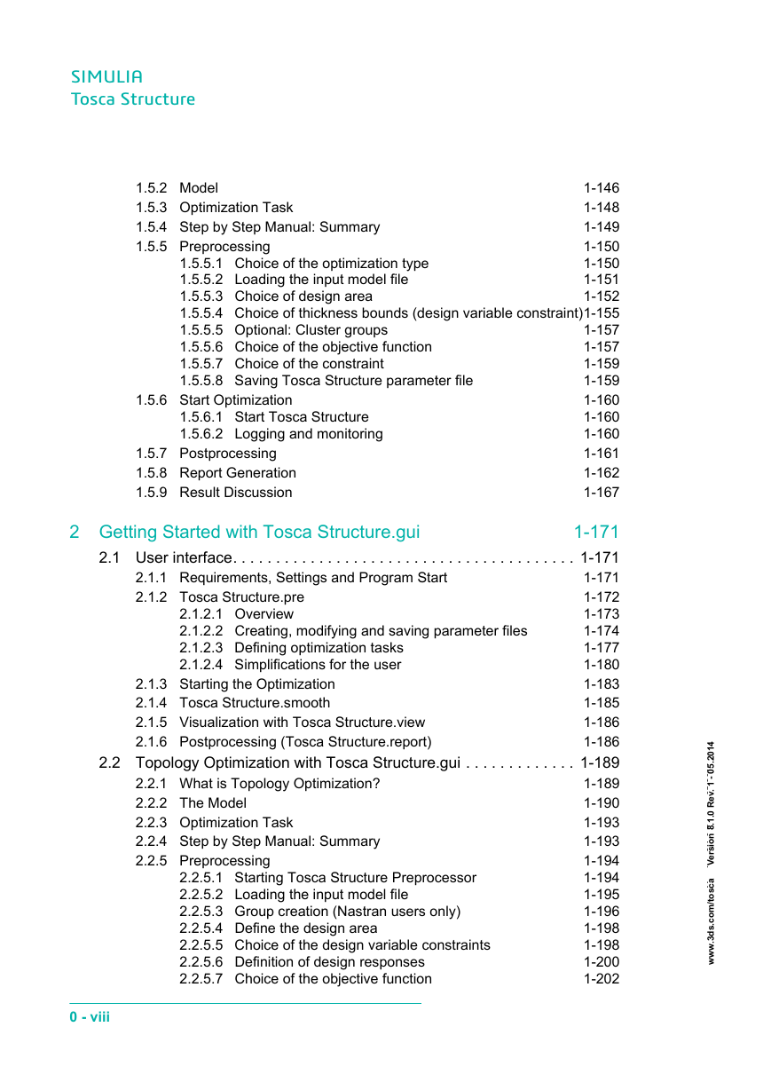
1.5.2 Model
1.5.3 Optimization Task
1.5.4 Step by Step Manual: Summary
1.5.5 Preprocessing
1.5.5.1 Choice of the optimization type
1.5.5.2 Loading the input model file
1.5.5.3 Choice of design area
1.5.5.4 Choice of thickness bounds (design variable constraint)
1.5.5.5 Optional: Cluster groups
1.5.5.6 Choice of the objective function
1.5.5.7 Choice of the constraint
1.5.5.8 Saving Tosca Structure parameter file
1.5.6 Start Optimization
1.5.6.1 Start Tosca Structure
1.5.6.2 Logging and monitoring
1.5.7 Postprocessing
1.5.8 Report Generation
1.5.9 Result Discussion
2 Getting Started with Tosca Structure.gui
2.1 User interface
2.1.1 Requirements, Settings and Program Start
2.1.2 Tosca Structure.pre
2.1.2.1 Overview
2.1.2.2 Creating, modifying and saving parameter files
2.1.2.3 Defining optimization tasks
2.1.2.4 Simplifications for the user
2.1.3 Starting the Optimization
2.1.4 Tosca Structure.smooth
2.1.5 Visualization with Tosca Structure.view
2.1.6 Postprocessing (Tosca Structure.report)
2.2 Topology Optimization with Tosca Structure.gui
2.2.1 What is Topology Optimization?
2.2.2 The Model
2.2.3 Optimization Task
2.2.4 Step by Step Manual: Summary
2.2.5 Preprocessing
2.2.5.1 Starting Tosca Structure Preprocessor
2.2.5.2 Loading the input model file
2.2.5.3 Group creation (Nastran users only)
2.2.5.4 Define the design area
2.2.5.5 Choice of the design variable constraints
2.2.5.6 Definition of design responses
2.2.5.7 Choice of the objective function
2.2.5.8 Choice of the constraints
2.2.5.9 Definition of the optimization task
2.2.5.10 Saving Tosca Structure parameter file
2.2.6 Start Optimization
2.2.7 Postprocessing
2.2.8 Report Generation
2.2.9 Result Transfer and Validation Run
2.2.9.1 Surface generation using Tosca Structure.smooth.
2.2.9.2 Processing the optimized structure
2.2.10 Result Discussion
2.3 Shape Optimization with Tosca Structure.gui
2.3.1 What is Shape Optimization?
2.3.2 The Model
2.3.3 Optimization Task
2.3.4 Step by Step Manual: Summary
2.3.5 Preprocessing
2.3.5.1 Starting Tosca Structure Preprocessor
2.3.5.2 Loading the input model file
2.3.5.3 Group creation (Nastran users only)
2.3.5.4 Select design area
2.3.5.5 Definition of design responses
2.3.5.6 Choice of the design variable constraint
2.3.5.7 Choice of the objective function
2.3.5.8 Select mesh smoothing elements
2.3.5.9 Definition of the optimization task
2.3.5.10 Define a stop condition
2.3.5.11 Saving Tosca Structure parameter file
2.3.6 Check Inputs
2.3.6.1 TEST_SHAPE
2.3.6.2 Starting the test optimization
2.3.6.3 Viewing the test results
2.3.7 Start Optimization
2.3.8 Postprocessing
2.3.9 Report Generation
2.3.10 Result Transfer
2.3.11 Result Discussion
2.3.12 Extensions
2.3.12.1 Design variable constraints
2.3.12.2 Define a volume constraint
2.3.12.3 Updating the optimization task
2.3.12.4 Redefine the global stop condition
2.3.12.5 Selecting mesh smooth elements automatically
2.3.13 Troubleshooting
2.3.13.1 How to workaround mesh problems?
2.4 Bead Optimization with Tosca Structure.gui
2.4.1 What is Bead Optimization?
2.4.1.1 Tosca Structure.bead
2.4.2 Model
2.4.3 Optimization Task
2.4.4 Step by Step Manual: Summary
2.4.5 Preprocessing
2.4.5.1 Starting Tosca Structure Preprocessor
2.4.5.2 Loading the input model file
2.4.5.3 Group creation (Nastran users only)
2.4.5.4 Select design area
2.4.5.5 Definition of design responses
2.4.5.6 Choice of the objective function
2.4.5.7 Create bead height constraint
2.4.5.8 Definition of the optimization task
2.4.5.9 Optimization settings
2.4.5.10 Saving Tosca Structure parameter file
2.4.6 Check Inputs
2.4.6.1 TEST_BEAD
2.4.6.2 Starting the test optimization
2.4.6.3 Viewing test results
2.4.7 Start Optimization
2.4.8 Postprocessing
2.4.8.1 Result Transfer
2.4.9 Report Generation
2.4.10 Result Discussion
2.4.10.1 Logging and monitoring
2.5 Sizing Optimization with Tosca Structure.gui
2.5.1 What is Sizing Optimization?
2.5.2 Model
2.5.3 Optimization Task
2.5.4 Step by Step Manual: Summary
2.5.5 Preprocessing
2.5.5.1 Starting Tosca Structure Preprocessor
2.5.5.2 Loading the input model file
2.5.5.3 Define the design area
2.5.5.4 Choice of thickness bounds (design variable constraint)
2.5.5.5 Optional: Cluster groups
2.5.5.6 Definition of design responses
2.5.5.7 Choice of the objective function
2.5.5.8 Choice of the constraints
2.5.5.9 Definition of the optimization task
2.5.5.10 Saving Tosca Structure parameter file
2.5.6 Start Optimization
2.5.7 Postprocessing
2.5.8 Report Generation
2.5.9 Result Discussion
3 Getting Started with Tosca Extension for ANSYS/WB
3.1 User Interface
3.1.1 Buttons
3.1.2 Handling Tips
3.2 Topology Optimization with Tosca Extension for ANSYS/WB
3.2.1 The model
3.2.2 Loading the Extension
3.2.3 Example files
3.2.4 Preparing the model
3.2.5 Optimization preprocessing
3.2.6 Postprocessing
3.2.6.1 Optimization result view options
3.2.6.2 Iteration Animation
3.2.7 Validation Run
3.2.8 Troubleshooting
3.3 Shape Optimization with Tosca Extension for ANSYS/WB
3.3.1 The model
3.3.2 Loading the extension
3.3.3 Example files
3.3.4 Preparing the model
3.3.5 Optimization preprocessing
3.3.6 Postprocessing
3.3.6.1 Optimization result view options
3.3.6.2 Iteration Animation
3.3.7 Troubleshooting
User Manual
Preface
1 Overview of Tosca Structure
1.1 The Tosca Structure Modules
1.1.1 Abaqus CAE
1.1.2 Tosca ANSA environment
1.1.3 Tosca Structure.gui
1.1.4 Tosca Extension for ANSYS/WB
1.1.5 Tosca Structure optimization modules
1.1.6 Tosca Structure.report
1.1.7 Tosca Structure.view
1.1.8 Tosca Structure.smooth
1.2 Overview of the Optimization Process
1.2.1 Planning
1.2.2 Preprocessing: Model generation
1.2.3 Check Run
1.2.4 Optimization Loop
1.2.5 Postprocessing: Evaluation of Optimization results
1.2.6 Result Transfer and Validation Run
1.3 Workflow for Optimization
2 Working with Tosca Structure
2.1 Working with Tosca ANSA environment
2.1.1 Preprocessing
2.1.2 Check Run
2.1.3 Start Optimization
2.1.4 Postprocessing
2.1.5 Result Transfer and Validation Run
2.2 Working with the Graphical User Interface Tosca Structure.gui
2.2.1 Preprocessing
2.2.2 Check Run
2.2.3 Start Optimization
2.2.4 Postprocessing
2.2.5 Result Transfer and Validation Run
2.3 Working with Tosca Extension for ANSYS/ Workbench
2.3.1 Preprocessing
2.3.2 Start Optimization
2.3.3 Postprocessing
2.3.4 Result Transfer and Validation Run
2.4 Working with Tosca Structure in the Command Shell
2.4.1 Logging in command shell
2.4.2 Preprocessing
2.4.3 Check Run
2.4.4 Start optimization
2.4.5 Postprocessing
2.4.6 Result Transfer
3 The Model
3.1 Models for Optimization
3.1.1 Models for topology optimization
3.1.2 Models for shape optimization
3.1.3 Models for bead optimization
3.1.4 Models for sizing
3.2 Optimizable Element Types
3.3 Preprocessing FE Models for Optimization
3.3.1 Abaqus/CAE
3.3.2 Preprocessing with ANSYS/Prep7
3.3.2.1 Generation of the finite element input file
3.3.2.2 Load cases
3.3.2.3 Check of the batch input file
3.3.2.4 Generation of groups
3.3.3 Preprocessing with ANSYS Workbench
3.3.3.1 Export of finite element input model
3.3.3.2 Generation of groups
3.3.3.3 Suitable meshes for topology optimization
3.4 Loading FE Data
3.4.1 Analysis Files for Optimization (FEM_INPUT)
3.4.2 LIFE_FILE
3.4.3 TEMPERATURE_FILE
3.4.4 ADD_FILE
3.4.5 COPY_FILE
3.4.6 Special FEM_INPUT-commands
3.4.7 Options for loading FE Data (OPTIONS)
3.4.7.1 Loading displacement restrictions
3.4.7.2 Identifying surface nodes for shape optimization
3.5 Include Files
3.6 Group Definition (GROUP_DEF, GROUP_AUTO_DEF)
3.6.1 Default predefined groups
3.6.2 Group definition in Tosca ANSA environment
3.6.3 Group definition in Tosca Extension for ANSYS/WB
3.6.4 Manual group definition in Tosca Structure.gui
3.6.5 Automatic node group definition (GROUP_AUTO_DEF)
3.7 Selection of Objects in Tosca Structure.gui
3.8 Coordinate Systems (CS_DEF)
3.8.1 Definition by three nodes
3.8.2 Definition by coordinates of three points
3.8.3 Definition by origin and rotation angles
3.8.4 General remarks about coordinate systems
3.9 Solids (Geometric Primitives)
3.9.1 Definition in Tosca ANSA environment
3.9.2 Definition in Tosca Structure.gui
4 Terms for Optimization
4.1 Overview
4.1.1 Mathematical formulation
4.2 Objective Function
4.2.1 Overview
4.2.2 Minimization or maximization of an objective function
4.2.3 Multidisciplinary objectives (minmax formulation)
4.3 Constraints
4.4 Design Responses
4.4.1 Compliance (Stiffness Optimization)
4.4.1.1 Compliance example
4.4.2 Energy stiffness measure
4.4.2.1 Example for energy stiffness measure
4.4.3 Displacement and rotation
4.4.3.1 Example of a displacement design response
4.4.4 Reaction force
4.4.4.1 Example of reaction force design response
4.4.5 Internal force
4.4.5.1 Example internal force
4.4.6 Eigenfrequency
4.4.6.1 Eigenvalue example
4.4.6.2 Mode tracking
4.4.7 Equivalent stress
4.4.8 Stress in topology optimization
4.4.8.1 Example: Stresses in objective function
4.4.8.2 Example: Stresses in constraint definition
4.4.9 Center of gravity
4.4.10 Moment of inertia
4.4.11 Volume
4.4.11.1 Volume design response example
4.4.12 Weight
4.4.12.1 Example of a weight design response
4.4.13 DENSITY_MEASURE
4.4.14 Bead height
4.5 Combined Terms
4.5.1 Group operations for design responses
4.5.1.1 Group Operations for Stresses
4.5.1.2 Group Operations for Stiffness
4.5.1.3 Group Operations for Displacements
4.5.1.4 Group operations for reaction forces/moments
4.5.1.5 Group Operations for Internal Forces
4.5.2 Load case combination and selection
4.5.2.1 Load case specification (LC_SET)
4.5.2.2 Selection criteria for load cases (LC_SEL)
4.5.3 Design response combination
4.5.3.1 Combined responses in sensitivity based optimization
4.5.3.2 Combining design responses (Tosca ANSA environment)
4.5.3.3 Combining displacements and rotations
4.5.3.4 Combining reaction forces and internal forces
4.5.3.5 Combining absolute values of responses
4.5.3.6 Controller based combined terms
4.5.3.7 Other operators for controller based shape optimization
4.6 Logging and Monitoring
5 Topology Optimization
5.1 General Information
5.2 The Optimization Task
5.2.1 Controller versus sensitivity based topology optimization
5.2.2 How to create the optimization model
5.3 Design Area
5.3.1 Design variables
5.3.1.1 Results from previous runs as initial material distribution
5.3.2 Manufacturing conditions and geometrical restrictions
5.3.2.1 Frozen areas
5.3.2.2 Prevention of undercuts in the model
5.3.2.3 Tightness constraint for the resulting structure
5.3.2.4 Stamping restriction
5.3.2.5 Minimum truss thickness (minimum member size)
5.3.2.6 Maximum truss thickness (maximum member size)
5.3.2.7 Symmetry conditions
5.3.2.8 Combination of manufacturing restrictions
5.3.2.9 Tips on defining restrictions with Tosca Structure.gui
5.4 Objective Function
5.4.1 Overview
5.4.2 Minimization or maximization of an objective
5.4.3 Multidisciplinary objective (minmax formulation)
5.5 Constraints
5.5.1 Multiple material constraints and constitutive laws
5.6 Typical Tasks for Static Analysis
5.6.1 Minimizing compliance under volume constraint
5.6.2 Minimizing displacement/rotation under volume constraint
5.6.3 Constraint for difference between two displacements
5.6.4 Minimization of a reaction or internal force
5.6.5 Minimization of the volume under displacement constraint
5.6.6 Minimize the maximum stress with volume constraint
5.6.7 Minimize the material volume with stress constraint
5.7 Typical Optimization Tasks for Modal Analysis
5.7.1 Maximization of the first eigenfrequencies
5.7.2 Maximizing the eigenfrequency of a certain eigenmode
5.7.3 Maximization of the band gap
5.7.4 Constraining an eigenfrequency
5.8 Settings
5.8.1 Parameters for standard linear static topology optimization
5.8.1.1 Increments of volume modification (SPEED)
5.8.1.2 Volume reduction in first iteration (START_DELETE)
5.8.1.3 Tips on speed control
5.8.1.4 Relation between relative density and stiffness
5.8.2 Settings for the general sensitivity based optimization
5.8.2.1 Mode tracking
5.8.2.2 Initial values of density
5.8.2.3 Removing soft elements for increasing performance
5.8.2.4 Limits for design variables and changes
5.8.2.5 Update strategy of the method of moving asymptotes
5.8.2.6 Settings of the mesh filter
5.8.2.7 FILTER_TYPE
5.8.2.8 Material interpolation
5.9 Stop Condition
5.9.1 Convergence Criteria
5.9.1.1 Stop criterion: change in objective function
5.9.1.2 Stop criterion: change in element densities
5.9.1.3 Start iteration for convergence check
5.9.2 Global Stop Criterion (Number of iterations)
5.10 References
6 Shape Optimization
6.1 General Information
6.1.1 Theoretical background
6.2 The Optimization Task
6.2.1 How to create the optimization model
6.3 Design Area
6.3.1 Design variables (DV_SHAPE)
6.3.2 Mesh smoothing (MESH_SMOOTH)
6.3.2.1 Element group for mesh smoothing
6.3.2.2 Fixation of free surface nodes (FREE_SF)
6.3.2.3 Fixation of the MESH_SMOOTH area boundary
6.3.2.4 Automatic MESH_SMOOTH area (MS_LAYER)
6.3.2.5 Convergence of the smoothed mesh (LEVEL_CONV)
6.3.2.6 Enforcing restrictions (LEVEL_DVCON)
6.3.2.7 Quality control and improvement (LEVEL_QUAL)
6.3.2.8 Quality criteria of the solver (SOLVER_CHECK)
6.3.2.9 Correction of distorted elements (CORRECT_ELEMENTS)
6.3.2.10 Mesh smooth strategy (STRATEGY)
6.3.2.11 Definition in Tosca ANSA environment
6.3.3 Restrictions (DVCON_SHAPE)
6.3.3.1 Node group for design variable constraints
6.3.3.2 Restricting the amount of displacement
6.3.3.3 Minimum or maximum member size
6.3.3.4 Displacement check against solids (CHECK_SOLID)
6.3.3.5 Penetration check (CHECK_ELGR, PENETRATION_CHECK)
6.3.3.6 Restricting displacement directions (CHECK_BC, CHECK_DOF)
6.3.3.7 Restricting displacement to a slide surface
6.3.3.8 Assigning link/coupling conditions (CHECK_LINK)
6.3.3.9 Definition in Tosca ANSA environment
6.3.3.10 Definition in Tosca Structure.gui
6.3.3.11 Command syntax
6.3.4 Link and coupling conditions (LINK_SHAPE)
6.3.4.1 Determining the master node (MASTER)
6.3.4.2 Displacement of the client nodes (CLIENT)
6.3.4.3 Plane symmetry (PLANE_SYM)
6.3.4.4 Plane symmetry for non-symmetric meshes (SURF_PLANE_SYM)
6.3.4.5 Cyclic symmetry for non-symmetric meshes (SURF_CYCLIC_SYM)
6.3.4.6 Cyclic-plane symmetry combination (SURF_CYCLIC_PLANE_SYM)
6.3.4.7 Point symmetry (POINT_SYM)
6.3.4.8 Rotational symmetry (ROTATION_SYM)
6.3.4.9 Coupling displacement coordinates (VECTOR)
6.3.4.10 Coupling displacement direction (DIRECTION)
6.3.4.11 Coupling amount of displacement (LENGTH)
6.3.4.12 Coupling coordinates in the FE displacement coordinate system (DISP_CS)
6.3.4.13 Stampable surface (SURF_STAMP)
6.3.4.14 Turnable surface (SURF_TURN)
6.3.4.15 Drillable surface (SURF_DRILL)
6.3.4.16 Demoldable surface (SURF_DEMOLD)
6.3.4.17 Command examples
6.4 Objective Function
6.4.1 Overview
6.4.2 Reference stress
6.4.3 Objective function terms
6.5 Constraints
6.5.1 Volume constraint
6.5.2 Weight constraint
6.6 Typical Optimization Tasks for Static Analysis
6.6.1 Minimization of maximum equivalent stress
6.6.2 Notch optimization with fixed reference value
6.6.3 Notch relief with variable reference value
6.7 Advanced Tosca Structure.shape Optimizations
6.7.1 Highly nonlinear shape optimization
6.7.2 Minimization of contact pressure
6.8 Settings
6.8.1 Scale of displacement (SCALE)
6.8.2 Treatment of the midside nodes (MID_NODES)
6.8.3 Curvature based modification of optimization displacements
6.8.4 Filter function for the optimization displacements (FILTER)
6.8.5 Updating the optimization displacement vectors (VECTOR)
6.8.6 Control of the amount of optimization displacement (DISP)
6.9 Check run (TEST_SHAPE)
6.9.1 General
6.9.2 Test run (CHECK_INPUTS) in Tosca ANSA environment
6.9.3 Test run in Tosca Structure.gui
6.9.4 Command syntax
6.10 Morphing
6.10.1 General
6.10.1.1 Morphing areas
6.10.1.2 Morphing displacement
6.10.1.3 Morphing task
6.10.2 Morphing in Tosca ANSA environment
6.10.3 Morphing in Tosca Structure.gui
6.10.4 Command Syntax
6.10.5 Postprocessing
6.10.6 Evaluation
6.11 Stop Condition
6.11.1 Global Stop Condition
6.11.2 Local Stop Condition
6.11.3 Stop Condition in Tosca ANSA environment
6.11.4 Stop Condition in Tosca Structure.gui
6.11.5 Examples
6.12 References
7 Bead Optimization
7.1 General Information
7.2 The Optimization Task
7.2.1 Controller based bead optimization
7.2.2 Sensitivity based bead optimization
7.2.3 Differences between bead optimization algorithms
7.2.4 How to create the optimization model
7.3 Design Area
7.3.1 Design variables (DV_BEAD)
7.3.2 Restrictions (DVCON_BEAD)
7.3.2.1 General
7.3.2.2 Restricting the absolute displacement
7.3.2.3 Displacement check against solids (CHECK_SOLID)
7.3.2.4 Displacement check against elements (CHECK_ELGR)
7.3.2.5 Restricting the direction of displacement
7.3.2.6 Symmetry conditions (CHECK_LINK)
7.3.2.7 Example LINK_BEAD
7.4 Objective Function
7.4.1 Overview
7.5 Typical Optimization Tasks for Linear Static Analysis
7.5.1 Maximize stiffness with controller based algorithm
7.5.1.1 Combining static load cases (controller based algorithm)
7.5.2 Linear static sensitivity based optimization
7.5.2.1 Minimize compliance
7.6 Typical Optimization Tasks for Modal Analysis
7.6.1 Maximization of the lowest natural frequency (controller)
7.6.2 Sensitivity based eigenvalue optimization
7.6.2.1 Maximize the first natural mode (first eigenvalue)
7.6.2.2 Maximize a range of modes
7.6.2.3 Maximize a certain mode
7.6.2.4 Adjust eigenvalue
7.6.2.5 Maximize band gaps
7.7 Constraints
7.8 Settings
7.8.1 Parameters for controller based bead optimization
7.8.1.1 Scaling of displacements (SCALE)
7.8.1.2 Update of optimization displacement vectors (VECTOR)
7.8.1.3 Bead width (BEAD_WIDTH)
7.8.1.4 Number of iterations (BEAD_ITER)
7.8.1.5 Penalty conditions (BEAD_MIN_STRESS and BEAD_MAX_MEMBRANE)
7.8.1.6 Mesh enhancing parameters (CURV_SMOOTH and BEAD_NODE_SMOOTH)
7.8.2 Optimization parameters (sensitivity based bead optimization)
7.8.2.1 Filtering (FILTER_RADIUS)
7.8.2.2 MMA parameters
7.8.2.3 Optimization parameters for mode tracking
7.8.2.4 Optimization parameters for frequency response
7.9 Check run (TEST_BEAD)
7.10 Stop Condition
7.11 Special Remarks Using Sensitivity Based Algorithm
7.12 References
8 Sizing Optimization
8.1 General Information
8.2 The Optimization Task
8.2.1 How to create the optimization model
8.3 Design Area
8.3.1 Design variables
8.3.2 Manufacturing conditions and geometrical restrictions
8.3.2.1 Frozen areas
8.3.2.2 Shell thickness bounds
8.3.2.3 Cluster groups
8.3.2.4 Width control (minimum cluster width)
8.3.2.5 Definition of symmetry conditions
8.3.2.6 Tips on defining restrictions
8.4 Objective Function
8.4.1 Overview
8.4.2 Minimization or maximization of an objective
8.4.3 Multidisciplinary objective (minmax formulation)
8.5 Constraints
8.6 Typical Tasks for Static Analysis
8.6.1 Minimizing mass with stiffness restrictionst
8.7 Typical Optimization Tasks for Modal Analysis
8.7.1 Maximization of the first eigenfrequencies
8.7.2 Maximizing the torsional modal eigenfrequency
8.8 Settings
8.8.1 Mode tracking
8.8.2 Update strategy of the method of moving asymptotes
8.8.3 Settings of the mesh filter
8.8.4 FILTER_TYPE
8.9 Stop Condition
8.9.1 Convergence Criteria
8.9.1.1 Stop criterion: change in objective function
8.9.1.2 Stop criterion: change in element thickness
8.9.1.3 Start iteration for convergence check
8.9.2 Global Stop Criterion (Number of iterations)
9 Result Transfer and Validation Run
9.1 Tosca Structure.smooth
9.1.1 Starting Tosca Structure.smooth (Tosca ANSA environment)
9.1.2 Starting Tosca Structure.smooth (Tosca Structure.gui)
9.1.3 Starting Tosca Structure.smooth (Tosca Extension for ANSYS/Workbench)
9.1.4 Defining the parameters for Tosca Structure.smooth
9.1.5 Processing results of topology optimization
9.1.6 Processing results from shape or bead optimization
9.1.7 Isosurface and smoothing parameters
9.1.8 Reduction parameters
9.1.9 Output parameters
9.1.10 Slices through 3D models and border of 2D models
9.1.11 Processing of groups
9.1.12 Volume control
9.1.13 Correction of defects in topology optimization results
9.1.14 Troubleshooting
9.2 Validation Run in Tosca ANSA environment
9.2.1 BATCH_RECONSTRUCT and MANUAL_RECONSTRUCT
9.2.2 SOLID_MESH
9.2.3 Generating the model for validation run
9.2.4 Starting the validation run
9.3 Validation Run in Tosca Extension for ANSYS/ Workbench
9.4 Workarounds Using Other Environments
9.5 Result Transfer
9.5.1 Result transfer to CATIA RSO module
9.5.2 Result transfer to NX
10 Postprocessing of Optimization Results
10.1 Generation of Postprocessing Data
10.1.1 Tosca Structure.report in Tosca ANSA environment
10.1.2 Tosca Structure.report in Tosca Structure.gui
10.1.3 Tosca Structure.report in Tosca Extension for ANSYS/ Workbench
10.1.4 Starting Tosca Structure.report in Commandline
10.1.5 Standard Reports
10.1.5.1 Tosca Structure.topology results
10.1.5.2 Tosca Structure.shape results
10.1.5.3 Tosca Structure.bead results
10.1.5.4 Tosca Structure.sizing results
10.1.5.5 Morphing results
10.1.5.6 Sensitivity plots
10.2 Tosca Structure.view
10.2.1 Starting and using Tosca Structure.view
10.2.2 User Interface Tosca Structure.view
10.2.3 Model and group visualization
10.2.4 Visualization of topology optimization results
10.2.5 Visualization of shape optimization results
10.2.6 Visualization of bead optimization results
10.2.7 Visualization of sizing results
10.2.8 Visualization of morphing results
10.2.9 VTFX PlugIn for Office applications and Webbrowser
10.2.9.1 Prerequisites and installation
10.2.9.2 Embedding the PlugIn into PowerPoint
10.2.10 Integrating VTFX files in internet pages
10.2.11 Limitations of the PlugIn
10.3 Postprocessing with Tosca Extension for ANSYS/Workbench
10.3.1 Optimization result view options
10.3.2 Iteration Animation
10.3.3 Result files
10.4 Tosca Structure Report Builder
10.4.1 Capturing Data for the Report
10.4.2 Report generation
10.4.3 Add-Ins for Tosca Structure Report Builder
10.4.3.1 Add-in for MS Word
10.4.3.2 Add-in for MS Powerpoint
10.4.3.3 Templates
10.5 Toolbox for Postprocessing
10.5.1 Numerical variables (VARIABLE)
10.5.2 Logical variables (LOGICAL)
10.5.3 Stop conditions (STOP)
10.5.4 User defined output files (USER_FILE)
10.5.4.1 Tabular output
10.5.4.2 Modification file for CATIA RSO module
10.5.4.3 Modification file for NX
10.5.4.4 ONF output
11 Solver Specific Features
11.1 Abaqus
11.1.1 Files and formats
11.1.2 Supported element types
11.1.3 Node and Element Groups
11.1.4 Coordinate Systems
11.1.5 Materials and Properties
11.1.6 Analysis Types
11.1.7 Loads and Boundary Conditions
11.1.8 Remarks for sensitivity based optimizations
11.1.9 Nonsupported Features (Cards/Keywords...)
11.2 ANSYS
11.2.1 Files and Formats
11.2.2 Supported Element Types
11.2.3 Node and Element Groups
11.2.4 Coordinate Systems
11.2.5 Materials and Properties
11.2.6 Analysis Types
11.2.7 Loads and Boundary Conditions
11.2.8 Remarks for sensitivity based optimizations
11.3 Marc
11.3.1 Files and Formats
11.3.2 Supported Element Types
11.3.3 Coordinate Systems
11.3.4 Materials and Properties
11.3.5 Analysis Types
11.3.6 Loads and Boundary Conditions
11.3.7 Remarks for sensitivity based optimizations
11.3.8 Frequency spectrum
11.4 MSC Nastran
11.4.1 Files and Formats
11.4.2 Supported Element Types
11.4.3 Coordinate Systems
11.4.4 Materials and Properties
11.4.5 Analysis Types
11.4.6 Loads and Boundary Conditions
11.4.7 Remarks for sensitivity based optimizations
11.4.8 Frequency spectrum
11.5 PERMAS
11.5.1 Files and Formats
11.5.2 Supported Element Types
11.5.3 Node and Element Groups
11.5.4 Coordinate Systems
11.5.5 Materials and Properties
11.5.6 Analysis Types
11.5.7 Loads and Boundary Conditions
11.5.8 Remarks for sensitivity based optimizations
11.5.9 PERMAS Configuration for use with Tosca Structure
11.5.10 Nonsupported Features (Cards/Keywords...)
11.5.11 Frequency spectrum
11.6 Shape Optimization Based on a Durability Analysis
11.6.1 Supported durability solvers
11.6.2 Workflow
11.6.2.1 Preprocessing
11.6.2.2 Optimization loop
11.6.2.3 Definition of the optimization task
11.6.2.4 Start of the optimization
11.6.2.5 Postprocessing
11.6.3 FEMFAT
11.6.3.1 General
11.6.4 fe-safe
11.6.5 ONF
11.6.5.1 General
12 Tosca Structure Control
12.1 Program Sequence and Data Flow of Tosca Structure
12.2 Starting Tosca Structure
12.2.1 List of command line options
12.2.1.1 Deprecated command line options
12.2.2 General
12.2.3 Logging
12.2.3.1 TOSCA.OUT
12.2.3.2 Special logfiles
12.2.3.3 Viewing TOSCA.OUT using Tosca ANSA environment
12.2.3.4 Viewing TOSCA.OUT using Tosca Structure.gui
12.2.3.5 Viewing TOSCA.OUT using Tosca Extension for ANSYS/WB
12.2.3.6 Changing logging using the command shell
12.2.3.7 Tips and tricks viewing TOSCA.OUT
12.2.4 Solver interface
12.2.5 Durability interface
12.2.6 Tosca Structure.report run
12.2.6.1 Configuring default Tosca Structure.report run
12.2.7 Automatic Tosca Structure.smooth run
12.2.7.1 Configuring default Tosca Structure.smooth run
12.2.8 Testing the optimization process
12.2.8.1 Test level 1
12.2.8.2 Test level 2
12.2.8.3 Test level 3
12.2.8.4 Test level 4
12.2.9 Restart modes
12.2.9.1 Requirements for a restart
12.2.9.2 Restart process
12.2.10 Online help
12.2.11 Sequential temperature analysis
12.2.12 Arbitrary analysis sequence
12.3 Configuration
12.3.1 Configuration files
12.3.2 Environment variables
12.4 Script Entry Points
12.4.1 Adding files to the working directory
12.5 Optimization Preprocessing (TOSCA_PREP)
12.5.1 TOSCA_PREP
12.5.2 Files after preprocessing (TOSCA_PREP)
12.6 Solver Run
12.7 Optimization Module (TOSCA_OPT)
12.7.1 RES2VTM
12.7.2 TOSCA_OPT
12.7.3 FEM_MODIF
12.8 Completion of the Optimization Process
12.8.1 Directories and files after the completion of optimization
13 Troubleshooting
13.1 Errors During Optimization
13.2 Determining the Point of Program Termination
13.3 Program Abort at the Start of the Optimization
13.3.1 Check of program installation and paths
13.3.2 Analysis files not found
13.4 Program Abort in TOSCA_PREP
13.5 Program Abort During FE Analysis
13.5.1 Error in the analysis model
13.5.2 Error with the solver license
13.5.3 Incorrect solver settings
13.6 Program Abort in the Optimization Module
13.6.1 FE model of the next iteration is not calculated
13.6.2 Insufficient disk space
13.7 Tosca ANSA environment Specific Tips
14 Appendix
14.1 Additional Tosca Structure optimization modules
14.1.1 Tosca Structure.durability
14.1.2 Tosca Structure.nonlinear
14.1.3 Tosca Structure.morph
14.2 Limits of Tosca Structure
14.3 Predefined Output Macros
Commands Manual
CONFIG
CONSTRAINT
CONTOURPLOT
CS_DEF
DRESP
DVCON_AUTO_SHAPE
DVCON_BEAD
DVCON_SHAPE
DVCON_SIZING
DVCON_TOPO
DV_BEAD
DV_SHAPE
DV_SIZING
DV_TOPO
FEM_INPUT
GROUP_AUTO_DEF
GROUP_DEF
GROUP_IMPORT
INCLUDE
LINK_BEAD
LINK_SHAPE
LINK_SIZING
LINK_TOPO
LIST
LIST, info
LOGICAL
MESH_SMOOTH
MORPH
MORPH_AREA
OBJ_FUNC
OPTIMIZE
OPTIONS
OPT_PARAM
REPORT
SELECT
SF_IDENT
SMOOTH
SOLID
STOP
TEST_BEAD
TEST_SHAPE
USER_FILE
VARIABLE
Examples Manual
Preface
1 Topology Optimization
1.1 Example overview
1.2 Airbeam
1.2.1 Model
1.2.2 Optimization Task
1.2.3 Procedure: Summary
1.2.4 Procedure in Detail: Tosca ANSA environment
1.2.5 Procedure in Detail: Tosca Structure.gui
1.2.6 Results
1.3 Picker_arm
1.3.1 Model
1.3.2 Optimization Task
1.3.3 Procedure: Summary
1.3.4 Procedure in Detail: Tosca ANSA environment
1.3.5 Procedure in Detail: Tosca Structure.gui
1.3.6 Optimization results
1.4 Crane Hook
1.4.1 Procedure: Summary
1.4.2 Procedure in Detail: Tosca ANSA environment
1.4.3 Procedure in Detail: Tosca Structure.gui
1.5 Beam with Symmetry Restrictions (airbeam_sym)
1.5.1 Procedure: Summary
1.5.2 Procedure in Detail: Tosca ANSA environment
1.5.3 Procedure in Detail: Tosca Structure.gui
1.6 Minimum und Maximum Member Size (plate_min_max)
1.6.1 Procedure: Summary
1.6.2 Procedure in Detail: Tosca ANSA environment
1.6.3 Procedure in Detail: Tosca Structure.gui
2 Sensitivity Based Topology Optimization
2.1 Example overview
2.2 Crane hook
2.2.1 Procedure: Summary
2.2.2 Procedure in detail: Tosca ANSA environment
2.2.3 Procedure in detail: Tosca Structure.gui
2.2.4 Optimization results
2.3 Symmetric Plate (plate_sym_freq)
2.3.1 Procedure: Summary
2.3.2 Procedure in detail: Tosca ANSA environment
2.3.3 Procedure in detail: Tosca Structure.gui
2.3.4 Optimization results
2.4 Bonnet with Minmax Formulation
2.4.1 Procedure: Summary
2.4.2 Procedure in detail: Tosca ANSA environment
2.4.3 Procedure in detail: Tosca Structure.gui
2.4.4 Optimization results
2.5 Crankshaft
2.5.1 The model
2.5.2 Optimization task
2.5.3 Optimization task definition in Tosca ANSA environment
2.5.4 Optimization task definition in Tosca Structure.gui
2.5.5 Result discussion and validation run
2.6 Mechanism
2.6.1 Procedure: Summary
2.6.2 Procedure in detail: Tosca ANSA environment
2.6.3 Procedure in detail: Tosca Structure.gui
2.7 Internal Forces
2.7.1 Procedure: Summary
2.7.2 Procedure in detail: Tosca ANSA environment
2.7.3 Procedure in detail: Tosca Structure.gui
2.7.4 Optimization results when considering force constraints
2.8 Temperature Loading
2.8.1 Procedure: Summary
2.8.2 Procedure in detail: Tosca ANSA environment
2.8.3 Procedure in detail: Tosca Structure.gui
2.8.4 Optimization results
2.9 Stress Constraint
2.9.1 Procedure: Summary
2.9.2 Procedure in detail: Tosca ANSA environment
2.9.3 Procedure in detail: Tosca Structure.gui
2.9.4 Optimization results
3 Shape Optimization
3.1 Example overview
3.2 Holeplate
3.2.1 Procedure: Summary
3.2.2 Procedure in detail: Tosca ANSA environment
3.2.3 Procedure in detail: Tosca Structure.gui
3.2.4 Optimization results
3.3 Two Hole (Relief Notch)
3.3.1 Procedure: Summary
3.3.2 Procedure in detail: Tosca ANSA environment
3.3.3 Procedure in detail: Tosca Structure.gui
3.3.4 Optimization results
3.4 Shaft
3.4.1 Procedure: Summary
3.4.2 Procedure in detail: Tosca ANSA environment
3.4.3 Procedure in detail: Tosca Structure.gui
3.4.4 Optimization results
3.5 Carrier
3.5.1 Procedure: Summary
3.5.2 Procedure in detail: Tosca ANSA environment
3.5.3 Procedure in detail: Tosca Structure.gui
3.5.4 Optimization results
3.6 Carrier_stamp
3.6.1 Procedure: Summary
3.6.2 Procedure in detail: Tosca ANSA environment
3.6.3 Procedure in detail: Tosca Structure.gui
3.6.4 Optimization result
3.7 Shaft_turn
3.7.1 Procedure: Summary
3.7.2 Procedure in detail: Tosca ANSA environment
3.7.3 Procedure in detail: Tosca Structure.gui
3.8 Shaft_drill
3.8.1 Procedure: Summary
3.8.2 Procedure in detail: Tosca ANSA environment
3.8.3 Procedure in detail: Tosca Structure.gui
3.9 Clip
3.9.1 Procedure: Summary
3.9.2 Procedure in detail: Tosca ANSA environment
3.9.3 Procedure in detail: Tosca Structure.gui
3.9.4 Optimization results
3.10 Rim
3.10.1 The model
3.10.2 Optimization task
3.10.3 Procedure in Detail: Tosca ANSA environment
3.10.4 Procedure in Detail: Tosca Structure.gui
3.10.5 Result discussion
3.11 Threehole
3.11.1 Procedure: Summary
3.11.2 Procedure in detail: Tosca ANSA environment
3.11.3 Procedure in detail: Tosca Structure.gui
3.11.4 Optimization results
3.12 Hub
3.12.1 The model
3.12.2 Procedure: Summary
3.12.3 Procedure in detail: Tosca ANSA environment
3.12.4 Procedure in detail: Tosca Structure.gui
3.12.5 Optimization results
4 Bead Optimization
4.1 Example overview
4.2 Plate
4.2.1 Procedure: Summary
4.2.2 Procedure in Detail: Tosca ANSA environment
4.2.3 Procedure in Detail: Tosca Structure.gui
4.3 Hood
4.3.1 Procedure: Summary
4.3.2 Procedure in Detail: Tosca ANSA environment
4.3.3 Procedure in Detail: Tosca Structure.gui
4.3.4 Optimization results
4.4 Hood_eig and Hood_eig_sens
4.4.1 Eigenfrequency optimization with Tosca Structure.bead
4.4.2 Eigenfrequency optimization using controller algorithm
4.4.3 Eigenfrequency optimization using sensitivity algorithm
4.4.4 Discussion of differences
4.5 Holder
5 Sizing
5.1 Examples overview
5.2 Beam2D
5.2.1 Model
5.2.2 Optimization Task
5.2.3 Procedure: Summary
5.2.4 Procedure in Detail: Tosca ANSA environment
5.2.5 Procedure in Detail: Tosca Structure.gui
5.2.6 Results
5.3 Beam with Symmetry Restrictions (beam_sym)
5.3.1 Procedure: Summary
5.3.2 Procedure in Detail: Tosca ANSA environment
5.3.3 Procedure in Detail: Tosca Structure.gui
5.3.4 Optimization results
6 Shape Optimization in Combination with Durability Analysis
6.1 Holeplate_dam: Femfat
6.2 Holeplate_dam: fe-safe
7 Morphing
7.1 Crane hook
7.1.1 Procedure: Summary
7.1.2 Procedure in Detail: Tosca ANSA environment
7.1.3 Procedure in Detail: Tosca Structure.gui
7.1.4 Optimization results




 2023年江西萍乡中考道德与法治真题及答案.doc
 2012年重庆南川中考生物真题及答案.doc
 2013年江西师范大学地理学综合及文艺理论基础考研真题.doc
 2020年四川甘孜小升初语文真题及答案I卷.doc
 2020年注册岩土工程师专业基础考试真题及答案.doc
 2023-2024学年福建省厦门市九年级上学期数学月考试题及答案.doc
 2021-2022学年辽宁省沈阳市大东区九年级上学期语文期末试题及答案.doc
 2022-2023学年北京东城区初三第一学期物理期末试卷及答案.doc
 2018上半年江西教师资格初中地理学科知识与教学能力真题及答案.doc
 2012年河北国家公务员申论考试真题及答案-省级.doc
 2020-2021学年江苏省扬州市江都区邵樊片九年级上学期数学第一次质量检测试题及答案.doc
 2022下半年黑龙江教师资格证中学综合素质真题及答案.doc