logo资料库

FANUC31i系统PMC说明书.pdf

第1页 / 共810页
第2页 / 共810页
第3页 / 共810页
第4页 / 共810页
第5页 / 共810页
第6页 / 共810页
第7页 / 共810页
第8页 / 共810页
资料共810页,剩余部分请下载后查看
DEFINITION OF WARNING, CAUTION, AND NOTE
TABLE OF CONTENTS
1 OVERVIEW OF PMC
1.1 WHAT IS PMC?
1.1.1 Basic Configuration of PMC
1.1.2 I/O Signals of PMC
1.1.3 PMC Signal Addresses
1.2 WHAT IS LADDER LANGUAGE?
1.2.1 Ladder Diagram Format
1.2.2 Signal Name (Symbol Name)
1.2.3 Comment
1.2.4 Graphic Symbols of Relays and Coils
1.2.5 Line Number and Net Number
1.2.6 Difference Between Relay Sequence Circuit and Ladder Sequence Program
1.3 SEQUENCE PROGRAM CREATION PROCEDURE
1.3.1 Determining Specification
1.3.2 Creating Ladder Diagram
1.3.3 Editing Sequence Program
1.3.4 Transferring and Writing Sequence Program to PMC
1.3.5 Checking Sequence Program
1.3.6 Storage and Management of Sequence Program
1.4 EXECUTION OF SEQUENCE PROGRAM
1.4.1 Execution Procedure of Sequence Program
1.4.2 Repetitive Operation
1.4.3 Processing Priority (1st Level, 2nd Level, and 3rd Level)
1.4.4 Structured Sequence Program
1.4.5 Synchronization Processing of I/O Signals
1.4.6 Interlock
1.4.7 Notes on I/O Signals Updated by Other Than PMC
1.5 MULTI-PMC FUNCTION
1.5.1 Execution Order and Execution Time Percentage
1.5.2 Setting I/O Address for I/O Link
1.5.3 Interface Between CNC and PMC
2 PMC SPECIFICATIONS
2.1 SPECIFICATIONS
2.1.1 Basic Specifications
2.1.2 Program Capacity
2.1.3 Sequence Program Memory Capacity
2.1.4 Addresses
2.1.5 Basic Instructions
2.1.6 Functional Instructions (Arranged in Sequence of Instruction Group)
2.1.7 Functional Instructions (Arranged in Sequence of SUB No.)
2.2 PMC SIGNAL ADDRESSES
2.2.1 Addresses for Signals Between the PMC and CNC (F, G)
2.2.2 Addresses of Signals Between the PMC and Machine (X, Y)
2.2.3 Internal Relay Addresses (R)
2.2.4 Internal Relay (System Area) Addresses (R)
2.2.5 Extended Relay Addresses (E)
2.2.6 Message Display Addresses (A)
2.2.7 Timer Addresses (T)
2.2.8 Counter Addresses (C)
2.2.9 Keep Relay Addresses (K)
2.2.10 Nonvolatile Memory Control Address (K)
2.2.11 System Keep Relay Addresses (K)
2.2.12 Data Table Addresses (D)
2.2.13 Subprogram Number Addresses (P)
2.2.14 Label Number Addresses (L)
2.3 PMC PARAMETERS
2.3.1 Cautions for Reading from/Writing to Nonvolatile Memory
2.3.2 PMC Parameter Format
2.4 PARAMETERS FOR THE PMC SYSTEM
2.4.1 Setting Parameters
2.4.2 PMC System Parameters
2.4.3 CNC Parameters Related to the PMCs
2.5 COMPATIBILITY WITH CONVENTIONAL MODELS
2.5.1 Compatibility with the PMCs for the 16i/18i/21i-B
2.5.2 Compatibility with the PMCs for the 15i-MODEL A/B
2.5.3 The convert method of source program using FANUC LADDER-III
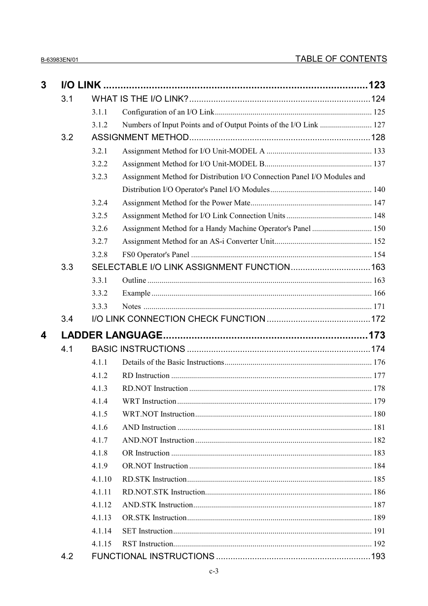
3 I/O LINK
3.1 WHAT IS THE I/O LINK?
3.1.1 Configuration of an I/O Link
3.1.2 Numbers of Input Points and of Output Points of the I/O Link
3.2 ASSIGNMENT METHOD
3.2.1 Assignment Method for I/O Unit-MODEL A
3.2.2 Assignment Method for I/O Unit-MODEL B
3.2.3 Assignment Method for Distribution I/O Connection Panel I/O Modules and Distribution I/O Operator's Panel I/O Modules
3.2.4 Assignment Method for the Power Mate
3.2.5 Assignment Method for I/O Link Connection Units
3.2.6 Assignment Method for a Handy Machine Operator's Panel
3.2.7 Assignment Method for an AS-i Converter Unit
3.2.8 FS0 Operator's Panel
3.3 SELECTABLE I/O LINK ASSIGNMENT FUNCTION
3.3.1 Outline
3.3.2 Example
3.3.3 Notes
3.4 I/O LINK CONNECTION CHECK FUNCTION
4 LADDER LANGUAGE
4.1 BASIC INSTRUCTIONS
4.1.1 Details of the Basic Instructions
4.1.2 RD Instruction
4.1.3 RD.NOT Instruction
4.1.4 WRT Instruction
4.1.5 WRT.NOT Instruction
4.1.6 AND Instruction
4.1.7 AND.NOT Instruction
4.1.8 OR Instruction
4.1.9 OR.NOT Instruction
4.1.10 RD.STK Instruction
4.1.11 RD.NOT.STK Instruction
4.1.12 AND.STK Instruction
4.1.13 OR.STK Instruction
4.1.14 SET Instruction
4.1.15 RST Instruction
4.2 FUNCTIONAL INSTRUCTIONS
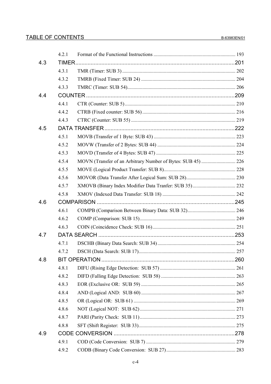
4.2.1 Format of the Functional Instructions
4.3 TIMER
4.3.1 TMR (Timer: SUB 3)
4.3.2 TMRB (Fixed Timer: SUB 24)
4.3.3 TMRC (Timer: SUB 54)
4.4 COUNTER
4.4.1 CTR (Counter: SUB 5)
4.4.2 CTRB (Fixed counter: SUB 56)
4.4.3 CTRC (Counter: SUB 55)
4.5 DATA TRANSFER
4.5.1 MOVB (Transfer of 1 Byte: SUB 43)
4.5.2 MOVW (Transfer of 2 Bytes: SUB 44)
4.5.3 MOVD (Transfer of 4 Bytes: SUB 47)
4.5.4 MOVN (Transfer of an Arbitrary Number of Bytes: SUB 45)
4.5.5 MOVE (Logical Product Transfer: SUB 8)
4.5.6 MOVOR (Data Transfer After Logical Sum: SUB 28)
4.5.7 XMOVB (Binary Index Modifier Data Tranfer: SUB 35)
4.5.8 XMOV (Indexed Data Transfer: SUB 18)
4.6 COMPARISON
4.6.1 COMPB (Comparison Between Binary Data: SUB 32)
4.6.2 COMP (Comparison: SUB 15)
4.6.3 COIN (Coincidence Check: SUB 16)
4.7 DATA SEARCH
4.7.1 DSCHB (Binary Data Search: SUB 34)
4.7.2 DSCH (Data Search: SUB 17)
4.8 BIT OPERATION
4.8.1 DIFU (Rising Edge Detection: SUB 57)
4.8.2 DIFD (Falling Edge Detection: SUB 58)
4.8.3 EOR (Exclusive OR: SUB 59)
4.8.4 AND (Logical AND: SUB 60)
4.8.5 OR (Logical OR: SUB 61)
4.8.6 NOT (Logical NOT: SUB 62)
4.8.7 PARI (Parity Check: SUB 11)
4.8.8 SFT (Shift Register: SUB 33)
4.9 CODE CONVERSION
4.9.1 COD (Code Conversion: SUB 7)
4.9.2 CODB (Binary Code Conversion: SUB 27)
4.9.3 DCNV (Data Conversion: SUB 14)
4.9.4 DCNVB (Extended Data Conversion: SUB 31)
4.9.5 DEC (Decode: SUB 4)
4.9.6 DECB (Binary Decoding: SUB 25)
4.10 OPERATION INSTRUCTION
4.10.1 ADDB (Binary Addition: SUB 36)
4.10.2 SUBB (Binary Subtraction: SUB 37)
4.10.3 MULB (Binary Multiplication: SUB 38)
4.10.4 DIVB (Binary Division: SUB 39)
4.10.5 ADD (BCD Addition: SUB 19)
4.10.6 SUB (BCD Subtraction: SUB 20)
4.10.7 MUL (BCD Multiplication: SUB 21)
4.10.8 DIV (BCD Division: SUB 22)
4.10.9 NUMEB (Definition of Binary Constants: SUB 40)
4.10.10 NUME (BCD Definition of Constant: SUB 23)
4.11 INSTRUCTIONS RELATED TO CNC FUNCTIONS
4.11.1 DISPB (Display Message: SUB 41)
4.11.2 EXIN (External Data Input: SUB 42)
4.11.3 WINDR (Reading CNC Window Data: SUB 51)
4.11.4 WINDW (Writing CNC Window Data: SUB 52)
4.11.5 AXCTL (Axis Control by PMC: SUB 53)
4.12 PROGRAM CONTROL
4.12.1 COM (Common Line Control: SUB 9)
4.12.2 COME (Common Line Control End: SUB 29)
4.12.3 JMP (Jump: SUB 10)
4.12.4 JMPE (Jump End: SUB 30)
4.12.5 JMPB (Label Jump 1: SUB 68)
4.12.6 JMPC (Label Jump 2: SUB 73)
4.12.7 LBL (Label: SUB 69)
4.12.8 CALL (Conditional Subprogram Call: SUB 65)
4.12.9 CALLU (Unconditional Subprogram Call: SUB 66)
4.12.10 SP (Subprogram: SUB 71)
4.12.11 SPE (End of a Subprogram: SUB 72)
4.12.12 END1 (1st Level Sequence Program End: SUB 1)
4.12.13 END2 (2nd Level Sequence Program End: SUB 2)
4.12.14 END3 (3rd Level Sequence Program End: SUB 48)
4.12.15 END (End of a Ladder Program: SUB 64)
4.12.16 NOP (No Operation: SUB 70)
4.13 ROTATION CONTROL
4.13.1 ROT (Rotation Control: SUB 6)
4.13.2 ROTB (Binary Rotation Control: SUB 26)
4.14 INVALID INSTRUCTIONS
4.15 NOTE ON PROGRAMMING
5 WINDOW FUNCTIONS
5.1 FORMATS OF CONTROL DATA
5.2 LOW-SPEED RESPONSE AND HIGH-SPEED RESPONSE
5.2.1 Note on the Programming of a Low-speed Response Window Instruction
5.3 LIST OF WINDOW FUNCTIONS
5.4 CNC INFORMATION
5.4.1 Reading CNC System Information (High-speed Response)
5.4.2 Reading a Tool Offset (High-speed Response)
5.4.3 Writing a Tool Offset (Low-speed Response)
5.4.4 Reading a Workpiece Origin Offset Value (High-speed Response)
5.4.5 Writing a Workpiece Origin Offset Value (Low-speed Response)
5.4.6 Reading a Parameter (High-speed Response)
5.4.7 Writing a Parameter (Low-speed Response)
5.4.8 Reading a Real Type Parameter (High-speed Response)
5.4.9 Writing a Real Type Parameter (Low-speed Response)
5.4.10 Reading Setting Data (High-speed Response)
5.4.11 Writing Setting Data (Low-speed Response)
5.4.12 Reading the Current Program Number (High-speed Response)
5.4.13 Reading the Current Sequence Number (High-speed Response)
5.4.14 Reading CNC Status Information (High-speed Response)
5.4.15 Reading the Current Program Number (8-digit Program Numbers) (High-speed Response)
5.4.16 Entering Data on the Program Check Screen (Low-speed Response)
5.4.17 Reading Clock Data (Date and Time) (High-speed Response)
5.5 AXIS INFORMATION
5.5.1 Reading the Actual Velocity of Controlled Axes (High-speed Response)
5.5.2 Reading the Absolute Position (Absolute Coordinates) of Controlled Axes (High-speed Response)
5.5.3 Reading the Machine Position (Machine Coordinates) of Controlled Axes (High-speed Response)
5.5.4 Reading a Skip Position (Stop Coordinates of Skip Operation (G31)) of Controlled Axes (High-speed Response)
5.5.5 Reading the Servo Delay for Controlled Axes (High-speed Response)
5.5.6 Reading the Acceleration/Deceleration Delay on Controlled Axes (High-speed Response)
5.5.7 Reading the Actual Spindle Speed (High-speed Response)
5.5.8 Reading the Relative Position on a Controlled Axis (High-speed Response)
5.5.9 Reading the Remaining Travel (High-speed Response)
5.5.10 Reading Actual Spindle Speeds (High-speed Response)
5.5.11 Entering Torque Limit Data for the Digital Servo Motor (Low-speed Response)
5.5.12 Presetting the Relative Coordinate (Low-speed Response)
6 OPERATING THE PMC SCREEN
6.1 OPERATION SCREENS OF THE PMC AND SOFT KEY ORGANIZATION
6.1.1 Transition of the PMC Screens
6.1.2 Basic Screen Operations
6.2 DISPLAY AND OPERATION CONDITIONS FOR SCREENS
6.2.1 Programmer Protection Function
6.2.2 PMC Parameter Input/Output Conditions
6.2.3 Password Function
6.3 MULTI-PMC DISPLAY
7 PMC DIAGNOSIS AND MAINTENANCE SCREENS ([PMC MAINTE])
7.1 MONITORING PMC SIGNAL STATUS ([STATUS] SCREEN)
7.1.1 Forced I/O Function
7.1.2 Forced I/O Screen
7.2 CHECKING PMC ALARMS ([PMC ALARM] SCREEN)
7.3 SETTING AND DISPLAYING PMC PARAMETERS
7.3.1 Setting and Displaying Variable Timers ([TIMER] Screen)
7.3.2 Setting and Displaying Counter Values ([COUNTR] Screen)
7.3.3 Setting and Displaying Keep Relays ([KEEP RELAY] Screen)
7.3.4 Setting and Displaying Data Tables ([DATA] Screen)
7.4 SEQUENCE PROGRAM AND PMC PARAMETER I/O ([I/O] SCREEN)
7.4.1 Writing to the Memory Card
7.4.2 Setting the Communication Port ([PORT SETING] Screen)
7.4.3 Displaying a File List ([LIST] Screen)
7.4.4 Setting an I/O Target PMC
7.4.5 Outputting a Sequence Program to the Memory Card
7.4.6 Inputting a Sequence Program from the Memory Card
7.4.7 Comparing Sequence Programs with Memory Card Files
7.4.8 Saving Sequence Programs to the Flash ROM
7.4.9 Inputting Sequence Programs from the Flash ROM
7.4.10 Comparing Sequence Programs with Flash ROM Files
7.4.11 Outputting a Sequence Program to the FLOPPY
7.4.12 Inputting a Sequence Program from the FLOPPY
7.4.13 Comparing Sequence Programs with FLOPPY Files
7.4.14 Outputting Sequence Programs to Other Devices (via the RS-232C Port)
7.4.15 Inputting Sequence Programs from Other Devices (via the RS-232C Port)
7.4.16 Comparing Sequence Programs with Files of Other Devices (via the RS-232C Port)
7.4.17 Outputting PMC Parameters to the Memory Card
7.4.18 Inputting PMC Parameters from the Memory Card
7.4.19 Comparing PMC Parameters with Memory Card Files
7.4.20 Outputting PMC Parameters to the FLOPPY
7.4.21 Inputting PMC Parameters from the FLOPPY
7.4.22 Comparing PMC Parameters with FLOPPY Files
7.4.23 Outputting PMC Parameters to Other Devices (via the RS-232C Port)
7.4.24 Inputting PMC Parameters from Other Devices (via the RS-232C Port)
7.4.25 Comparing PMC Parameters with Files of Other Devices (via the RS-232C Port)
7.4.26 Deleting Memory Card Files or Formatting a Memory Card
7.4.27 Deleting One or All FLOPPY Files
7.5 DISPLAYING I/O LINK CONNECTION STATUS ([I/O LINK] SCREEN)
7.6 TRACING AND DISPLAYING PMC SIGNAL STATUS
7.6.1 Signal Trace Function ([TRACE] Screen)
7.6.2 Setting of Trace Parameter ([TRACE SETING] Screen)
7.6.3 Execution of Trace
7.6.4 Operation after Execution of Trace
7.6.5 Automatic Start of Trace Setting
7.6.6 Trace Result Output
8 LADDER DIAGRAM MONITOR AND EDITOR SCREENS ([PMC LADDER])
8.1 DISPLAYING A PROGRAM LIST ([LIST] SCREEN)
8.1.1 Setting the Program List Screen
8.2 MONITORING LADDER DIAGRAMS ([LADDER] SCREEN)
8.2.1 Operating on the LADDER DIAGRAM MONITOR Screen
8.2.2 Setting the Display Format of the LADDER DIAGRAM MONITOR Screen
8.2.3 Display Format for Parameters
8.2.4 FUNCTIONAL INSTRUCTION DATA TABLE VIEWER Screen
8.3 EDITING LADDER PROGRAMS
8.3.1 Operating on the LADDER DIAGRAM EDITOR Screen
8.3.2 Setting the LADDER DIAGRAM EDITOR Screen
8.3.3 NET EDITOR Screen
8.3.4 Structure of Valid Net
8.3.5 FUNCTIONAL INSTRUCTION LIST Screen
8.3.6 FUNCTIONAL INSTRUCTION DATA TABLE EDITOR Screen
8.3.7 Operating on the FUNCTIONAL INSTRUCTION DATA TABLE EDITOR Screen
8.3.8 PROGRAM LIST EDITOR Screen
8.3.9 Setting the PROGRAM LIST EDITOR Screen
8.4 SELECTING AND DISPLAYING THE NECESSARY LADDER NET ([SWITCH] SCREEN])
8.4.1 Collective Monitor Function
8.4.2 COLLECTIVE MONITOR Function
8.5 ADDRESS ALTERATION FUNCTION
8.5.1 Screen Structures
8.5.2 Operating on the Screen
8.6 FUNCTION TO REFERENCE ADDRESSES IN USE
8.6.1 Address Map Display Screen
8.6.2 Operating on the Screen
8.7 FUNCTION TO AUTOMATICALLY INPUT UNSUSED ADDRESSES
8.8 AUTOMATICALLY INPUTTING UNUSED PARAMETER NUMBERS
8.9 DETECTION OF DOUBLE COILS
9 PMC CONFIGURATION DATA SETTING SCREENS ([PMC CONFIG])
9.1 DISPLAYING AND EDITING TITLE DATA ([TITLE] SCREENS)
9.1.1 Displaying Title Data
9.1.2 Editing Title Data
9.2 DISPLAYING AND EDITING SYMBOL AND COMMENT DATA ([SYMBOL] SCREENS)
9.2.1 Displaying Symbol and Comment Data
9.2.2 Editing Symbol and Comment Data
9.2.3 Partially Changing Symbol and Comment Data
9.2.4 Registering New Symbol and Comment Data
9.3 DISPLAYING AND EDITING MESSAGE DATA ([MESAGE] SCREENS)
9.3.1 Displaying Message Data
9.3.2 Editing Message Data
9.3.3 Editing Desired Message Data
9.4 DISPLAYING AND EDITING I/O MODULE ALLOCATION DATA ([MODULE] SCREENS)
9.4.1 Displaying I/O Module Allocation Data
9.4.2 Editing I/O Module Allocation Data
9.5 DISPLAYING AND EDITING PMC SETTINGS ([SETING] SCREENS)
9.6 DISPLAYING THE STATUS OF PMCS AND CHANGING THE TARGET PMC ([PMC STATUS] SCREENS)
9.6.1 Starting and Stopping Sequence Programs
9.7 DISPLAYING AND SETTING PARAMETERS FOR THE ONLINE FUNCTION ([ONLINE] SCREEN)
9.7.1 Setting Parameters for the Online Function
9.7.2 Communication Status
9.7.3 About Ethernet Communication Parameters
9.7.4 About connection log of Ethernet
9.8 DISPLAYING AND SETTING SYSTEM PARAMETERS ([SYSTEM PARAM] SCREENS)
9.8.1 Displaying and Setting the Counter Data Type
9.8.2 Displaying and Setting Parameters for an FS0 Operator's Panel
9.8.3 Displaying and Setting Parameters for the Selectable I/O Link Assignment Function
9.9 DISPLAYING AND SETTING CONFIGURATION PARAMETERS ([CONFIG PARAM] SCREENS)
9.9.1 Menu for Setting Configuration Parameters
9.9.2 Setting the CNC-PMC Interface
9.9.3 Setting the Machine Signal Interface
9.9.4 Setting the Parameters Related to Ladder Execution
10 PMC ALARM MESSAGES AND ACTIONS TO TAKE
10.1 ALARM MESSAGE LIST
10.1.1 Messages That May Be Displayed on the PMC Alarm Screen
10.1.2 PMC System Alarm Messages
10.1.3 Operation Errors
10.1.4 I/O Communication Error Messages
10.2 I/O LINK COMMUNICATION ERRORS AND ACTIONS TO TAKE
10.2.1 Causes of Communication Errors
10.2.2 Check Items
10.2.3 Sample Cases
INDEX
Revision Record
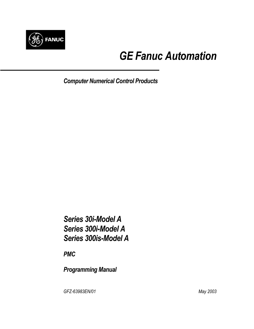
GE Fanuc Automation Computer Numerical Control Products Series 30i-Model A Series 300i-Model A Series 300is-Model A PMC Programming Manual GFZ-63983EN/01 May 2003
Warnings, Cautions, and Notes as Used in this Publication GFL-001 Warning Warning notices are used in this publication to emphasize that hazardous voltages, currents, temperatures, or other conditions that could cause personal injury exist in this equipment or may be associated with its use. In situations where inattention could cause either personal injury or damage to equipment, a Warning notice is used. Caution notices are used where equipment might be damaged if care is not taken. Caution Notes merely call attention to information that is especially significant to understanding and operating the equipment. Note This document is based on information available at the time of its publication. While efforts have been made to be accurate, the information contained herein does not purport to cover all details or variations in hardware or software, nor to provide for every possible contingency in connection with installation, operation, or maintenance. Features may be described herein which are not present in all hardware and software systems. GE Fanuc Automation assumes no obligation of notice to holders of this document with respect to changes subsequently made. GE Fanuc Automation makes no representation or warranty, expressed, implied, or statutory with respect to, and assumes no responsibility for the accuracy, completeness, sufficiency, or usefulness of the information contained herein. No warranties of merchantability or fitness for purpose shall apply. ©Copyright 2003 GE Fanuc Automation North America, Inc. All Rights Reserved.
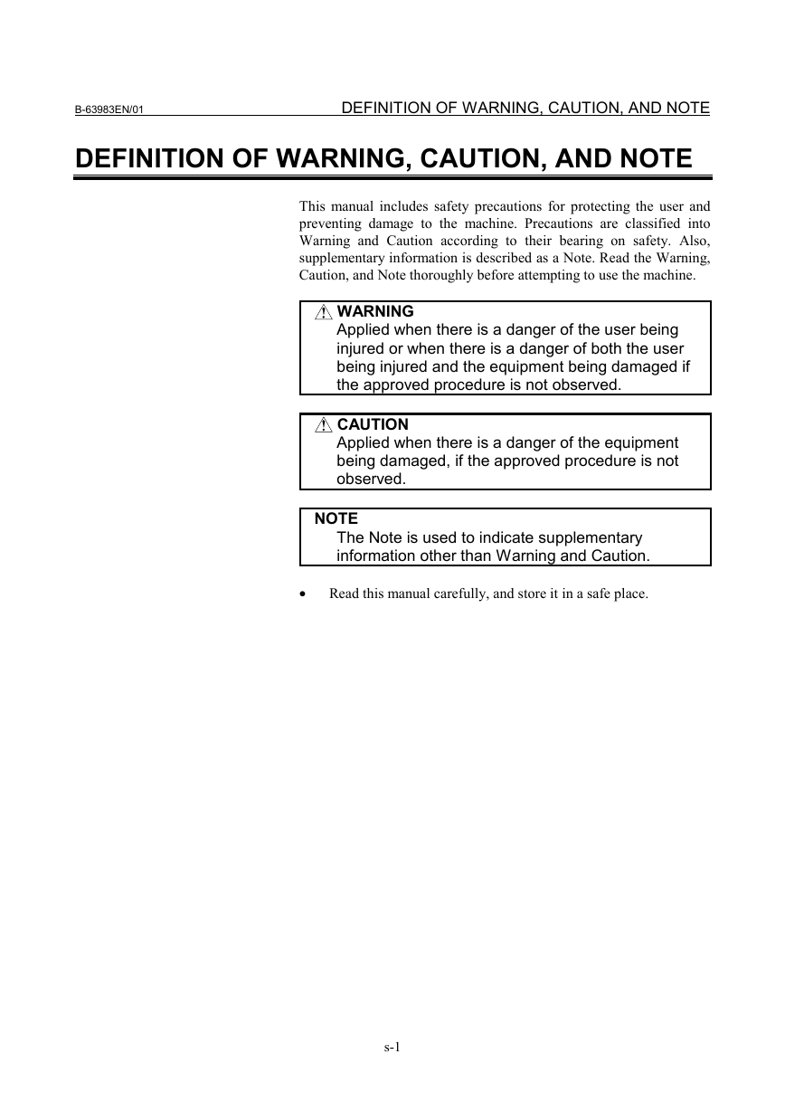
B-63983EN/01 DEFINITION OF WARNING, CAUTION, AND NOTE DEFINITION OF WARNING, CAUTION, AND NOTE This manual includes safety precautions for protecting the user and preventing damage to the machine. Precautions are classified into Warning and Caution according to their bearing on safety. Also, supplementary information is described as a Note. Read the Warning, Caution, and Note thoroughly before attempting to use the machine. WARNING Applied when there is a danger of the user being injured or when there is a danger of both the user being injured and the equipment being damaged if the approved procedure is not observed. CAUTION Applied when there is a danger of the equipment being damaged, if the approved procedure is not observed. NOTE The Note is used to indicate supplementary information other than Warning and Caution. • Read this manual carefully, and store it in a safe place. s-1
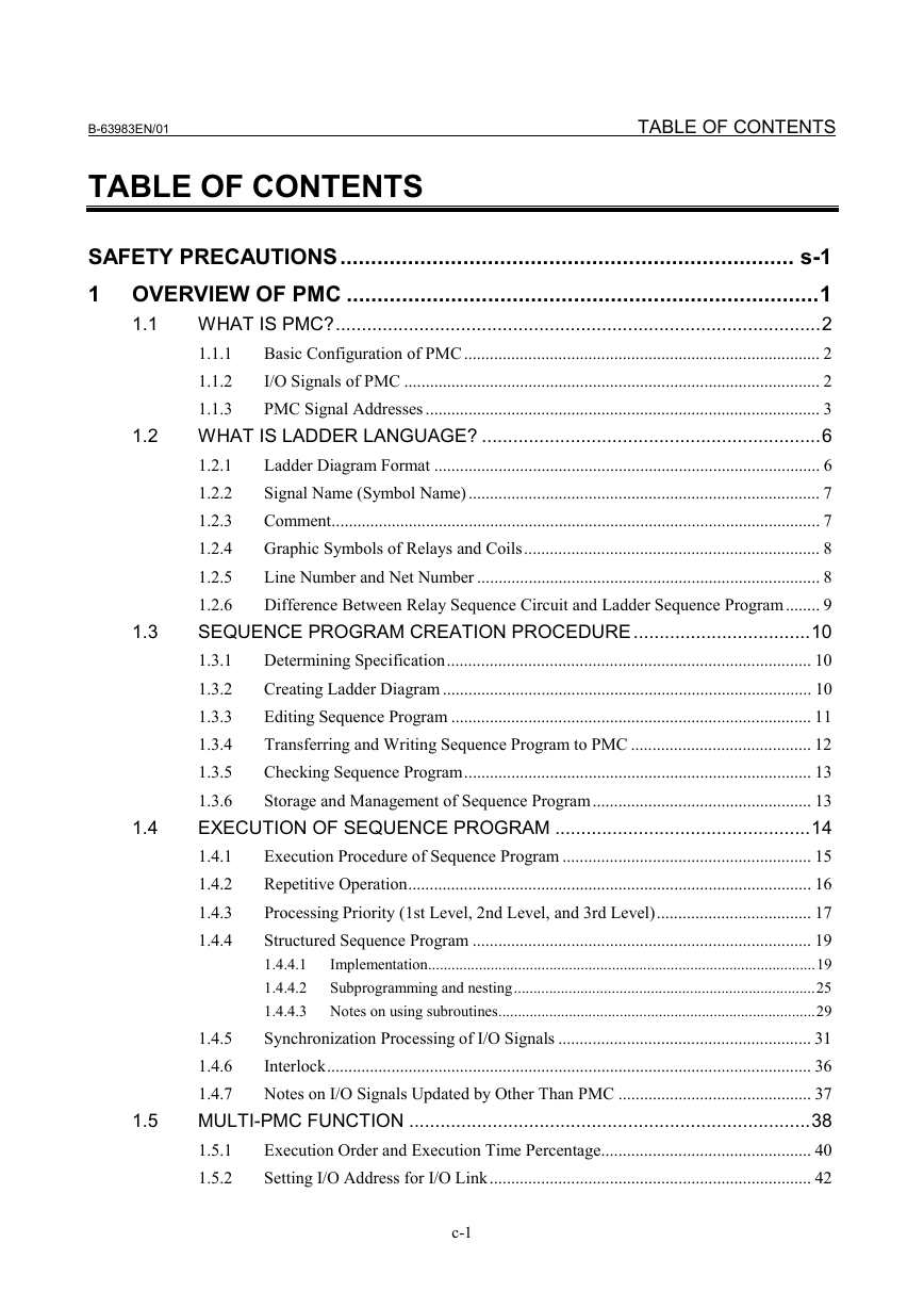
B-63983EN/01 TABLE OF CONTENTS TABLE OF CONTENTS 1.2 1.1 SAFETY PRECAUTIONS.......................................................................... s-1 1 OVERVIEW OF PMC .............................................................................1 WHAT IS PMC?.............................................................................................2 1.1.1 Basic Configuration of PMC................................................................................... 2 I/O Signals of PMC ................................................................................................. 2 1.1.2 1.1.3 PMC Signal Addresses ............................................................................................ 3 WHAT IS LADDER LANGUAGE? .................................................................6 Ladder Diagram Format .......................................................................................... 6 1.2.1 Signal Name (Symbol Name).................................................................................. 7 1.2.2 1.2.3 Comment.................................................................................................................. 7 Graphic Symbols of Relays and Coils..................................................................... 8 1.2.4 1.2.5 Line Number and Net Number ................................................................................ 8 1.2.6 Difference Between Relay Sequence Circuit and Ladder Sequence Program........ 9 SEQUENCE PROGRAM CREATION PROCEDURE..................................10 1.3.1 Determining Specification..................................................................................... 10 Creating Ladder Diagram ...................................................................................... 10 1.3.2 Editing Sequence Program .................................................................................... 11 1.3.3 1.3.4 Transferring and Writing Sequence Program to PMC .......................................... 12 Checking Sequence Program................................................................................. 13 1.3.5 1.3.6 Storage and Management of Sequence Program................................................... 13 EXECUTION OF SEQUENCE PROGRAM .................................................14 Execution Procedure of Sequence Program .......................................................... 15 1.4.1 1.4.2 Repetitive Operation.............................................................................................. 16 Processing Priority (1st Level, 2nd Level, and 3rd Level).................................... 17 1.4.3 Structured Sequence Program ............................................................................... 19 1.4.4 Implementation...................................................................................................19 1.4.4.1 1.4.4.2 Subprogramming and nesting.............................................................................25 1.4.4.3 Notes on using subroutines.................................................................................29 Synchronization Processing of I/O Signals ........................................................... 31 1.4.5 Interlock................................................................................................................. 36 1.4.6 1.4.7 Notes on I/O Signals Updated by Other Than PMC ............................................. 37 MULTI-PMC FUNCTION .............................................................................38 Execution Order and Execution Time Percentage................................................. 40 1.5.1 1.5.2 Setting I/O Address for I/O Link........................................................................... 42 1.3 1.4 1.5 c-1
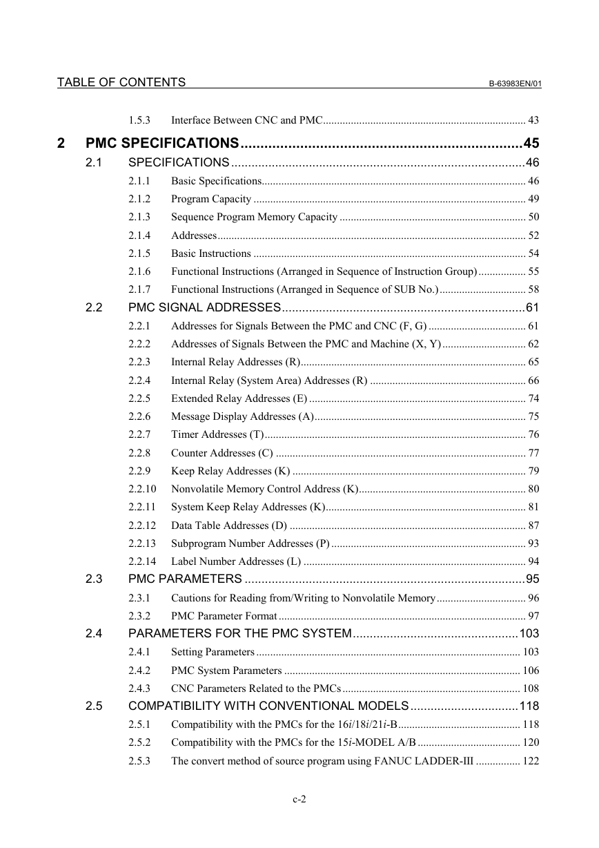
TABLE OF CONTENTS B-63983EN/01 2 2.2 1.5.3 Interface Between CNC and PMC......................................................................... 43 PMC SPECIFICATIONS.......................................................................45 SPECIFICATIONS.......................................................................................46 2.1 2.1.1 Basic Specifications............................................................................................... 46 Program Capacity .................................................................................................. 49 2.1.2 Sequence Program Memory Capacity ................................................................... 50 2.1.3 2.1.4 Addresses............................................................................................................... 52 Basic Instructions .................................................................................................. 54 2.1.5 2.1.6 Functional Instructions (Arranged in Sequence of Instruction Group)................. 55 2.1.7 Functional Instructions (Arranged in Sequence of SUB No.)............................... 58 PMC SIGNAL ADDRESSES........................................................................61 2.2.1 Addresses for Signals Between the PMC and CNC (F, G) ................................... 61 Addresses of Signals Between the PMC and Machine (X, Y).............................. 62 2.2.2 Internal Relay Addresses (R)................................................................................. 65 2.2.3 2.2.4 Internal Relay (System Area) Addresses (R) ........................................................ 66 Extended Relay Addresses (E) .............................................................................. 74 2.2.5 Message Display Addresses (A)............................................................................ 75 2.2.6 2.2.7 Timer Addresses (T).............................................................................................. 76 Counter Addresses (C) .......................................................................................... 77 2.2.8 2.2.9 Keep Relay Addresses (K) .................................................................................... 79 2.2.10 Nonvolatile Memory Control Address (K)............................................................ 80 2.2.11 System Keep Relay Addresses (K)........................................................................ 81 2.2.12 Data Table Addresses (D) ..................................................................................... 87 Subprogram Number Addresses (P) ...................................................................... 93 2.2.13 2.2.14 Label Number Addresses (L) ................................................................................ 94 PMC PARAMETERS ...................................................................................95 Cautions for Reading from/Writing to Nonvolatile Memory................................ 96 2.3.1 2.3.2 PMC Parameter Format ......................................................................................... 97 PARAMETERS FOR THE PMC SYSTEM.................................................103 Setting Parameters ............................................................................................... 103 2.4.1 2.4.2 PMC System Parameters ..................................................................................... 106 2.4.3 CNC Parameters Related to the PMCs................................................................ 108 COMPATIBILITY WITH CONVENTIONAL MODELS................................118 2.5.1 Compatibility with the PMCs for the 16i/18i/21i-B............................................ 118 Compatibility with the PMCs for the 15i-MODEL A/B ..................................... 120 2.5.2 2.5.3 The convert method of source program using FANUC LADDER-III ................ 122 2.3 2.4 2.5 c-2
B-63983EN/01 TABLE OF CONTENTS 3 4 3.2 I/O LINK .............................................................................................123 WHAT IS THE I/O LINK?...........................................................................124 3.1 Configuration of an I/O Link............................................................................... 125 3.1.1 3.1.2 Numbers of Input Points and of Output Points of the I/O Link .......................... 127 ASSIGNMENT METHOD...........................................................................128 Assignment Method for I/O Unit-MODEL A ..................................................... 133 3.2.1 3.2.2 Assignment Method for I/O Unit-MODEL B...................................................... 137 Assignment Method for Distribution I/O Connection Panel I/O Modules and 3.2.3 Distribution I/O Operator's Panel I/O Modules................................................... 140 Assignment Method for the Power Mate............................................................. 147 3.2.4 Assignment Method for I/O Link Connection Units ........................................... 148 3.2.5 Assignment Method for a Handy Machine Operator's Panel .............................. 150 3.2.6 Assignment Method for an AS-i Converter Unit................................................. 152 3.2.7 3.2.8 FS0 Operator's Panel ........................................................................................... 154 SELECTABLE I/O LINK ASSIGNMENT FUNCTION.................................163 Outline ................................................................................................................. 163 3.3.1 Example ............................................................................................................... 166 3.3.2 3.3.3 Notes ................................................................................................................... 171 3.4 I/O LINK CONNECTION CHECK FUNCTION ...........................................172 LADDER LANGUAGE........................................................................173 4.1 BASIC INSTRUCTIONS ............................................................................174 Details of the Basic Instructions.......................................................................... 176 4.1.1 4.1.2 RD Instruction ..................................................................................................... 177 4.1.3 RD.NOT Instruction ............................................................................................ 178 4.1.4 WRT Instruction.................................................................................................. 179 4.1.5 WRT.NOT Instruction......................................................................................... 180 AND Instruction .................................................................................................. 181 4.1.6 AND.NOT Instruction......................................................................................... 182 4.1.7 4.1.8 OR Instruction ..................................................................................................... 183 OR.NOT Instruction ............................................................................................ 184 4.1.9 4.1.10 RD.STK Instruction............................................................................................. 185 4.1.11 RD.NOT.STK Instruction.................................................................................... 186 4.1.12 AND.STK Instruction.......................................................................................... 187 4.1.13 OR.STK Instruction............................................................................................. 189 SET Instruction.................................................................................................... 191 4.1.14 4.1.15 RST Instruction.................................................................................................... 192 FUNCTIONAL INSTRUCTIONS ................................................................193 3.3 4.2 c-3
TABLE OF CONTENTS B-63983EN/01 4.3 4.4 4.5 4.6 4.7 4.8 4.9 Format of the Functional Instructions ................................................................. 193 4.2.1 TIMER........................................................................................................201 TMR (Timer: SUB 3) .......................................................................................... 202 4.3.1 4.3.2 TMRB (Fixed Timer: SUB 24) ........................................................................... 204 4.3.3 TMRC (Timer: SUB 54)...................................................................................... 206 COUNTER .................................................................................................209 4.4.1 CTR (Counter: SUB 5)........................................................................................ 210 CTRB (Fixed counter: SUB 56) .......................................................................... 216 4.4.2 4.4.3 CTRC (Counter: SUB 55) ................................................................................... 219 DATA TRANSFER.....................................................................................222 MOVB (Transfer of 1 Byte: SUB 43) ................................................................. 223 4.5.1 MOVW (Transfer of 2 Bytes: SUB 44) .............................................................. 224 4.5.2 4.5.3 MOVD (Transfer of 4 Bytes: SUB 47) ............................................................... 225 MOVN (Transfer of an Arbitrary Number of Bytes: SUB 45) ........................... 226 4.5.4 4.5.5 MOVE (Logical Product Transfer: SUB 8)......................................................... 228 MOVOR (Data Transfer After Logical Sum: SUB 28)....................................... 230 4.5.6 XMOVB (Binary Index Modifier Data Tranfer: SUB 35).................................. 232 4.5.7 4.5.8 XMOV (Indexed Data Transfer: SUB 18) .......................................................... 242 COMPARISON ..........................................................................................245 COMPB (Comparison Between Binary Data: SUB 32)...................................... 246 4.6.1 4.6.2 COMP (Comparison: SUB 15)............................................................................ 249 4.6.3 COIN (Coincidence Check: SUB 16).................................................................. 251 DATA SEARCH .........................................................................................253 4.7.1 DSCHB (Binary Data Search: SUB 34) .............................................................. 254 4.7.2 DSCH (Data Search: SUB 17)............................................................................. 257 BIT OPERATION .......................................................................................260 DIFU (Rising Edge Detection: SUB 57) ............................................................ 261 4.8.1 DIFD (Falling Edge Detection: SUB 58) ........................................................... 263 4.8.2 4.8.3 EOR (Exclusive OR: SUB 59) ........................................................................... 265 AND (Logical AND: SUB 60) ........................................................................... 267 4.8.4 OR (Logical OR: SUB 61) ................................................................................. 269 4.8.5 4.8.6 NOT (Logical NOT: SUB 62)............................................................................ 271 PARI (Parity Check: SUB 11)............................................................................ 273 4.8.7 4.8.8 SFT (Shift Register: SUB 33)............................................................................. 275 CODE CONVERSION ...............................................................................278 COD (Code Conversion: SUB 7) ....................................................................... 279 4.9.1 4.9.2 CODB (Binary Code Conversion: SUB 27)....................................................... 283 c-4
分享到:
收藏