CMOS Analog Circuit Design (2nd Ed.) Homework Solutions : 9/20/2002
1
Chapter 1 Homework Solutions
1.1-1 Using Eq. (1) of Sec 1.1, give the base-10 value for the 5-bit binary number 11010
(b4 b3 b2 b1 b0 ordering).
From Eq. (1) of Sec 1.1 we have
bN-1 2-1 + b N-2 2-2 + bN-3 2-3 + ...+ b0 2-N =∑
bN-i2-i
N
i=1
0
1
1
1 × 2-1 + 1× 2-2 + 0 × 2-3 + 1 × 2-4 + 0 × 2-5 =
4 +
2 +
8 +
1
16 +
0
32
=
16 + 8 + 0 + 2 + 0
32
=
26
32 =
13
16
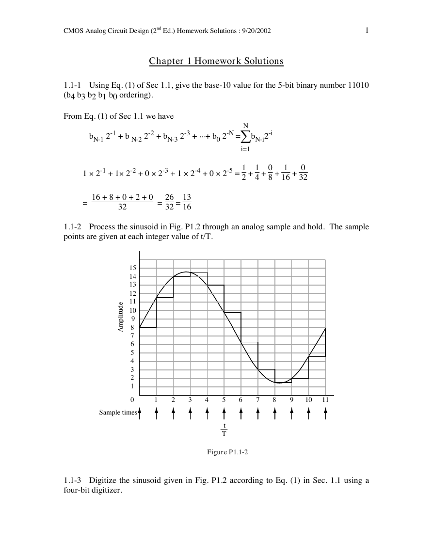
1.1-2 Process the sinusoid in Fig. P1.2 through an analog sample and hold. The sample
points are given at each integer value of t/T.
15
14
13
12
11
e
d
10
u
t
i
9
l
p
m
8A
7
6
5
4
3
2
1
0
1
2
3
4
5
6
7
8
9
10
11
Sample times
t
__
T
Figure P1.1-2
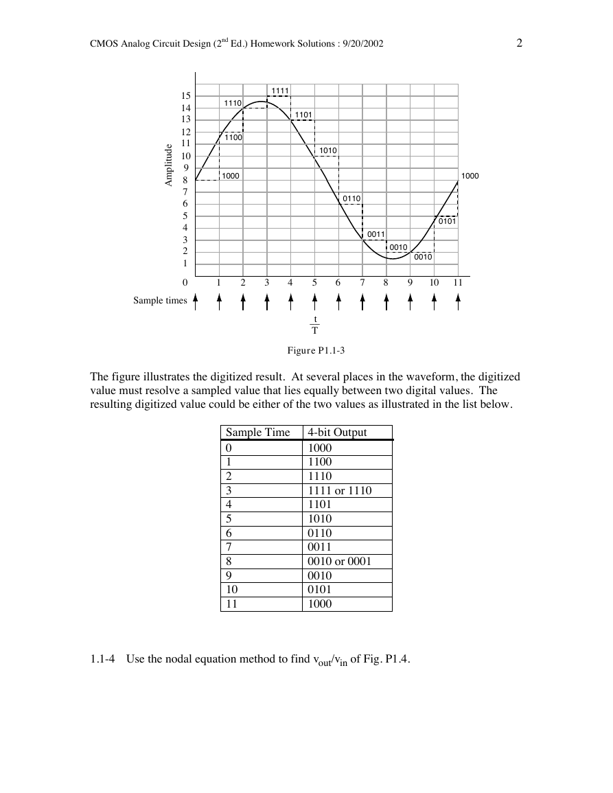
1.1-3 Digitize the sinusoid given in Fig. P1.2 according to Eq. (1) in Sec. 1.1 using a
four-bit digitizer.
�
CMOS Analog Circuit Design (2nd Ed.) Homework Solutions : 9/20/2002
2
1111
1101
1110
1100
1000
1010
0110
15
14
13
12
11
e
d
10
u
t
i
9
l
p
m
8A
7
6
5
4
3
2
1
1000
0101
0011
0010
0010
0
1
2
3
4
5
6
7
8
9
10
11
Sample times
t
__
T
Figure P1.1-3
The figure illustrates the digitized result. At several places in the waveform, the digitized
value must resolve a sampled value that lies equally between two digital values. The
resulting digitized value could be either of the two values as illustrated in the list below.
Sample Time
0
1
2
3
4
5
6
7
8
9
10
11
4-bit Output
1000
1100
1110
1111 or 1110
1101
1010
0110
0011
0010 or 0001
0010
0101
1000
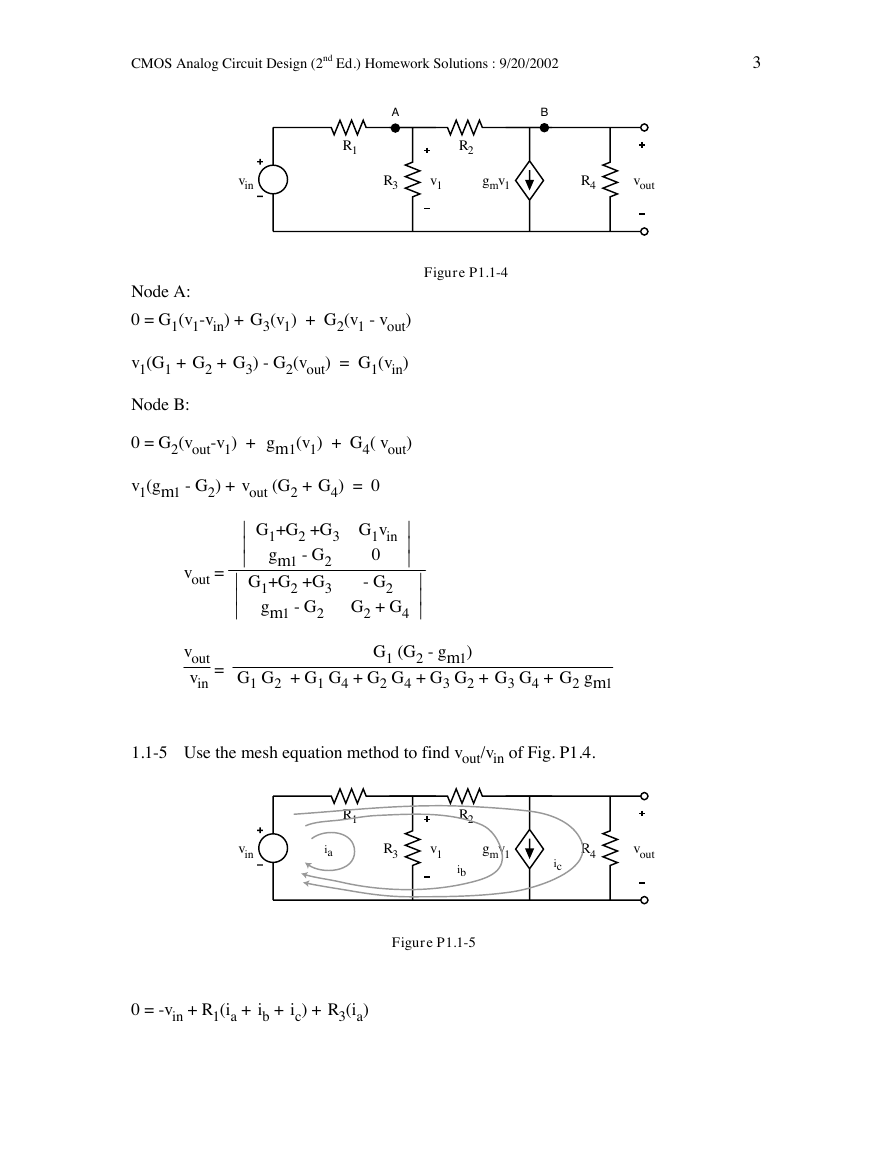
1.1-4 Use the nodal equation method to find vout/vin of Fig. P1.4.
�
CMOS Analog Circuit Design (2nd Ed.) Homework Solutions : 9/20/2002
3
A
B
R1
R2
vin
R3
v1
gmv1
R4
vout
Figure P1.1-4
Node A:
0 = G1(v1-vin) + G3(v1) + G2(v1 - vout)
v1(G1 + G2 + G3) - G2(vout) = G1(vin)
Node B:
0 = G2(vout-v1) + gm1(v1) + G4( vout)
v1(gm1 - G2) + vout (G2 + G4) = 0
G1+G2 +G3
gm1 - G2
G1+G2 +G3
gm1 - G2
G1vin
0
- G2
G2 + G4
vout =
vout
vin
=
G1 (G2 - gm1)
G1 G2 + G1 G4 + G2 G4 + G3 G2 + G3 G4 + G2 gm1
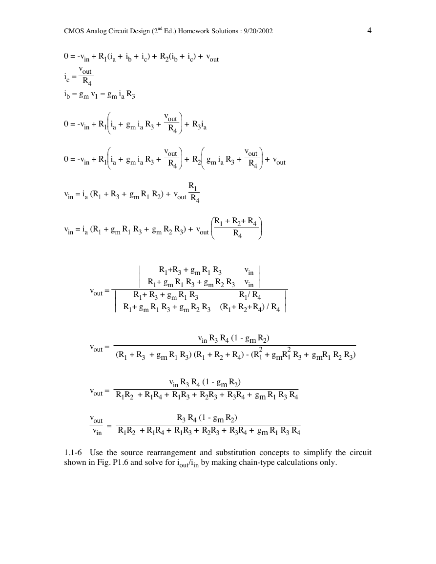
1.1-5 Use the mesh equation method to find vout/vin of Fig. P1.4.
R1
R2
vin
ia
R3
v1
gmv1
ib
R4
vout
ic
Figure P1.1-5
0 = -vin + R1(ia + ib + ic) + R3(ia)
�
CMOS Analog Circuit Design (2nd Ed.) Homework Solutions : 9/20/2002
4
0 = -vin + R1(ia + ib + ic) + R2(ib + ic) + vout
vout
R4
ic =
ib = gm v1 = gm ia R3
0 = -vin + R1
ia + gm ia R3 +
vout
R4
+ R3ia
0 = -vin + R1
ia + gm ia R3 +
vout
R4
gm ia R3 +
+ R2
vout
R4
+ vout
vin = ia (R1 + R3 + gm R1 R2) + vout
R1
R4
vin = ia (R1 + gm R1 R3 + gm R2 R3) + vout
R1 + R2+ R4
R4
R1+R3 + gm R1 R3
R1+ R3 + gm R1 R3
R1+ gm R1 R3 + gm R2 R3
vin
vin
R1/ R4
R1+ gm R1 R3 + gm R2 R3
(R1+ R2+R4) / R4
vin R3 R4 (1 - gm R2)
2
2
(R1 + R3 + gm R1 R3) (R1 + R2 + R4) - (R
1 + gmR
1 R3 + gmR1 R2 R3)
vout =
vout =
vout =
vout
vin
=
vin R3 R4 (1 - gm R2)
R1R2 + R1R4 + R1R3 + R2R3 + R3R4 + gm R1 R3 R4
R3 R4 (1 - gm R2)
R1R2 + R1R4 + R1R3 + R2R3 + R3R4 + gm R1 R3 R4
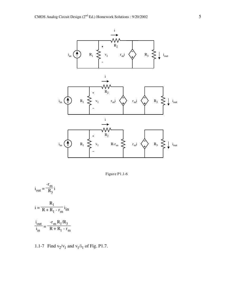
1.1-6 Use the source rearrangement and substitution concepts to simplify the circuit
shown in Fig. P1.6 and solve for iout/iin by making chain-type calculations only.
�
CMOS Analog Circuit Design (2nd Ed.) Homework Solutions : 9/20/2002
5
i
R2
iin
R1
v1
rmi
R3
iout
i
R2
iin
R1
v1
rmi
rmi
R3
iout
i
R2
iin
R1
v1
R-rm
rmi
R3
iout
Figure P1.1-6
iout =
-rm
R3
i
R1
i =
R + R1 - rm
iin
iout
iin =
-rm R1/R3
R + R1 - rm
1.1-7 Find v2/v1 and v1/i1 of Fig. P1.7.
�
CMOS Analog Circuit Design (2nd Ed.) Homework Solutions : 9/20/2002
6
gm(v1-v2)
i1
v1
RL
v2
Figure P1.1-7
v2
v1 = gm (v1 - v2) RL
v2 (1 + gm RL ) = gm RL v1
v2
v1 =
gm RL
1 + gm RL
v2 = i1 RL
substituting for v2 yields:
i1 RL
v1
=
gm RL
1 + gm RL
v1
i1
v1
i1
=
RL( 1 + gm RL )
gm RL
= RL +
1
gm
1.1-8 Use the circuit-reduction technique to solve for vout/vin of Fig. P1.8.
�
CMOS Analog Circuit Design (2nd Ed.) Homework Solutions : 9/20/2002
7
Av(vin - v1)
vin
R1
v1
R2
vout
N1
N2
Avv1
Avvin
vin
R1
v1
R2
vout
Multiply R1 by (Av + 1)
Figure P1.1-8a
Avvin
vin
v1
R1(Av+1)
R2
vout
Figure P1.1-8b
-Avvin R2
vout =
R2 + R1(Av+1)
vout
vin
=
-Av R2
R2 + R1(Av+1)
�
CMOS Analog Circuit Design (2nd Ed.) Homework Solutions : 9/20/2002
8
vout
vin
=
-Av
-Av + 1 R2
R2
Av + 1 + R1
As Av approaches infinity,
vout
vin
=
-R2
R1
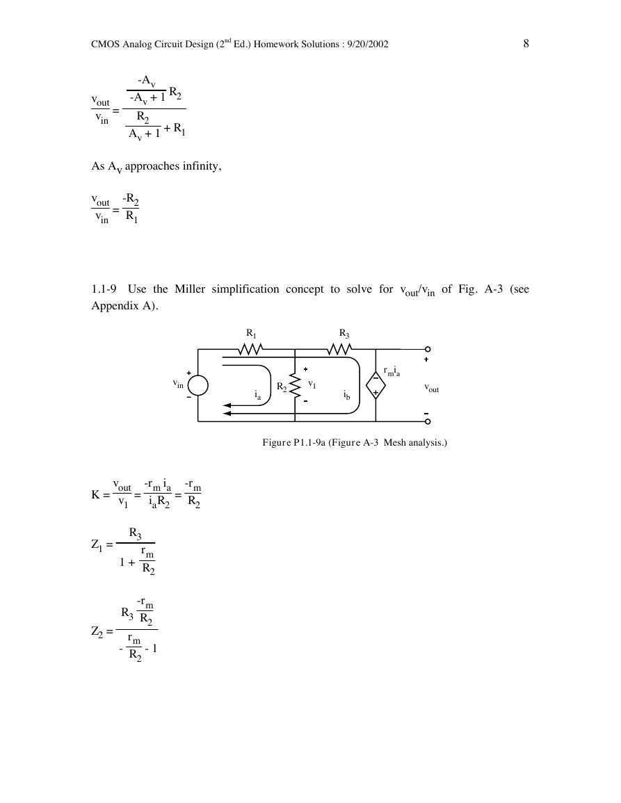
1.1-9 Use the Miller simplification concept to solve for vout/vin of Fig. A-3 (see
Appendix A).
R1
vin
R2
v1
ia
R3
ib
rmia
vout
Figure P1.1-9a (Figure A-3 Mesh analysis.)
=
-rm
R2
K =
=
vout
v1
-rm ia
iaR2
Z1 =
1 +
R3
rm
R2
Z2 =
-rm
R2
- 1
R3
rm
R2
-
�




 2023年江西萍乡中考道德与法治真题及答案.doc
 2012年重庆南川中考生物真题及答案.doc
 2013年江西师范大学地理学综合及文艺理论基础考研真题.doc
 2020年四川甘孜小升初语文真题及答案I卷.doc
 2020年注册岩土工程师专业基础考试真题及答案.doc
 2023-2024学年福建省厦门市九年级上学期数学月考试题及答案.doc
 2021-2022学年辽宁省沈阳市大东区九年级上学期语文期末试题及答案.doc
 2022-2023学年北京东城区初三第一学期物理期末试卷及答案.doc
 2018上半年江西教师资格初中地理学科知识与教学能力真题及答案.doc
 2012年河北国家公务员申论考试真题及答案-省级.doc
 2020-2021学年江苏省扬州市江都区邵樊片九年级上学期数学第一次质量检测试题及答案.doc
 2022下半年黑龙江教师资格证中学综合素质真题及答案.doc