Basics and low-cost solution proposals to move from legacy
USB2.0 connector to USB Type-C™ connector with STM32 devices
AN4775
Application note
Introduction
The USB Type-C™ and the Power Delivery is certainly one of the most promising
technology to simplify our daily life and to enhance our consumer and mobile user
experience.
This new reversible USB Type-C™ connector makes the plug insertion more user friendly.
The technology offers a single platform connector to carry all necessary data (including
video), and using Power Delivery protocol allows to negotiate up to 100W of power to supply
or charge equipment connecting to this USB port. Less cables, less connectors and
universal chargers are the final objective.
Natively the USB Type-C™ connector supports up to 15W (5V @ 3A) of power, extended to
100W (up to 20V @ 5A) with the optional USB Power Delivery feature.
15W of power is far enough for most of hundred of million of legacy USB powered devices
actually on the market.
This application note is a guideline to introduce this USB Type-CTM connector onto platform
to replace legacy USB2.0 connectors. It introduces some basis of the two new standards
USB Type-C™ and the USB Power Delivery.
This document proposes some schematics to replace in a simple way legacy USB2.0
connector by USB Type-C™ one on platform using USB2.0 communication.
Table 1 provides the list of products to which this application note applies.
Type
Table 1. Applicable products
Series
Microcontrollers
STM32L0 Series
STM32L1 Series
STM32L1W Series
STM32L4 Series
STM32F0 Series
STM32F1 Series
STM32F2 Series
STM32F3 Series
STM32F4 Series
STM32F7 Series
March 2016
DocID028454 Rev 1
1/23
www.st.com
1
�
AN4775
USB Type-C™ in a nutshell . . . . . . . . . . . . . . . . . . . . . . . . . . . . . . . . . . . 5
USB Type-C™ vocabulary . . . . . . . . . . . . . . . . . . . . . . . . . . . . . . . . . . . . . . . . . . . . . . . . . . . . 6
1.1
1.2
1.1.1
Minimum mandatory feature set . . . . . . . . . . . . . . . . . . . . . . . . . . . . . . . 6
Connector pin mapping . . . . . . . . . . . . . . . . . . . . . . . . . . . . . . . . . . . . . . . 7
1.2.1
VBUS power options . . . . . . . . . . . . . . . . . . . . . . . . . . . . . . . . . . . . . . . . . 8
CC Pins . . . . . . . . . . . . . . . . . . . . . . . . . . . . . . . . . . . . . . . . . . . . . . . . . . . 10
2.1
Plug orientation/cable twist detection . . . . . . . . . . . . . . . . . . . . . . . . . . . . 10
Power Capability detection and usage . . . . . . . . . . . . . . . . . . . . . . . . . . . .11
2.2
USB power delivery 2.0 . . . . . . . . . . . . . . . . . . . . . . . . . . . . . . . . . . . . . . 12
Power delivery signaling . . . . . . . . . . . . . . . . . . . . . . . . . . . . . . . . . . . . . . 12
3.1
Packet Structure . . . . . . . . . . . . . . . . . . . . . . . . . . . . . . . . . . . . . . . . . . 12
3.1.1
3.1.2
K-codes . . . . . . . . . . . . . . . . . . . . . . . . . . . . . . . . . . . . . . . . . . . . . . . . . 13
Negotiating Power . . . . . . . . . . . . . . . . . . . . . . . . . . . . . . . . . . . . . . . . . . 13
3.2
Alternate modes . . . . . . . . . . . . . . . . . . . . . . . . . . . . . . . . . . . . . . . . . . . 14
Alternate pins re-assignment . . . . . . . . . . . . . . . . . . . . . . . . . . . . . . . . . . 14
4.1
4.2
Billboard . . . . . . . . . . . . . . . . . . . . . . . . . . . . . . . . . . . . . . . . . . . . . . . . . . 15
Converting STM32xx USB2.0 device only to USB Type-C™ platform 16
Converting STM32xx USB2.0 host to USB Type-C™ platform . . . . . . 17
Converting legacy STM32xx USB2.0 OTG to USB Type-C™ platform 18
Conclusion . . . . . . . . . . . . . . . . . . . . . . . . . . . . . . . . . . . . . . . . . . . . . . . . 20
References . . . . . . . . . . . . . . . . . . . . . . . . . . . . . . . . . . . . . . . . . . . . . . . . 21
1
2
3
4
5
6
7
8
9
10
Revision history . . . . . . . . . . . . . . . . . . . . . . . . . . . . . . . . . . . . . . . . . . . 22
2/23
DocID028454 Rev 1
�
AN4775
Figure 1.
Figure 2.
Figure 3.
Figure 4.
Figure 5.
Figure 6.
Figure 7.
Figure 8.
Figure 9.
USB plug form factors. . . . . . . . . . . . . . . . . . . . . . . . . . . . . . . . . . . . . . . . . . . . . . . . . . . . . . 5
USB Type-C™ receptacle pinout. . . . . . . . . . . . . . . . . . . . . . . . . . . . . . . . . . . . . . . . . . . . . 7
Pull up/down CC detection . . . . . . . . . . . . . . . . . . . . . . . . . . . . . . . . . . . . . . . . . . . . . . . . . 10
SOP* signaling . . . . . . . . . . . . . . . . . . . . . . . . . . . . . . . . . . . . . . . . . . . . . . . . . . . . . . . . . . 12
Pins available for reconfiguration over the Full Featured Cable . . . . . . . . . . . . . . . . . . . . . 14
Pins available for reconfiguration for direct connect applications . . . . . . . . . . . . . . . . . . . . 15
Legacy device using USB Type-C™ receptacle . . . . . . . . . . . . . . . . . . . . . . . . . . . . . . . . 16
Legacy host using USB Type-C™ receptacle . . . . . . . . . . . . . . . . . . . . . . . . . . . . . . . . . . 17
Legacy OTG using USB Type-C™ receptacle . . . . . . . . . . . . . . . . . . . . . . . . . . . . . . . . . 18
DocID028454 Rev 1
3/23
3
�
Table 1.
Table 1.
Table 2.
Table 3.
Table 4.
Table 5.
Table 6.
Applicable products . . . . . . . . . . . . . . . . . . . . . . . . . . . . . . . . . . . . . . . . . . . . . . . . . . . . . . . 1
USB Type-C™ receptacle pinout meaning. . . . . . . . . . . . . . . . . . . . . . . . . . . . . . . . . . . . . . 8
Power supply options . . . . . . . . . . . . . . . . . . . . . . . . . . . . . . . . . . . . . . . . . . . . . . . . . . . . . . 9
DFP CC termination (Rp) requirements . . . . . . . . . . . . . . . . . . . . . . . . . . . . . . . . . . . . . . . 11
UFP CC Termination (Rd) Requirements . . . . . . . . . . . . . . . . . . . . . . . . . . . . . . . . . . . . . . 11
Voltage on Sink CC pins (Multiple Source Current Advertisements) . . . . . . . . . . . . . . . . . 11
Document revision history . . . . . . . . . . . . . . . . . . . . . . . . . . . . . . . . . . . . . . . . . . . . . . . . . 22
AN4775
4/23
DocID028454 Rev 1
�
AN4775
USB Type-C™ in a nutshell
1
USB Type-C™ in a nutshell
The USB Implementers Forum (USB-IF) introduces two complementary specifications:
The USB Power Delivery (PD) specification rev2.0 details how a link can be
transformed from a 4.5W power source (900mA at 5V on VBUS) to a 100W power or
consumer source (up to 5A at 20V).
The USB Type-C™ cable and connector specification rev1.1 details a reversible, slim
connector system based on high speed USB2.0 signals and two SuperSpeed lanes at
up to 10 Gbps, which can also be used to support Alternate Modes.
The new connector is designed to be non-polarized and fully reversible, no matter which
way it is inserted.
As such, this new reversible 24-pin USB Type-C™ plug is aimed to be an universal
connector with all the advanced features proposed by Power Delivery:
allowing third-party communication protocols to be routed onto the reconfigurable pins of the
USB Type-C™ cable.
negotiating power roles,
negotiating power sourcing and consumption levels,
performing active cable identification,
exchanging vendor specific sideband messaging,
performing Alternate Mode negotiation,
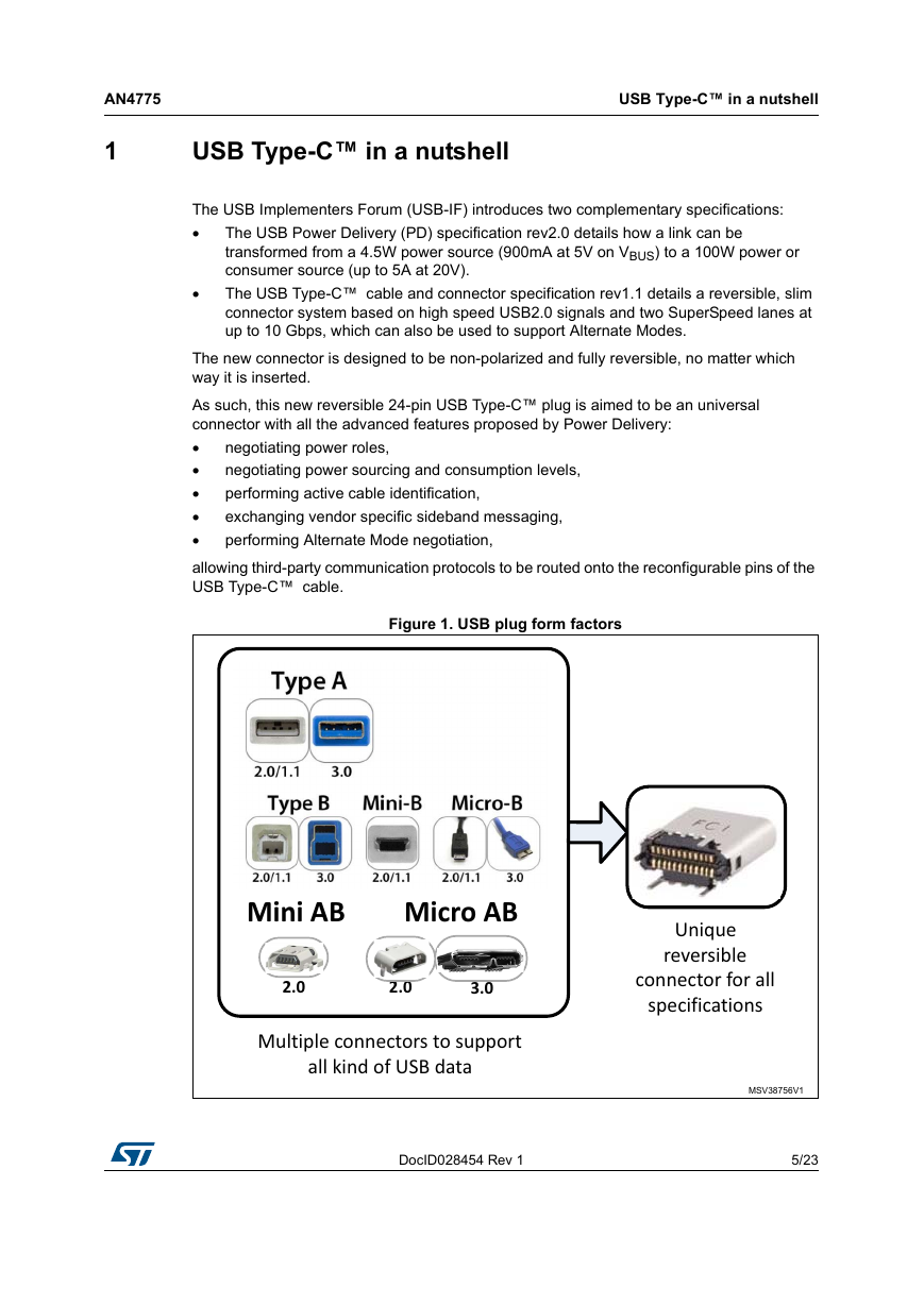
Figure 1. USB plug form factors
DocID028454 Rev 1
5/23
22
�
USB Type-C™ in a nutshell
AN4775
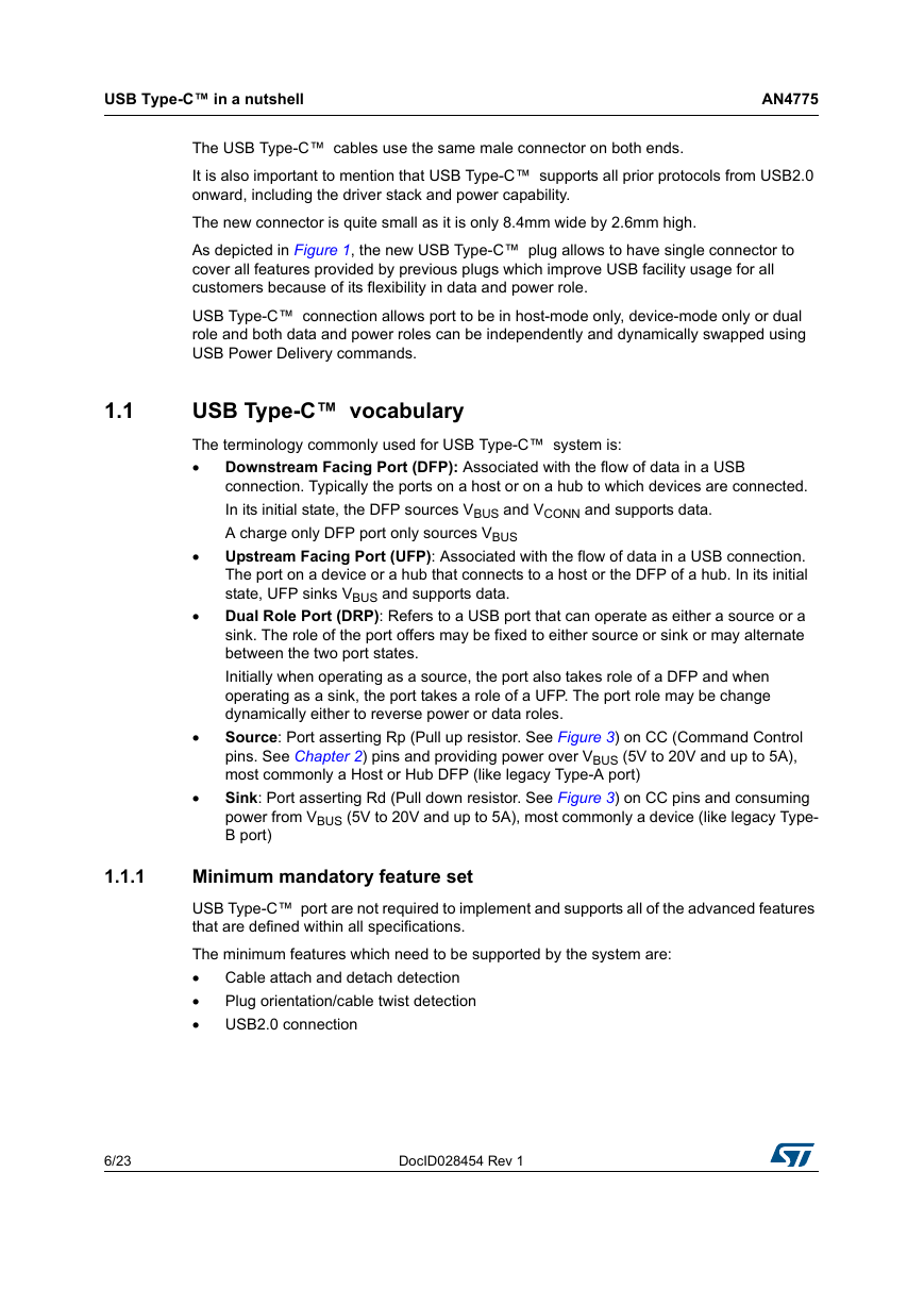
The USB Type-C™ cables use the same male connector on both ends.
It is also important to mention that USB Type-C™ supports all prior protocols from USB2.0
onward, including the driver stack and power capability.
The new connector is quite small as it is only 8.4mm wide by 2.6mm high.
As depicted in Figure 1, the new USB Type-C™ plug allows to have single connector to
cover all features provided by previous plugs which improve USB facility usage for all
customers because of its flexibility in data and power role.
USB Type-C™ connection allows port to be in host-mode only, device-mode only or dual
role and both data and power roles can be independently and dynamically swapped using
USB Power Delivery commands.
1.1
USB Type-C™ vocabulary
The terminology commonly used for USB Type-C™ system is:
Downstream Facing Port (DFP): Associated with the flow of data in a USB
connection. Typically the ports on a host or on a hub to which devices are connected.
In its initial state, the DFP sources VBUS and VCONN and supports data.
A charge only DFP port only sources VBUS
Upstream Facing Port (UFP): Associated with the flow of data in a USB connection.
The port on a device or a hub that connects to a host or the DFP of a hub. In its initial
state, UFP sinks VBUS and supports data.
Dual Role Port (DRP): Refers to a USB port that can operate as either a source or a
sink. The role of the port offers may be fixed to either source or sink or may alternate
between the two port states.
Initially when operating as a source, the port also takes role of a DFP and when
operating as a sink, the port takes a role of a UFP. The port role may be change
dynamically either to reverse power or data roles.
Source: Port asserting Rp (Pull up resistor. See Figure 3) on CC (Command Control
pins. See Chapter 2) pins and providing power over VBUS (5V to 20V and up to 5A),
most commonly a Host or Hub DFP (like legacy Type-A port)
Sink: Port asserting Rd (Pull down resistor. See Figure 3) on CC pins and consuming
power from VBUS (5V to 20V and up to 5A), most commonly a device (like legacy Type-
B port)
1.1.1
Minimum mandatory feature set
USB Type-C™ port are not required to implement and supports all of the advanced features
that are defined within all specifications.
The minimum features which need to be supported by the system are:
Cable attach and detach detection
Plug orientation/cable twist detection
USB2.0 connection
6/23
DocID028454 Rev 1
�
AN4775
1.2
Connector pin mapping
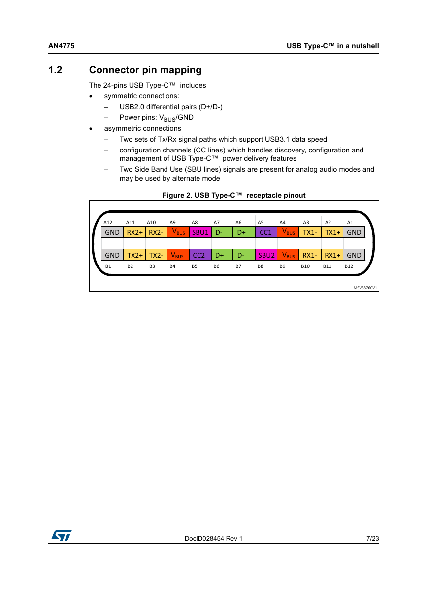
The 24-pins USB Type-C™ includes
USB2.0 differential pairs (D+/D-)
Power pins: VBUS/GND
symmetric connections:
–
–
asymmetric connections
–
–
USB Type-C™ in a nutshell
Two sets of Tx/Rx signal paths which support USB3.1 data speed
configuration channels (CC lines) which handles discovery, configuration and
management of USB Type-C™ power delivery features
Two Side Band Use (SBU lines) signals are present for analog audio modes and
may be used by alternate mode
–
Figure 2. USB Type-C™ receptacle pinout
DocID028454 Rev 1
7/23
22
�
USB Type-C™ in a nutshell
1.2.1
VBUS power options
AN4775
Name
GND
TX1+
TX1-
VBUS
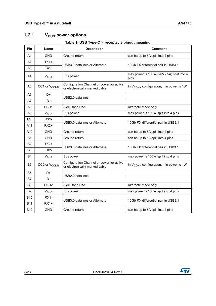
Table 1. USB Type-C™ receptacle pinout meaning
Description
Comment
Ground return
can be up to 5A split into 4 pins
USB3.0 datalines or Alternate
10Gb TX differential pair in USB3.1
Bus power
max power is 100W (20V - 5A) split into 4
pins
CC1 or VCONN
Configuration Channel or power for active
or electronically marked cable
In VCONN configuration, min power is 1W
D+
D-
SBU1
VBUS
RX2-
RX2+
GND
GND
TX2+
TX2-
VBUS
CC2 or VCONN
D+
D-
SBU2
VBUS
RX1-
RX1+
GND
USB2.0 datalines
Side Band Use
Bus power
Alternate mode only
max power is 100W split into 4 pins
USB3.0 datalines or Alternate
10Gb RX differential pair in USB3.1
Ground return
Ground return
can be up to 5A split into 4 pins
can be up to 5A split into 4 pins
USB3.0 datalines or Alternate
10Gb TX differential pair in USB3.1
Bus power
Configuration Channel or power for active
or electronically marked cable
max power is 100W split into 4 pins
In VCONN configuration, min power is 1W
USB2.0 datalines
Side Band Use
Bus power
Alternate mode only
max power is 100W split into 4 pins
USB3.0 datalines or Alternate
10Gb RX differential pair in USB3.1
Ground return
can be up to 5A split into 4 pins
Pin
A1
A2
A3
A4
A5
A6
A7
A8
A9
A10
A11
A12
B1
B2
B3
B4
B5
B6
B7
B8
B9
B10
B11
B12
8/23
DocID028454 Rev 1
�



 2023年江西萍乡中考道德与法治真题及答案.doc
 2012年重庆南川中考生物真题及答案.doc
 2013年江西师范大学地理学综合及文艺理论基础考研真题.doc
 2020年四川甘孜小升初语文真题及答案I卷.doc
 2020年注册岩土工程师专业基础考试真题及答案.doc
 2023-2024学年福建省厦门市九年级上学期数学月考试题及答案.doc
 2021-2022学年辽宁省沈阳市大东区九年级上学期语文期末试题及答案.doc
 2022-2023学年北京东城区初三第一学期物理期末试卷及答案.doc
 2018上半年江西教师资格初中地理学科知识与教学能力真题及答案.doc
 2012年河北国家公务员申论考试真题及答案-省级.doc
 2020-2021学年江苏省扬州市江都区邵樊片九年级上学期数学第一次质量检测试题及答案.doc
 2022下半年黑龙江教师资格证中学综合素质真题及答案.doc