关于 ITM
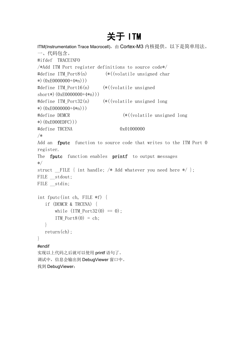
TRACEINFO
(*((volatile unsigned
(*((volatile unsigned long
(*((volatile unsigned char
ITM(Instrumentation Trace Macrocell),由 Cortex-M3 内核提供。以下是简单用法。
一、代码包含。
#ifdef
/*Add ITM Port register definitions to source code*/
#define ITM_Port8(n)
*)(0xE0000000+4*n)))
#define ITM_Port16(n)
short*)(0xE0000000+4*n)))
#define ITM_Port32(n)
*)(0xE0000000+4*n)))
#define DEMCR
*)(0xE000EDFC)))
#define TRCENA
/*
Add an
register.
The
*/
struct __FILE { int handle; /* Add whatever you need here */ };
FILE __stdout;
FILE __stdin;
function to source code that writes to the ITM Port 0
(*((volatile unsigned long
fputc
function enables
printf
to output messages
0x01000000
fputc
int fputc(int ch, FILE *f) {
if (DEMCR & TRCENA) {
while (ITM_Port32(0) == 0);
ITM_Port8(0) = ch;
}
return(ch);
}
#endif
实现以上代码之后就可以使用 printf 语句了。
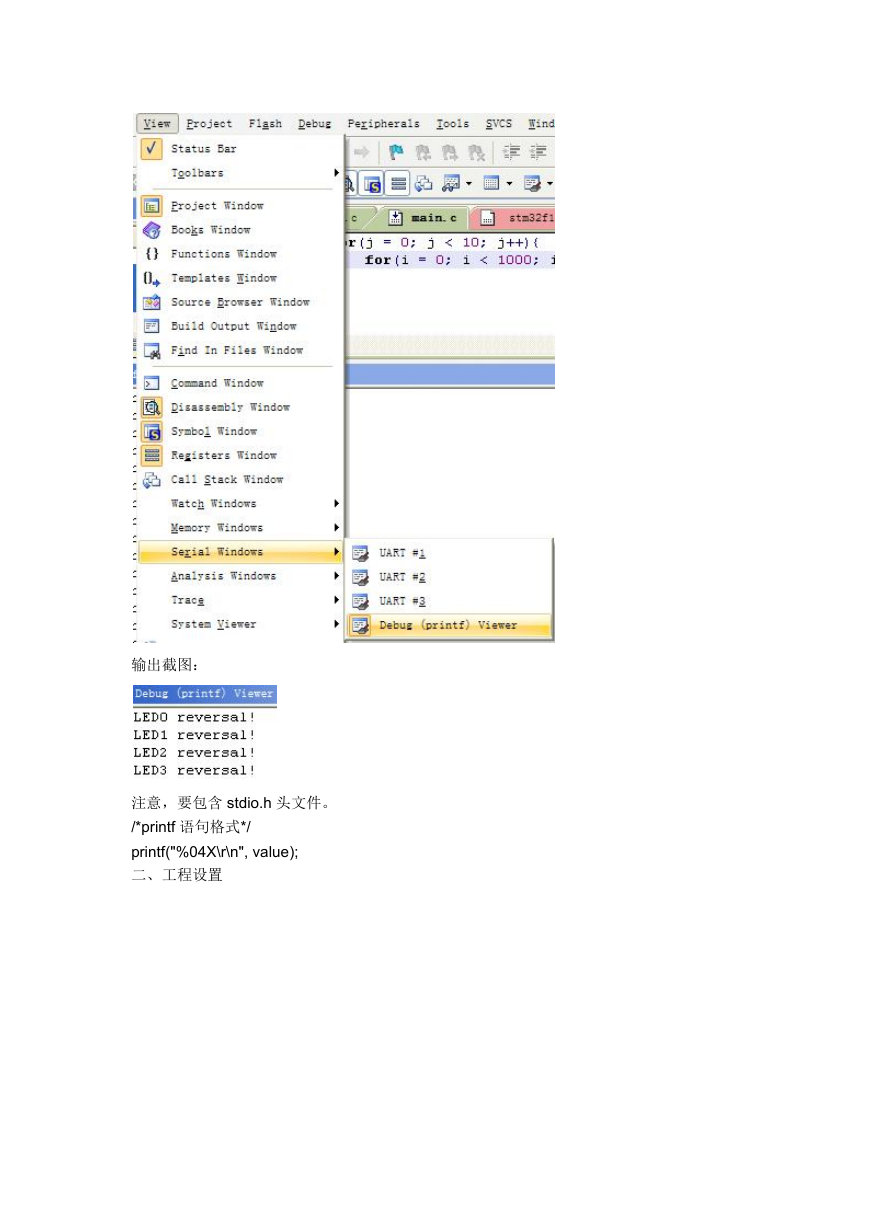
调试中,信息会输出到 DebugViewer 窗口中。
找到 DebugViewer:
�
输出截图:
注意,要包含 stdio.h 头文件。
/*printf 语句格式*/
printf("%04X\r\n", value);
二、工程设置
�
*/
编辑 STM32DBG.ini,内容如下:
/******************************************************************************/
/* STM32DBG.INI: STM32 Debugger Initialization File
/******************************************************************************/
// <<< Use Configuration Wizard in Context Menu >>>
/******************************************************************************/
/* This file is part of the uVision/ARM development tools.
*/
/* Copyright (c) 2005-2007 Keil Software. All rights reserved.
/* This software may only be used under the terms of a valid, current,
/* end user licence from KEIL for a compatible version of KEIL software
/* development tools. Nothing else gives you the right to use this software.
/******************************************************************************/
*/
//
*/
*/
*/
FUNC void DebugSetup (void) {
// Debug MCU Configuration
// DBG_SLEEP
// DBG_STOP
// DBG_STANDBY Debug Standby Mode
//
// TRACE_MODE
Debug Sleep Mode
Debug Stop Mode
TRACE_IOEN Trace I/O Enable
Trace Mode
�
<0=> Asynchronous
<1=> Synchronous: TRACEDATA Size 1
<2=> Synchronous: TRACEDATA Size 2
<3=> Synchronous: TRACEDATA Size 4
//
//
//
//
// DBG_IWDG_STOP Independant Watchdog Stopped when Core is
halted
// DBG_WWDG_STOP Window Watchdog Stopped when Core is halted
// DBG_TIM1_STOP Timer 1 Stopped when Core is halted
// DBG_TIM2_STOP Timer 2 Stopped when Core is halted
// DBG_TIM3_STOP Timer 3 Stopped when Core is halted
// DBG_TIM4_STOP Timer 4 Stopped when Core is halted
// DBG_CAN_STOP CAN Stopped when Core is halted
//
/*0xE0042004 为地址,0x00000027 中 2 为 DBGMCU_CR 的第六位,是 TRACE_IOEN
这一位必须为 1,那个 7 不懂*/
_WDWORD(0xE0042004, 0x00000027);
// DBGMCU_CR
}
DebugSetup();
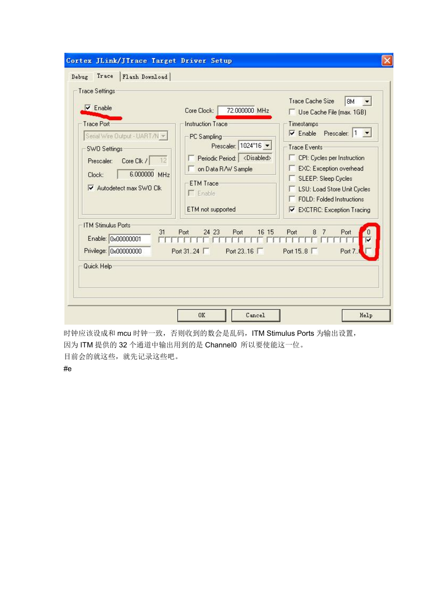
下一步,trace 的设置:
// Debugger Setup
�
时钟应该设成和 mcu 时钟一致,否则收到的数会是乱码,ITM Stimulus Ports 为输出设置,
因为 ITM 提供的 32 个通道中输出用到的是 Channel0 所以要使能这一位。
目前会的就这些,就先记录这些吧。
#e
�


 2023年江西萍乡中考道德与法治真题及答案.doc
 2012年重庆南川中考生物真题及答案.doc
 2013年江西师范大学地理学综合及文艺理论基础考研真题.doc
 2020年四川甘孜小升初语文真题及答案I卷.doc
 2020年注册岩土工程师专业基础考试真题及答案.doc
 2023-2024学年福建省厦门市九年级上学期数学月考试题及答案.doc
 2021-2022学年辽宁省沈阳市大东区九年级上学期语文期末试题及答案.doc
 2022-2023学年北京东城区初三第一学期物理期末试卷及答案.doc
 2018上半年江西教师资格初中地理学科知识与教学能力真题及答案.doc
 2012年河北国家公务员申论考试真题及答案-省级.doc
 2020-2021学年江苏省扬州市江都区邵樊片九年级上学期数学第一次质量检测试题及答案.doc
 2022下半年黑龙江教师资格证中学综合素质真题及答案.doc