logo资料库

VL53L0X中文数据手册.pdf

第1页 / 共26页
第2页 / 共26页
第3页 / 共26页
第4页 / 共26页
第5页 / 共26页
第6页 / 共26页
第7页 / 共26页
第8页 / 共26页
资料共26页,剩余部分请下载后查看
Figure 1. VL53L0X ranging sensor module
1 Overview
2 Initial customer manufacturing calibration
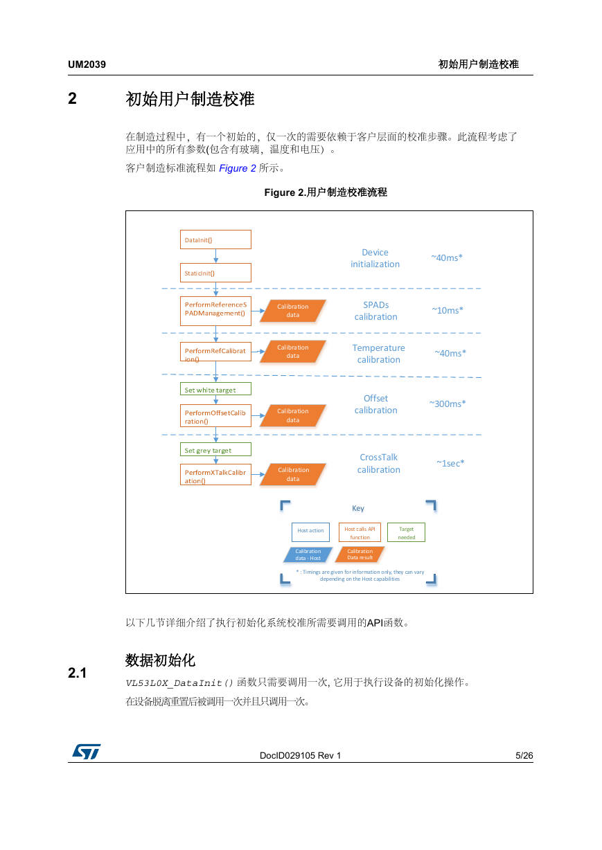
Figure 2. Customer manufacturing calibration flow
2.1 Data init
2.2 Static Init
2.3 Reference SPADs calibration
2.3.1 Reference SPADs calibration procedure
2.4 Ref (temperature) calibration
2.4.1 Ref calibration procedure
2.5 Offset calibration
2.5.1 Offset calibration procedure
2.6 Cross-talk calibration
2.6.1 Cover window impact on ranging
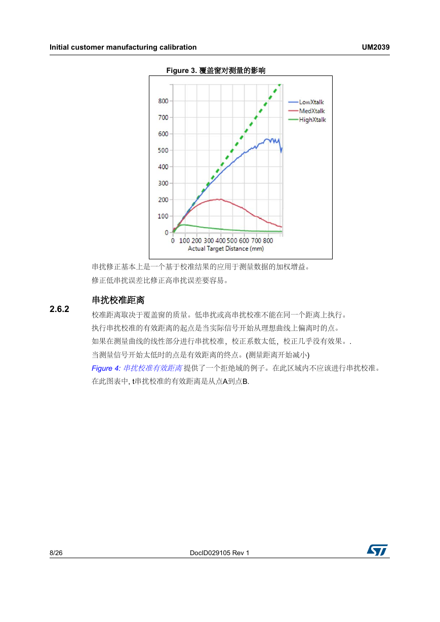
Figure 3. Cover window impact on ranging
2.6.2 Cross-talk calibration distance
Figure 4. Cross-talk calibration valid distances
2.6.3 Cross-talk calibration procedure
3 Range profile phases
3.1 Initialization/calibration phase
3.2 Ranging phase
Figure 5. Initialization flow
Figure 6. VL53L0X API ranging flow
4 System initialization/calibration
4.1 Data init
4.2 Static Init
4.3 Load calibration data
4.3.1 Reference SPADs
4.3.2 Ref calibration
4.3.3 Offset calibration
4.3.4 Cross-talk correction
4.4 Device mode
4.5 Polling and interrupt mode
5 Ranging
5.1 Start a measurement
5.1.1 Start measurement only
5.1.2 Start measurement and wait for data ready
5.1.3 Start measurement, wait for data ready and report the data
5.2 Stop a measurement
5.3 Get a result
5.3.1 Host polling to get the result status
5.3.2 Get measurement
Table 1. Range Status
6 API useful additional functions
6.1 Overall timing budget
6.2 Limit settings
Table 2. Default limit states and values
6.3 Timed ranging
6.4 API versions and product revision
6.5 API state and API error
Table 3. API state description
Table 4. API error values and error strings description
6.6 I2C device address
6.7 Reset
6.8 Interrupt settings
Table 5. Interrupt threshold behaviour
7 Example API range profiles
Table 6. Example API range profiles
7.1 High accuracy
7.2 Long range
7.3 High speed
8 Acronyms and abbreviations
Table 7. Acronyms and abbreviations
9 Revision history
Table 8. Document revision history
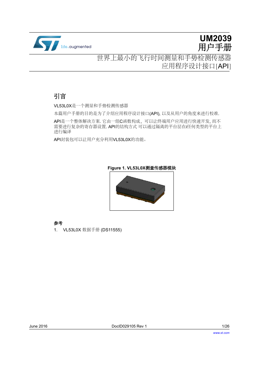
UM2039 用户手册 世界上最小的飞行时间测量和手势检测传感器 应用程序设计接口[API] 引言 VL53L0X是一个测量和手势检测传感器 本篇用户手册的目的是为了介绍应用程序设计接口(API), 以及从用户的角度来进行校准. API是一个整体解决方案. 它由一组C函数构成,可以让终端用户应用进行快速开发, 而不 需要进行复杂的寄存器设置. API的结构方式 可以通过隔离的平台层在i任何类型的平台上 进行编译 API封装包可以让用户充分利用VL53L0X的功能。 Figure 1. VL53L0X测量传感器模块 参考 1. VL53L0X 数据手册 (DS11555) June 2016 DocID029105 Rev 1 1/26 www.st.com 26
目录 目录 1 2 3 4 5 2/26 UM2039 概述 . . . . . . . . . . . . . . . . . . . . . . . . . . . . . . . . . . . . . . . . . . . . . . . . . . . . . . . 4 2.4 初始用户制造校准 . . .. . . . . . . . .. . . . . . . . .. . . . . . . . . . . . . . . . . . . . . . . . . 5 2.1 数据初始化 . . . . . . . . . . . . . . . . . . . . . . .. . . . . . . . . . . . . . . . . . . . . . . . . . 5 2.2 静态初始化 . . . . . . . . . . . . . . . . . . . . . . . . . . . . . . . . . . . . . . . . . . . . . . . . . 6 2.3 参考 SPADs 校准 . . . . . . . . . . . . . . . . . . . .. . . . . . . . . . . . . . . . . . . . . . . . 6 2.3.1 参考 SPADs 校准步骤 . . . . . . . . . . . . . . . . . . . . . . . . . . . . . . . . . . . . . . . 6 Ref (温度) 校准 . . . .. . . .. . . . .. . . . . . . . . . . . . . . . . . . . . . . . . . . . . . . . . . . 6 2.4.1 Ref 校准步骤. . . .. . . .. . . .. . . . . . . . . . . . . . . . . . . . . . . . . . . . . . . . . . . . . . . 7 2.5 偏移误差校准 . . . . . . . . . . . . . . . . . . . . . . . . . . . . . . . . . . . . . . . . . . . . 7 2.5.1 偏移误差校准步骤 . . . . . . . . .. . . . .. . . . . . . . . . . . . . . . . . . . . . . . . . . . . . 7 2.6 串扰校准. . . . .. . . . . . . . . . . . . . . . . . . . . . . . . . . . . . . . . . . . . . . . . . . .. . . . . 7 2.6.1 覆盖窗对测量的影响 . . . . . . . . . . . . .. . . . .. . . . . . . . . . . . . . . . . . . . . . . 7 2.6.2 串扰校准距离. . . . .. . . . .. . . . .. . . . . . . . . . . . . . . . . . . . . . . . . . . . . . . . . . . . 8 2.6.3 串扰校准步骤. . . . .. . . . .. . . . .. . . . . . . . . . . . . . . . . . . . . . . . . . . . . . . . . . . . 9 阶段范围简介 . . . . . . . . . . . .. . . .. . . . . . . . . . . . . . . . . . . . . . . . . . . . . . . . 10 3.1 初始化/校准 阶段 . . . . . . . . . . . . . . .. . . . . . . . . . . . . . . . . . . . . . . . . . . 10 3.2 测量阶段 . . . . . . . . . . . . . .. . . . . . . . . . . . . . . . . . . . . . . . . . . . . . . . . . . . 10 系统 初始值/校准值. . . . . . . . . . . . . . . . . . . . . . . . . . . . . . . . . . . . . . . . . . 13 4.1 数据初始化 . . . . . . . . . . . . . . . . . . . . . . . . . . . . . . . . . . . . . . . . . . . . . . . 13 4.2 静态初始化 . . . . . . . . . . . . . . . . . . . . . . . . .. . . . . . . . . . . . . . . . . . . . . . . . 13 4.3 加载校准值数据 . . . . . . . . . . . . . . . . . . . . . . . . . . . . . . . . . . . . . . . . . . . 13 4.3.1 参考 SPADs . . . . . . . . . . . . . . . .. . . . . . . . . . . . . . . . . . . . . . . . . . . . . 13 Ref 校准 . . . . . . . . . . . . . . . . . . . . . . . . . . . . . . . . . . . . . . . . . . . . . . . . 13 4.3.2 4.3.3 偏移误差校准 . . . . . . . . . . . . . . . . . . . . . . . . . . . . . . . . . . . . . . . . . . . . 13 4.3.4 串扰校准 . . . . . . . . . . . . . . . . . . . . . . . . . . . . . . . . . . . . . . . . . . . . . . . . 13 4.4 设备模式 . . . . . . . . . . . .. . . . . . . . . . . . . . . . . . . . . . . . . . . . . . . . . . . . . . 14 4.5 轮询和中断模式 . . . . . . . .. . .. . .. . . . . . . . . . . . . . . . . . . . . . . . . . . . . . . 14 测量 . . . . . . . . . . . . . . . . . . . . . . . . . . . . . . . . . . . . . . . . . . . . . . . . . . 15 5.1 开始一次测量 . . . . . . . . . . . . . . . . . .. . . . . . . . . . . . . . . . . . . . . . . . . . . . 15 DocID029105 Rev 1
UM2039 Contents 5.1.1 5.1.2 5.1.3 仅开始测量 . . . . . .. . . . . .. . . . . . . . . . . . . . . . . . . . . . . . . . . . . . . . . . . . 15 开始测量且等待数据准备就绪 . . .. . . . . .. . . . . . . . . . . . . . . . . . . . . . . . 15 开始测量,等待数据准备就绪并报告数据. . . . . .. . . . . .. . . . . .. . . . . . . . . 15 5.2 停止一次测量. . . . . . . . . . . . . . . . . . . . . . . . . . . . . . . . . . . . . . . . . . . . . . 15 5.3 取得结果 . . . . . . . . . . . . . . .. . . . . . . . . . . . . . . . . . . . . . . . . . . . . . . . . . . 16 主机轮询以获得结果状态 . . . . . . . . . . . . . . . . . . . . . . . . . . . . . . . . . . . . 16 取得测量结果 . . . . . . . . . . . . . . .. . . . . . . . . . . . . . . . . . . . . . . . . . . . . 16 5.3.1 5.3.2 6 7 8 9 API 有用的附加功能 . . . . . . . . . . . . . .. . . . . .. . . . . . . . . . . . . . . . . . . . . . . 17 6.1 总体时间预算 . . . . .. . . . .. . . . . . . . . . . . . . . . . . . . . . . . . . . . . . . . . . . . . 17 6.2 限制设置 . . . . . . . . .. . . . . . . . . . . . . . . . . . . . . . . . . . . . . . . . . . . . . . . . 17 6.3 定时测量 . . . . . . . . . . . . . .. . . . . . . . . . . . . . . . . . . . . . . . . . . . . . . . . . . . 18 API 版本和产品修订 . . . . . . . . . . . . . . . . . . . . . . . . . . . . . . . . . . . . . . . . . . 18 6.4 6.5 API 状态和API错误 . . . . . . . . .. . . . . . . . . . . . . . . . . . . . . . . . . . . . . . . . . 19 6.6 I2C 设备地址 . . . . . . . . . . . . . . . . .. . . . . . . . . . . . . . . . . . . . . . . . . . . . . . 20 6.7 复位 . . . . . . . . . .. . . . . . . . . . . . . . . . . . . . . . . . . . . . . . . . . . . . . . . . . . . 20 6.8 中断设置 . . . . . . . . . . . . . . . . . . . . . . . . . . . . . . . . . . . . . . . . . . . . . . . . . . 20 示例 API 模式配置 . . . . . .. . . . . . . . . . . . . . . . . . . . . . . . . . . . . . . . . . . . 22 7.1 高精度 . . . . . . . . .. . . . . . . . . . . . . . . . . . . . . . . . . . . . . . . . . . . . . . . . . . 22 7.2 长距离 . . . . . . . . . . . .. . . . . . . . . . . . . . . . . . . . . . . . . . . . . . . . . . . . . . . . 22 7.3 高速 . . . . . . . . . . . . . . . . . . . . . . . . . . . . . . . . . . . . . . . . . . . . . . . . . . . . . . 23 首字母缩写和缩写 . . . . .. . . . .. . . . .. . . . . . . . . . . . . . . . . . . . . . . . . . . . . . 24 修订历史 . . . . . . . . . . . . . . . . . . .. . .. . . . . . . . . . . . . . . . . . . . . . . . . . . . . 25 DocID029105 Rev 1 3/26 26
概述 1 Note: 概述 VL53L0X 的API是基于光子抽象层(PAL)描述的。 API 被定义为PAL的实现。 API 公开了用户用于控制设备的高等级函数。 完整的API,以API包的形式,以chm和pdf格式提供。 UM2039 4/26 DocID029105 Rev 1
UM2039 2 初始用户制造校准 初始用户制造校准 在制造过程中,有一个初始的,仅一次的需要依赖于客户层面的校准步骤。此流程考虑了 应用中的所有参数(包含有玻璃,温度和电压)。 客户制造标准流程如 Figure 2 所示。 Figure 2.用户制造校准流程 DataInit StaticInit Device initialization ~40ms* SPADs calibration ~10ms* Temperature calibration ~40ms* Offset calibration ~300ms* CrossTalk calibration ~1sec* Calibration data Calibration data Calibration data Calibration data Key Host calls API function Calibration Data result Host action Calibration data - Host Target needed * : Timings are given for information only, they can vary depending on the Host capabilities 以下几节详细介绍了执行初始化系统校准所需要调用的API函数。 2.1 数据初始化 VL53L0X_DataInit() 函数只需要调用一次, 它用于执行设备的初始化操作。 在设备脱离重置后被调用一次并且只调用一次。 DocID029105 Rev 1 5/26 26
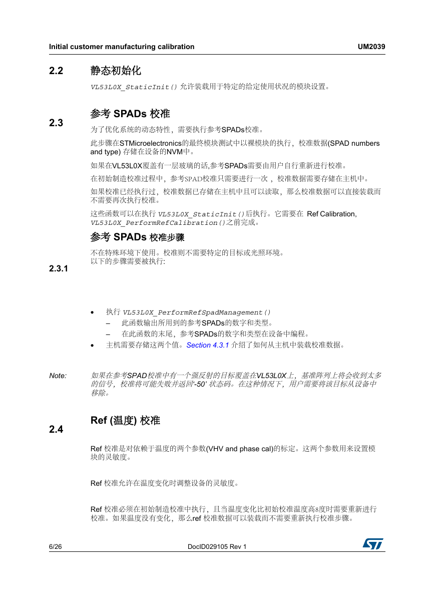
Initial customer manufacturing calibration UM2039 2.2 2.3 2.3.1 Note: 2.4 静态初始化 VL53L0X_StaticInit() 允许装载用于特定的给定使用状况的模块设置。 参考 SPADs 校准 为了优化系统的动态特性,需要执行参考SPADs校准。 此步骤在STMicroelectronics的最终模块测试中以裸模块的执行,校准数据(SPAD numbers and type) 存储在设备的NVM中。 如果在VL53L0X覆盖有一层玻璃的话,参考SPADs需要由用户自行重新进行校准。 在初始制造校准过程中,参考SPAD校准只需要进行一次 ,校准数据需要存储在主机中。 如果校准已经执行过,校准数据已存储在主机中且可以读取,那么校准数据可以直接装载而 不需要再次执行校准。 这些函数可以在执行 VL53L0X_StaticInit()后执行。它需要在 Ref Calibration, VL53L0X_PerformRefCalibration()之前完成。 参考 SPADs 校准步骤 不在特殊环境下使用。校准则不需要特定的目标或光照环境。 以下的步骤需要被执行: • 执行 VL53L0X_PerformRefSpadManagement() – 此函数输出所用到的参考SPADs的数字和类型。 – 在此函数的末尾,参考SPADs的数字和类型在设备中编程。 • 主机需要存储这两个值。Section 4.3.1 介绍了如何从主机中装载校准数据。 如果在参考SPAD校准中有一个强反射的目标覆盖在VL53L0X上,基准阵列上将会收到太多 的信号,校准将可能失败并返回‘-50’ 状态码。在这种情况下,用户需要将该目标从设备中 移除。 Ref (温度) 校准 Ref 校准是对依赖于温度的两个参数(VHV and phase cal)的标定。这两个参数用来设置模 块的灵敏度。 Ref 校准允许在温度变化时调整设备的灵敏度。 Ref 校准必须在初始制造校准中执行,且当温度变化比初始校准温度高8度时需要重新进行 校准。如果温度没有变化,那么ref 校准数据可以装载而不需要重新执行校准步骤。 6/26 DocID029105 Rev 1
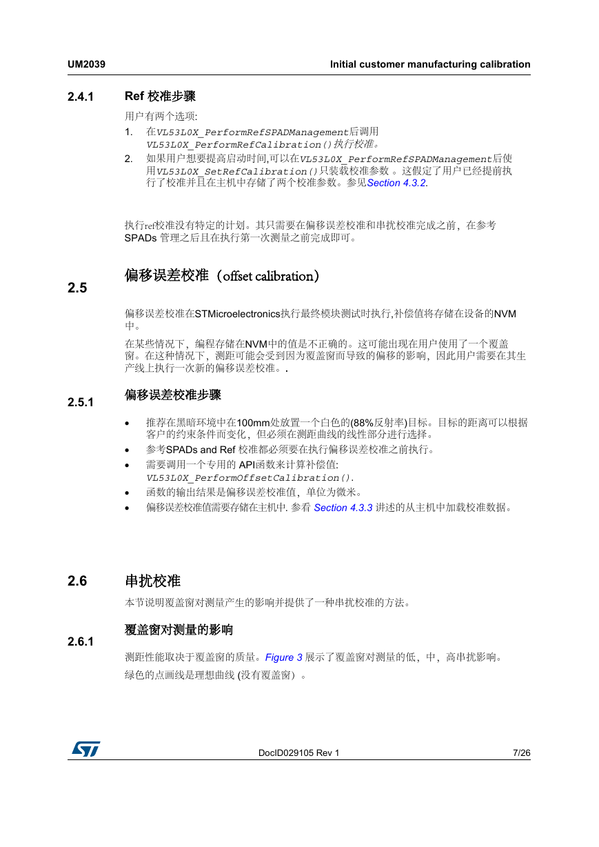
UM2039 2.4.1 Initial customer manufacturing calibration Ref 校准步骤 用户有两个选项: 1. 在VL53L0X_PerformRefSPADManagement后调用 VL53L0X_PerformRefCalibration()执行校准。 2. 如果用户想要提高启动时间,可以在VL53L0X_PerformRefSPADManagement后使 用VL53L0X_SetRefCalibration()只装载校准参数 。这假定了用户已经提前执 行了校准并且在主机中存储了两个校准参数。参见Section 4.3.2. 执行ref校准没有特定的计划。其只需要在偏移误差校准和串扰校准完成之前,在参考 SPADs 管理之后且在执行第一次测量之前完成即可。 偏移误差校准(offset calibration) 2.5 偏移误差校准在STMicroelectronics执行最终模块测试时执行,补偿值将存储在设备的NVM 中。 在某些情况下,编程存储在NVM中的值是不正确的。这可能出现在用户使用了一个覆盖 窗。在这种情况下,测距可能会受到因为覆盖窗而导致的偏移的影响,因此用户需要在其生 产线上执行一次新的偏移误差校准。. 2.5.1 偏移误差校准步骤 • 推荐在黑暗环境中在100mm处放置一个白色的(88%反射率)目标。目标的距离可以根据 客户的约束条件而变化,但必须在测距曲线的线性部分进行选择。 • 参考SPADs and Ref 校准都必须要在执行偏移误差校准之前执行。 • 需要调用一个专用的 API函数来计算补偿值: VL53L0X_PerformOffsetCalibration(). • 函数的输出结果是偏移误差校准值,单位为微米。 • 偏移误差校准值需要存储在主机中. 参看 Section 4.3.3 讲述的从主机中加载校准数据。 2.6 2.6.1 串扰校准 本节说明覆盖窗对测量产生的影响并提供了一种串扰校准的方法。 覆盖窗对测量的影响 测距性能取决于覆盖窗的质量。Figure 3 展示了覆盖窗对测量的低,中,高串扰影响。 绿色的点画线是理想曲线 (没有覆盖窗)。 DocID029105 Rev 1 7/26 26
Initial customer manufacturing calibration UM2039 Figure 3. 覆盖窗对测量的影响 2.6.2 串扰修正基本上是一个基于校准结果的应用于测量数据的加权增益。 修正低串扰误差比修正高串扰误差要容易。 串扰校准距离 校准距离取决于覆盖窗的质量。低串扰或高串扰校准不能在同一个距离上执行。 执行串扰校准的有效距离的起点是当实际信号开始从理想曲线上偏离时的点。 如果在测量曲线的线性部分进行串扰校准,校正系数太低,校正几乎没有效果。. 当测量信号开始太低时的点是有效距离的终点。(测量距离开始减小) Figure 4: 串扰校准有效距离 提供了一个拒绝域的例子。在此区域内不应该进行串扰校准。 在此图表中, t串扰校准的有效距离是从点A到点B. 8/26 DocID029105 Rev 1
分享到:
收藏