Introduction to USB 3.0
By Donovan (Don) Anderson, Vice President, MindShare, Inc.
This paper is a brief review of the USB 3.0 implementation, focusing on USB 2.0
backward compatibility and on the major features associated with the Super-
Speed (SS) bus. The goal is to provide the reader with a short and concise
description of USB 3.0, and enough detail to give a good feel for the technology,
protocols, and techniques.
Due to the limited scope of this paper, some terminology and concepts are intro-
duced but not fully developed. A MindShare Comprehensive USB 3.0 book is in
the works that will provide all of the details. In the meantime, please check our
website at www.mindshre.com to learn the availabiltity of our USB 3.0 classes
and eLearning courses.
Motivation for USB 3.0
USB 3.0 enables more demanding applications compared to USB 2.0 by address-
ing its limitations:
• Bandwidth - 5.0 Gb/sec SuperSpeed (SS) vs. 480 Mb/sec (High Speed) rate
Power Conservation - link power states (U0 - U3) and function power man-
agement
Data Flow Control - poll once versus poll multiple times
Error Handling - End-to-end and port-to-port error detection and retries
versus only end-to-end retries with USB 2.0.
The additional bandwidth provided by USB SS transactions can benefit applica-
tions like real-time audio and video streaming that require higher bus band-
width at regular intervals.
Mass storage applications can also benefit from the SS bandwidth. For example,
Table 1 lists approximate download times for the different transmission rates.
Visit MindShare Training at www.mindshare.com
1
�
Introduction to USB 3.0
Table 1: Download Speeds
SD Movie - 6GB
USB Flash 16GB HD Movie - 25GB
USB 1.0 (FS)
~ 2 hours
~ 6 hours
~ 9.25 hours
USB 2.0 (HS)
~ 3.25 minutes
~ 9 minutes
~ 14 minutes
USB 3.0 (SS)
~ 20 seconds
~ 54 seconds
~ 70 seconds
SD= Stanrdard Definition; HD = High Definition (Source: USB-IF)
USB 3.0 Topology
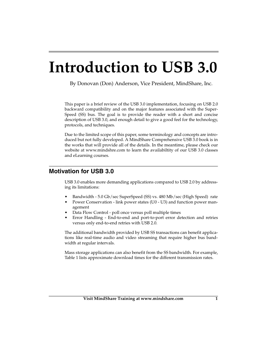
Figure 1 provides an example of a USB 3.0 topology. A major feature of this
topology is its support of all wired USB speeds (LS, FS, HS & SS), and this is
accomplished via the two separate buses that are integrated into USB 3.0 cables,
connectors and hubs. In the illustration, the SS bus is represented in red and
consists of two differential signal pairs, one to transmit packets and one to
receive. The standard USB 2.0 bus consists of a single differential pair that oper-
ates in a half-duplex model. Notice also that SS devices connect to both the SS
and USB 2.0 buses, and provide backward compatibility with older platforms
that don’t support SS.
2
Visit MindShare Training at www.mindshare.com
�
Introduction to USB 3.0
Figure 1: Example USB 3.0 Topology
CPU
Host Bridge
DRAM
HS
USB Host Controller
SS
FS Hub
SS
HS
SS
HS
LS
FS
SS
HS
SS
LS
SuperSpeed Links
High-Speed Links
Full-Speed Links
Low-Speed Links
SS
HS Hub
LS
HS
FS
Visit MindShare Training at www.mindshare.com
3
�
Introduction to USB 3.0
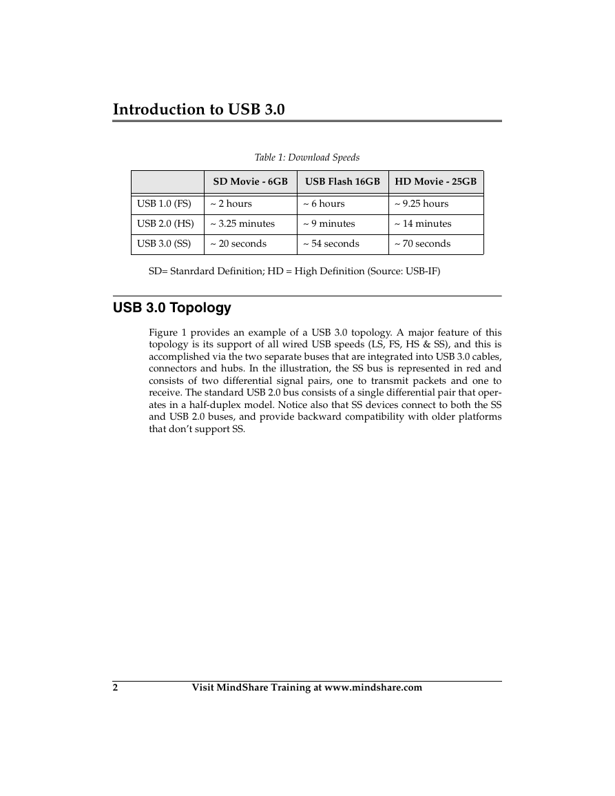
Figure 2 depicts the cross-section of a USB 3.0 cable and illustrates the SS and
USB 2.0 buses along with the VBUS power pin that supplies power at 5 vdc and
up to 900mA.
The SS bus employs a dual-simplex approach that allows simultaneous trans-
mission and reception of packets. There are many cases where an SS device may
be both transmitting and receiving data at the same time. For example, during
burst transactions a device may be receiving data from the host and returning
acknowledgements associated with data already received.
Figure 2: USB 3.0 Cable
USB 3.0 Composite Cable
Jacket
Braid
GND
VBus
D+
D-
SSTX+
SSTX-
SSRX+
SSRX-
USB 2.0
UTP
UTP
VBus
SDP
GND
SDP
SSTX, SSRX SDPs
W/Drain (2 Sets)
GND
VBus
D+
D-
USB 2.0 Tx/Rx
Differential pair (UTP)
SSRX+
SSRX-
SSTX+
SSTX-
USB 3.0 SuperSpeed
Rx Differential pair (SDP)
USB 3.0 SuperSpeed
Tx Differential pair (SDP)
USB 2.0 Links Versus SuperSpeed Links
Unlike the USB 2.0 bus, SS links are constantly transmitting and receiving traffic
to maintain synchronization in preparation for delivering the next packet. Each
SS link must be trained at startup so the receivers can establish bit lock at the 5.0
4
Visit MindShare Training at www.mindshare.com
�
Introduction to USB 3.0
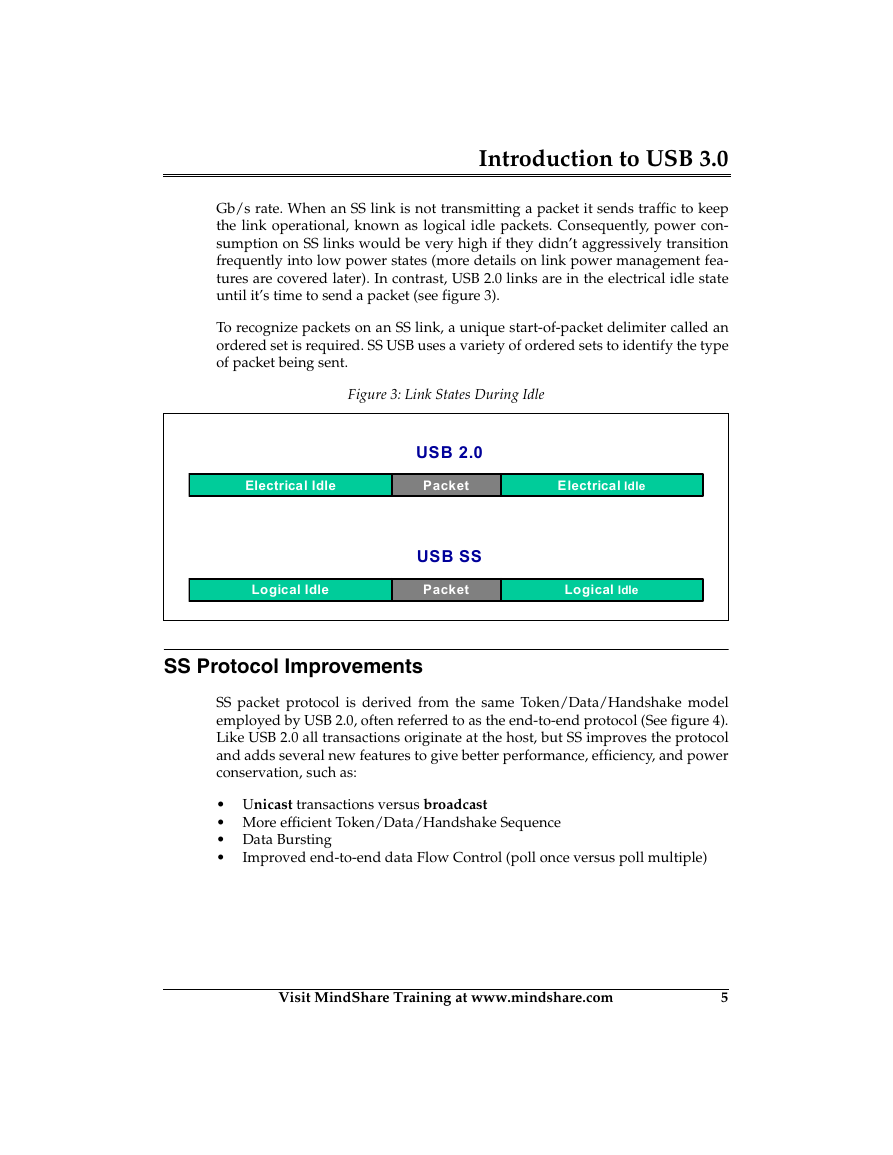
Gb/s rate. When an SS link is not transmitting a packet it sends traffic to keep
the link operational, known as logical idle packets. Consequently, power con-
sumption on SS links would be very high if they didn’t aggressively transition
frequently into low power states (more details on link power management fea-
tures are covered later). In contrast, USB 2.0 links are in the electrical idle state
until it’s time to send a packet (see figure 3).
To recognize packets on an SS link, a unique start-of-packet delimiter called an
ordered set is required. SS USB uses a variety of ordered sets to identify the type
of packet being sent.
Figure 3: Link States During Idle
Electrical Idle
Logical Idle
USB 2.0
Packet
USB SS
Packet
Electrical Idle
Logical Idle
SS Protocol Improvements
SS packet protocol is derived from the same Token/Data/Handshake model
employed by USB 2.0, often referred to as the end-to-end protocol (See figure 4).
Like USB 2.0 all transactions originate at the host, but SS improves the protocol
and adds several new features to give better performance, efficiency, and power
conservation, such as:
Unicast transactions versus broadcast
More efficient Token/Data/Handshake Sequence
Data Bursting
Improved end-to-end data Flow Control (poll once versus poll multiple)
Visit MindShare Training at www.mindshare.com
5
�
Introduction to USB 3.0
Unicast Transactions
SS transactions are routed directly from a root port to the target device, so only
links in the direct path between the root port and target device see the traffic.
That lets other links in the topology to enter or remain in a low power state. Fig-
ure 4 illustrates the direct routing used when forwarding packets from the host
to a target device.
Figure 4: Unicast Transactions
CPU
Host Bridge
DRAM
HS
USB Host Controller
SS
SS
HS
SS
SS
SS
HS
SS
SS
HS
SS
LS
SS
HS Hub
Token / Data / Handshake Sequences
An mentioned earlier, the SS end-to-end protocol is based on the standard USB
2.0 “Token/Data/Handshake” sequence. This section illustrates the differences
between the USB 2.0 and SS implementations through an IN and OUT example.
6
Visit MindShare Training at www.mindshare.com
�
Introduction to USB 3.0
IN Transaction Examples
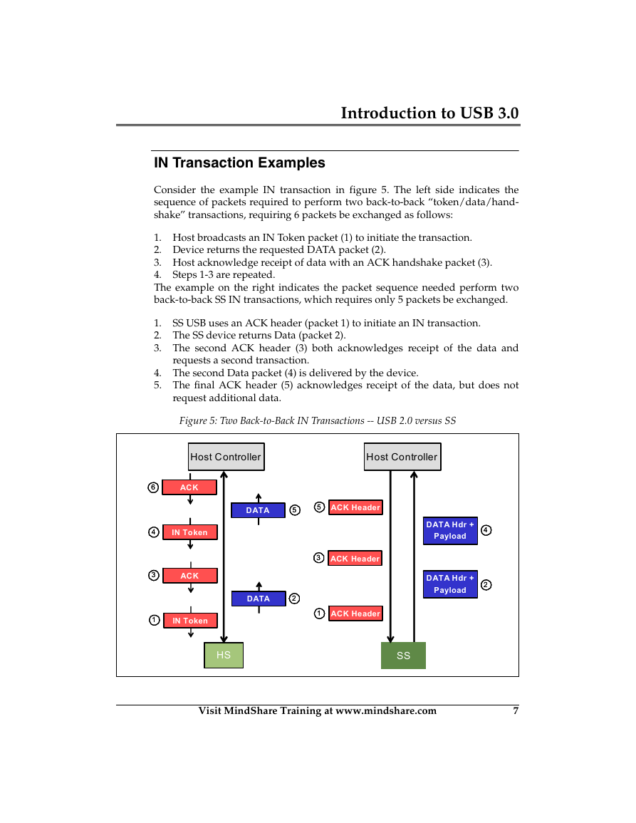
Consider the example IN transaction in figure 5. The left side indicates the
sequence of packets required to perform two back-to-back “token/data/hand-
shake” transactions, requiring 6 packets be exchanged as follows:
1. Host broadcasts an IN Token packet (1) to initiate the transaction.
2. Device returns the requested DATA packet (2).
3. Host acknowledge receipt of data with an ACK handshake packet (3).
4.
The example on the right indicates the packet sequence needed perform two
back-to-back SS IN transactions, which requires only 5 packets be exchanged.
Steps 1-3 are repeated.
SS USB uses an ACK header (packet 1) to initiate an IN transaction.
1.
2. The SS device returns Data (packet 2).
3. The second ACK header (3) both acknowledges receipt of the data and
requests a second transaction.
4. The second Data packet (4) is delivered by the device.
5. The final ACK header (5) acknowledges receipt of the data, but does not
request additional data.
Figure 5: Two Back-to-Back IN Transactions -- USB 2.0 versus SS
Host Controller
Host Controller
66
44
33
ACK
IN Token
ACK
11
IN Token
DATA
55
55
ACK Header
33
ACK Header
DATA
22
11
ACK Header
DATA Hdr +
Payload
DATA Hdr +
Payload
44
22
HSHS
SSSS
Visit MindShare Training at www.mindshare.com
7
�
Introduction to USB 3.0
OUT Transaction Examples
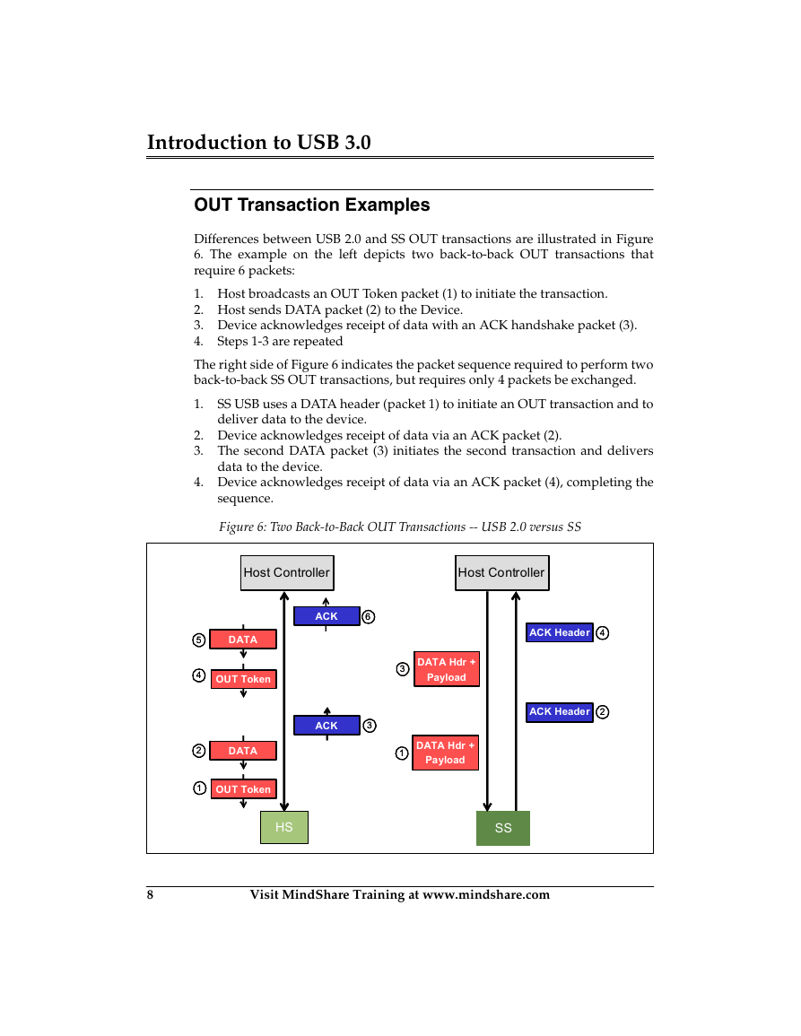
Differences between USB 2.0 and SS OUT transactions are illustrated in Figure
6. The example on the left depicts two back-to-back OUT transactions that
require 6 packets:
1. Host broadcasts an OUT Token packet (1) to initiate the transaction.
2. Host sends DATA packet (2) to the Device.
3. Device acknowledges receipt of data with an ACK handshake packet (3).
4.
The right side of Figure 6 indicates the packet sequence required to perform two
back-to-back SS OUT transactions, but requires only 4 packets be exchanged.
1.
SS USB uses a DATA header (packet 1) to initiate an OUT transaction and to
deliver data to the device.
Steps 1-3 are repeated
2. Device acknowledges receipt of data via an ACK packet (2).
3. The second DATA packet (3) initiates the second transaction and delivers
4. Device acknowledges receipt of data via an ACK packet (4), completing the
data to the device.
sequence.
Figure 6: Two Back-to-Back OUT Transactions -- USB 2.0 versus SS
Host Controller
Host Controller
ACK
66
ACK
33
33
DATA Hdr +
Payload
11
DATA Hdr +
Payload
ACK Header
44
ACK Header
22
55
44
22
11
DATA
OUT Token
DATA
OUT Token
HSHS
SSSS
8
Visit MindShare Training at www.mindshare.com
�



 2023年江西萍乡中考道德与法治真题及答案.doc
 2012年重庆南川中考生物真题及答案.doc
 2013年江西师范大学地理学综合及文艺理论基础考研真题.doc
 2020年四川甘孜小升初语文真题及答案I卷.doc
 2020年注册岩土工程师专业基础考试真题及答案.doc
 2023-2024学年福建省厦门市九年级上学期数学月考试题及答案.doc
 2021-2022学年辽宁省沈阳市大东区九年级上学期语文期末试题及答案.doc
 2022-2023学年北京东城区初三第一学期物理期末试卷及答案.doc
 2018上半年江西教师资格初中地理学科知识与教学能力真题及答案.doc
 2012年河北国家公务员申论考试真题及答案-省级.doc
 2020-2021学年江苏省扬州市江都区邵樊片九年级上学期数学第一次质量检测试题及答案.doc
 2022下半年黑龙江教师资格证中学综合素质真题及答案.doc