Mechatronics 47 (2017) 37–48
Contents lists available at ScienceDirect
Mechatronics
journal homepage: www.elsevier.com/locate/mechatronics
Impedance control of series elastic actuators: Passivity and
R
acceleration-based control
∗
Andrea Calanca
, Riccardo Muradore , Paolo Fiorini
Department of Computer Science, University of Verona, Strada Le Grazie 15, 37134 Verona, Italy
a r t i c l e
i n f o
a b s t r a c t
Article history:
Received 6 April 2017
Revised 5 August 2017
Accepted 20 August 2017
Available online 8 September 2017
Keywords:
Series elastic actuators
Impedance control
Passivity
Acceleration-based control
1. Introduction
Series elastic joints allow force and impedance controllers to be implemented on high torque and high
power density motors. Several impedance controllers have been proposed whose stability is usually an-
alyzed by means of passivity-based tools such as the Z -width characterization. This paper proposes an
overview of existing impedance control solutions for series elastic joints and derives the passivity char-
acterizations that are still missing in the literature, thus providing a complete and coherent overview
of the existing solutions. Within this overview, we highlight the advantages of impedance control based
on positive acceleration feedback showing improved stability robustness and impedance accuracy with
respect to existing solutions. These advantages are theoretically motivated (considering ideal conditions)
and experimentally validated.
© 2017 Elsevier Ltd. All rights reserved.
Series elastic actuators (SEA’s) are an emerging technology to
achieve high fidelity force control of high power density motors
[1] . In fact, series compliance can dramatically improve explicit
force control robustness [2,3] . Series elastic joints have been suc-
cessfully applied to humanoid robots (e.g. NASA’s Valkyrie [4] , Vir-
ginia Tech’s THOR [5] and IIT’s COMAN [6] ), quadrupeds (e.g. ETH’
s StarlETH [7] ), modern rehabilitation and assistive robotics [8–
11] and cooperative robots (e.g. RethinkRobotics Baxter [12] ). Most
of these applications are based on impedance control and need to
deliver forces with a high level of safety and accuracy. While safety
is a primary need for robots that interact with humans or with un-
structured environments, the demand for high accuracy is increas-
ing only recently. As an example, this requirement is pushed by
novel haptic interfaces which have been proposed in the last years.
Among others, Basafa et al. designed a haptic laparoscopic device
with three degrees of freedom actuated by SEA’s [13] ; Zinn et al.
proposed a haptic interface with large workspace based on the Dis-
tributed Macro-Mini concept where the macro actuation is given
by SEA’s [14] ; Oblack et al. proposed a multi-purpose rehabilitation
haptic device using series visco-elastic actuators [15] ; Parietti et al.
R
This paper was recommended for publication by Editor-in-Chief is Proof. Reza
Moheimani.
∗
Corresponding author.
E-mail addresses: andrea.calanca@univr.it , andrea.calanca@gmail.com (A.
Calanca), riccardo.muradore@univr.it (R. Muradore), paolo.fiorini@univr.it (P.
Fiorini).
http://dx.doi.org/10.1016/j.mechatronics.2017.08.010
0957-4158/© 2017 Elsevier Ltd. All rights reserved.
designed a haptic device with a series visco-elastic elements for
very fine force rendering, in the range of the human sensory accu-
racy [16] . In these haptic devices, the choice of SEA’s has been usu-
ally motivated by the decoupling effect of the series spring which
allows to mask the motor inertia and allows the accurate rendering
of even very low forces. Differently from traditional haptic inter-
faces, existing impedance controllers for SEA’s make use of explicit
force feedback, meaning that the force is explicitly measured and
fed back to the control system. This is because implicit force con-
trol (where the force is delivered in open loop by controlling the
motor current) cannot mask the motor inertia and cannot damp
the series spring oscillations.
The control problem of physical interaction (with humans or
with unstructured environments) involving explicit force feedback
is considered a hard challenge in robotics. Most of the proposed
solutions are based on the passivity interaction paradigm, which
provides a high level of stability robustness [17] . In particular pas-
sivity of the controlled robot is a sufficient and necessary condi-
tion to guarantee a stable interaction with any passive environ-
ment [18] including humans who are usually assumed as passive
systems [19] . Consequently several passivity-based control (PBC)
algorithms have been proposed to shape the output impedance
or the output force of SEA’s. The first passive force controller for
SEA’s was proposed by Pratt and Williamson [1] . Their solution
is based on acceleration feedback that forces the motor to have
the same acceleration of the environment, thus compensating for
load motion and leading to robust performance, i.e. predictable
error dynamics. Quite surprising this important feature was not
�
38
A. Calanca et al. / Mechatronics 47 (2017) 37–48
explicitly highlighted neither in the original work nor in the fol-
lowing literature which has been focused more on stability robust-
ness rather than performance robustness. Another investigation on
PBC of SEA’s has been conducted by Vallery et al. where a veloc-
ity sourced impedance control schema was considered [20] . They
found out that “SEA cannot display a higher pure stiffness than
the spring stiffness if passivity is desired”. Thus the spring design
cannot be arbitrarily compliant but must be tailored to the max-
imum desired stiffness leading to a trade-off between force con-
trol robustness (which requires compliance) and the maximum dis-
playable stiffness.
One of the outcomes of the research described in this paper
is to show that the same limitation highlighted by Vallery et al.
holds for several existing control architectures: admittance con-
trol [21] , impedance control [22] and parallel force-position control
[23] . The admittance control architecture was proposed by Pratt
et al. to reduce the force control bandwidth requirement in high
impedance rendering [21] . We will show that even this algorithm
cannot passively render a stiffness higher than the stiffness of the
physical spring. A similar outcome emerges by analyzing the pas-
sive impedance control of the DLR lightweight arm where a paral-
lel force-position architecture is implemented [23] .
In conclusion, we will show that at the current state of the art
there exist no passive algorithms that allow to overcome the physical
spring stiffness. Further limitations arise when a virtual Voigt model
impedance is desired, i.e. the parallel of a spring and a damper. For
example an impedance controlled SEA with velocity controlled mo-
tor cannot passively display a pure Voigt model [24] and we will
show that the same result holds for other control architectures.
Thus, the first contribution of this work is to derive missing pas-
sivity conditions for existing impedance control architectures pro-
viding a coherent framework of passivity results.
The second contribution is a novel algorithm that allows in the-
ory to passively overcome the physical spring stiffness and to pas-
sively display a pure Voigt model. This algorithm is inspired by the
seminal work by Pratt and Williamson [1] who used load acceler-
ation feedback to control the SEA output force and to cancel out
the influence of load dynamics in force control. We will formally
show that by taking advantage of load dynamics cancellation it is
possible to passively render any passive impedance. The intuition
behind this approach is that by exactly compensating for the load
motion, load (or environment) uncertainties disappear. In partic-
ular we refer to (perfect) load motion compensation as the ability
to move the motor homokinetically with the load or the environ-
ment. Thus load motion compensation is a way to obtain virtual
backdrivability, i.e. to backdrive a non-backdrivable motor by con-
trol. Indeed, the force to accelerate the motor is transferred to the
motor input by control and it is used to compensate for the motor
inertia. In the past, the concept of load motion compensation has
been already discussed in the force control literature and a generic
framework of solutions is presented in [25] . However, the effects
on impedance rendering and passivity have never been analyzed.
Other examples of SEA’s force control where the load dynamics is
explicitly taken into account includes disturbance observer archi-
tectures [4,26–28] , adaptive [29,30] , robust [31] and sliding-mode
[32] controllers. However, none of these works investigates the ef-
fect of load motion compensation on impedance rendering. We
highlight that the terms “load” and “environment” can be often
considered as equivalent: they both refer to the dynamics the SEA
or the robot is in contact with. A typical case is physical human-
robot interaction (pHRI) where the environment include or is iden-
tified with the human.
To address the issues described above, the paper is organized
as follows. To introduce the reader, Section 2 summarizes exist-
ing impedance control algorithms for SEA’s. Section 3 derives pas-
sivity conditions that are currently missing in the literature and
provides a summary and easy-to-compare view of passivity results.
Section 4 proposes a novel impedance control algorithm based on
positive acceleration feedback. Section 5 experimentally compares
the existing algorithms to our solution from the point of view of
stability robustness and impedance accuracy. Finally, conclusions
are drawn in Section 6 .
2. Impedance control of series elastic actuators
Impedance control aims at shaping the dynamical relation be-
tween the actuator position (or velocity) and applied external
forces. Impedance control can be implemented using an inner force
loop and an outer position loop or using the dual configuration:
an inner position loop and an outer force loop. The latter case is
usually called admittance control. In both architectures the desired
impedance/admittance is implemented in the outer loop while the
inner loop must be fast enough to have negligible dynamics [33] .
∈
L 2 e
An impedance relation mapping the velocity u
into the
or equivalently an admittance relation mapping the
∈
L 2 e
into the velocity y
is passive if there exists a con-
∈
L 2 e
force y
∈
force u
L 2 e
β such that
stant
≥ β,
T
∀
u ∈ L 2 e
,
∀
≥ 0
0
T
dt
(t )
(t )
u
y
(1)
−β represents the initial system energy [18,34] . If we con-
where
sider that ( u , y ) is a flow and effort pair we have that the system
output energy will never be greater than its input energy, over an
=
arbitrary observation time starting from t
0. The passive interac-
tion paradigm is based on the assumption that the environment is
a passive system and on the fact that negative feedback connection
of passive systems is still passive, thus stable.
Passivity of impedance controllers depends on several factors:
the control architecture, the inherent system dynamics and the de-
sired impedance. In particular, given a control algorithm applied
to a system, the set of impedance values that can be passively
rendered is called Z -width [35] . Established results in PBC liter-
ature show that the controlled system dynamics cannot be too
far from the inherent system dynamics [36] . In particular, Colgate
et al. found that the virtual inertia of a current controlled motor
cannot be reduced beyond one half of its physical inertia, using
non-collocated proportional force feedback [17] . Similarly, Vallery
et al. showed that the virtual stiffness of a SEA cannot be increased
over the physical spring stiffness, considering a velocity sourced
impedance control architecture [20] .
Hereafter, several impedance control schemas are reported and
their passivity is analyzed. We will start by introducing the com-
mon modeling and notation where linear and rotary quantities are
regarded as equivalent.
2.1. Modeling
The following SEA model is considered
=
(θ − q
)
k
τe
(2)
¨θ =
J
− τe
τm
(3)
τ e is the spring force exerted on the environment (or torque
where
θ is the motor position, q is the joint
in the case of a rotary joint),
τ m is the (current-controlled) motor input force (or
position and
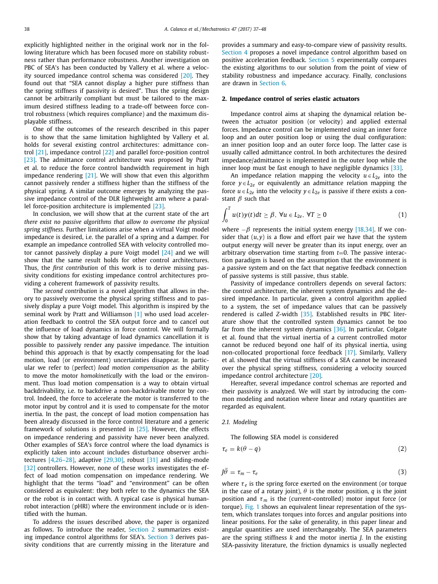
torque). Fig. 1 shows an equivalent linear representation of the sys-
tem, which translates torques into forces and angular positions into
linear positions. For the sake of generality, in this paper linear and
angular quantities are used interchangeably. The SEA parameters
are the spring stiffness k and the motor inertia J . In the existing
SEA-passivity literature, the friction dynamics is usually neglected
�
A. Calanca et al. / Mechatronics 47 (2017) 37–48
39
Fig. 1. A model of linear SEA interacting with an environment. Equivalent linear
representation which translates torques into forces and angular positions into linear
positions.
Table 1
Acronyms.
Acronyms Meaning
SEA
PBC
VM
∼ VM
BIC
VSIC
CAC
CIC
AB
Series elastic actuator
Passivity-based control
Voigt model
Approximated VM
Basic Impedance Control
Velocity-Sourced Impedance Control
Collocated Admittance Control
Collocated Impedance Control
Acceleration-based
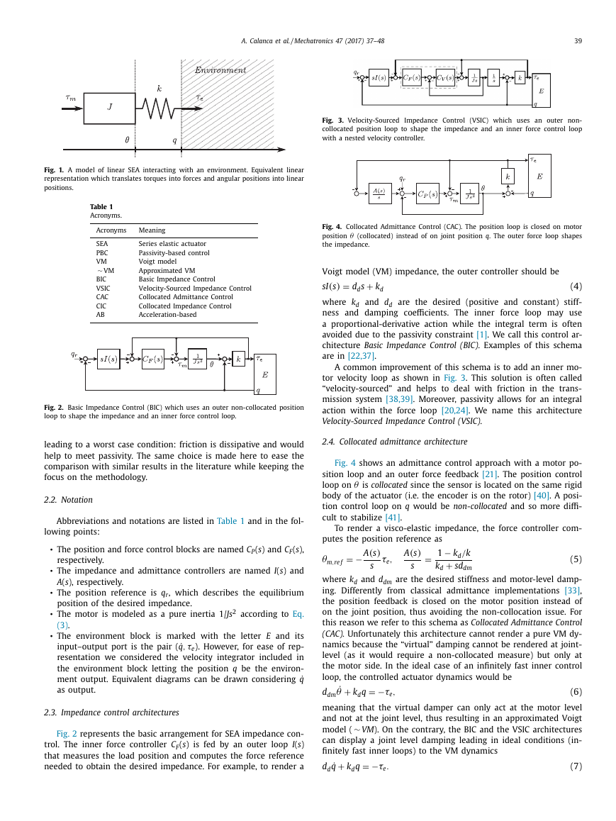
Fig. 2. Basic Impedance Control (BIC) which uses an outer non-collocated position
loop to shape the impedance and an inner force control loop.
leading to a worst case condition: friction is dissipative and would
help to meet passivity. The same choice is made here to ease the
comparison with similar results in the literature while keeping the
focus on the methodology.
2.2. Notation
Abbreviations and notations are listed in Table 1 and in the fol-
lowing points:
•
•
•
•
•
The position and force control blocks are named C P ( s ) and C F ( s ),
respectively.
The impedance and admittance controllers are named I ( s ) and
A ( s ), respectively.
The position reference is q r , which describes the equilibrium
position of the desired impedance.
The motor is modeled as a pure inertia 1/ Js
2 according to Eq.
(3) .
The environment block is marked with the letter E and its
τe ). However, for ease of rep-
,
input–output port is the pair ( ˙ q
resentation we considered the velocity integrator included in
the environment block letting the position q be the environ-
ment output. Equivalent diagrams can be drawn considering ˙ q
as output.
2.3. Impedance control architectures
Fig. 2 represents the basic arrangement for SEA impedance con-
trol. The inner force controller C F ( s ) is fed by an outer loop I ( s )
that measures the load position and computes the force reference
needed to obtain the desired impedance. For example, to render a
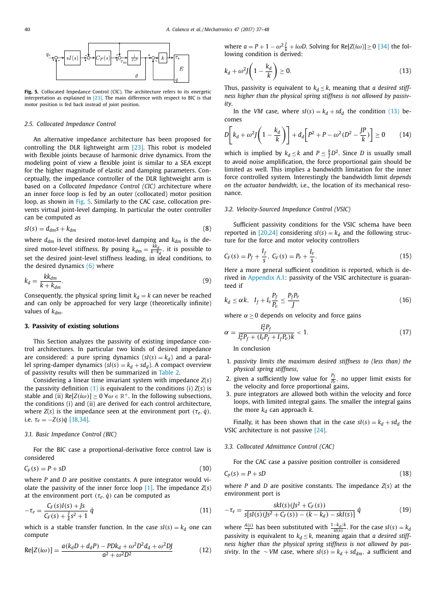
Fig. 3. Velocity-Sourced Impedance Control (VSIC) which uses an outer non-
collocated position loop to shape the impedance and an inner force control loop
with a nested velocity controller.
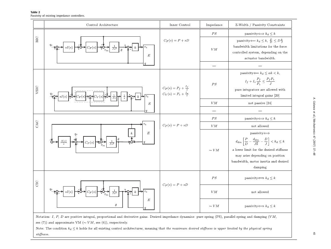
Fig. 4. Collocated Admittance Control (CAC). The position loop is closed on motor
θ (collocated) instead of on joint position q . The outer force loop shapes
position
the impedance.
Voigt model (VM) impedance, the outer controller should be
sI(s
)
=
+
k d
d d s
(4)
and d d
where k d
are the desired (positive and constant) stiff-
ness and damping coefficients. The inner force loop may use
a proportional-derivative action while the integral term is often
avoided due to the passivity constraint [1] . We call this control ar-
chitecture Basic Impedance Control (BIC). Examples of this schema
are in [22,37] .
A common improvement of this schema is to add an inner mo-
tor velocity loop as shown in Fig. 3 . This solution is often called
“velocity-sourced” and helps to deal with friction in the trans-
mission system [38,39] . Moreover, passivity allows for an integral
action within the force loop [20,24] . We name this architecture
Velocity-Sourced Impedance Control (VSIC).
2.4. Collocated admittance architecture
Fig. 4 shows an admittance control approach with a motor po-
sition loop and an outer force feedback [21] . The position control
θ is collocated since the sensor is located on the same rigid
loop on
body of the actuator (i.e. the encoder is on the rotor) [40] . A posi-
tion control loop on q would be non-collocated and so more diffi-
cult to stabilize [41] .
To render a visco-elastic impedance, the force controller com-
putes the position reference as
θ
m,re f
=
− A
(s
)
s
τe
,
=
A
(s
)
s
− k d
/k
1
+
sd dm
k d
(5)
and d dm
where k d
are the desired stiffness and motor-level damp-
ing. Differently from classical admittance implementations [33] ,
the position feedback is closed on the motor position instead of
on the joint position, thus avoiding the non-collocation issue. For
this reason we refer to this schema as Collocated Admittance Control
(CAC). Unfortunately this architecture cannot render a pure VM dy-
namics because the “virtual” damping cannot be rendered at joint-
level (as it would require a non-collocated measure) but only at
the motor side. In the ideal case of an infinitely fast inner control
loop, the controlled actuator dynamics would be
˙ θ +
=
k d q
−τe
,
d dm
meaning that the virtual damper can only act at the motor level
and not at the joint level, thus resulting in an approximated Voigt
∼ VM ). On the contrary, the BIC and the VSIC architectures
model (
can display a joint level damping leading in ideal conditions (in-
finitely fast inner loops) to the VM dynamics
+
=
˙ q
k d q
d d
−τe
.
(6)
(7)
�
40
A. Calanca et al. / Mechatronics 47 (2017) 37–48
Fig. 5. Collocated Impedance Control (CIC). The architecture refers to its energetic
interpretation as explained in [23] . The main difference with respect to BIC is that
motor position is fed back instead of joint position.
2.5. Collocated Impedance Control
An alternative impedance architecture has been proposed for
controlling the DLR lightweight arm [23] . This robot is modeled
with flexible joints because of harmonic drive dynamics. From the
modeling point of view a flexible joint is similar to a SEA except
for the higher magnitude of elastic and damping parameters. Con-
ceptually, the impedance controller of the DLR lightweight arm is
based on a Collocated Impedance Control (CIC) architecture where
an inner force loop is fed by an outer (collocated) motor position
loop, as shown in Fig. 5 . Similarly to the CAC case, collocation pre-
vents virtual joint-level damping. In particular the outer controller
can be computed as
sI(s
)
=
+
k dm
d dm s
(8)
is the desired motor-level damping and k dm
where d dm
=
sired motor-level stiffness. By posing k dm
set the desired joint-level stiffness leading, in ideal conditions, to
the desired dynamics (6) where
kk d
−k d
,
it is possible to
k
is the de-
=
k d
kk dm
+
.
k dm
k
(9)
=
Consequently, the physical spring limit k d
k can never be reached
and can only be approached for very large (theoretically infinite)
values of k dm
.
3. Passivity of existing solutions
This Section analyzes the passivity of existing impedance con-
trol architectures. In particular two kinds of desired impedance
are considered: a pure spring dynamics ( sI(s
)
) and a paral-
lel spring-damper dynamics ( sI(s
)
). A compact overview
of passivity results will then be summarized in Table 2 .
+
k d
sd d
k d
=
=
Considering a linear time invariant system with impedance Z ( s )
the passivity definition (1) is equivalent to the conditions (i) Z ( s ) is
+
stable and (ii) Re [ Z(iω)]
. In the following subsections,
the conditions (i) and (ii) are derived for each control architecture,
,
where Z ( s ) is the impedance seen at the environment port
i.e.
∀
≥ 0
−Z(s
)
˙ q [18,34] .
(τe
)
,
˙ q
∈
=
τe
ω
R
3.1. Basic Impedance Control (BIC)
ω
D . Solving for Re[ Z ( i
≥ 0 [34] the fol-
)]
+
P
=
iω
where a
lowing condition is derived:
2 J
k
+
1
− ω
− k d
1
k
+
k d
ω
2 J
≥ 0
.
(13)
≤ k , meaning that a desired stiff-
Thus, passivity is equivalent to k d
ness higher than the physical spring stiffness is not allowed by passiv-
ity .
=
+
k d
sd d
the condition (13) be-
In the VM case, where sI(s
)
comes
+
k d
D
− k d
1
k
ω
2 J
− ω
P
2 (D
2 − JP
)
k
2 +
P
+
d d
≤ k and P
≤ k
D
J
2 . Since D is usually small
which is implied by k d
to avoid noise amplification, the force proportional gain should be
limited as well. This implies a bandwidth limitation for the inner
force controlled system . Interestingly the bandwidth limit depends
on the actuator bandwidth, i.e., the location of its mechanical reso-
nance.
≥ 0
(14)
3.2. Velocity-Sourced Impedance Control (VSIC)
Sufficient passivity conditions for the VSIC schema have been
and the following struc-
reported in [20,24] considering sI(s
)
ture for the force and motor velocity controllers
k d
=
C F
(s
)
=
+
P f
C V
(s
)
=
+
P v
I f
,
s
I v
.
s
(15)
Here a more general sufficient condition is reported, which is de-
rived in Appendix A.1 : passivity of the VSIC architecture is guaran-
teed if
≤ αk,
k d
+
I f
I v
α ≥ 0 depends on velocity and force gains
≤ P f P v
J
P f
P v
where
α =
+
2 v
P f
I
2 v
P f
I
+
(I v P f
)
I f P v
<
.
1
k
(16)
(17)
In conclusion
1. passivity limits the maximum desired stiffness to (less than) the
physical spring stiffness ,
2. given a sufficiently low value for
the velocity and force proportional gains,
P f
,
no upper limit exists for
P v
3. pure integrators are allowed both within the velocity and force
loops, with limited integral gains. The smaller the integral gains
the more k d
can approach k .
Finally, it has been shown that in the case sI(s
)
VSIC architecture is not passive [24] .
=
+
k d
sd d
the
For the BIC case a proportional-derivative force control law is
3.3. Collocated Admittance Control (CAC)
considered
=
+
sD
P
(s
)
C F
(10)
where P and D are positive constants. A pure integrator would vi-
olate the passivity of the inner force loop [1] . The impedance Z ( s )
at the environment port
can be computed as
(τe
)
,
˙ q
For the CAC case a passive position controller is considered
(s
)
C P
=
+
sD
P
where P and D are positive constants. The impedance Z ( s ) at the
environment port is
−τe
=
+
I(s
)
(s
)
Js
C F
2 +
+
(s
)
J
s
C F
k
1
˙ q
(11)
−τe
=
skI(s
2 +
C F
2 +
)(Js
C F
− (k
))
(s
(s
))
− k d
)
s [ sI(s
)(Js
which is a stable transfer function. In the case sI(s
)
compute
=
Re [ Z(iω)]
+
(k d D
)
d d P
a
− P Dk d
+
2 +
ω
2
2 D
a
ω
+
2 d d
2 D
=
k d
one can
ω
2 DJ
(12)
A
(s
)
s
has been substituted with
where
k d
≤ k , meaning again that a desired stiff-
passivity is equivalent to k d
ness higher than the physical spring stiffness is not allowed by pas-
,
sd dm
a sufficient and
sivity . In the
∼ VM case, where sI(s
)
+
k d
. For the case sI(s
)
=
˙ q
− skI(s
)]
−k d
/k
sI(s
)
1
(18)
(19)
=
�
Table 2
Passivity of existing impedance controllers.
A
.
C
a
l
a
n
c
a
e
t
a
l
.
/
M
e
c
h
a
t
r
o
n
i
c
s
4
7
(
2
0
1
7
)
3
7
–
4
8
4
1
�
42
A. Calanca et al. / Mechatronics 47 (2017) 37–48
needed to compress the spring, to reach perfect torque tracking. In
fact, the SEA model (2) –(3) can be rearranged as
+
J ¨q
+
J
¨τe
k
=
τe
τm
(23)
Fig. 6. Impedance control based on acceleration feedback. This architecture is iden-
tical to the BIC scheme in Fig. 2 except from the additional term u a .
necessary condition for passivity is
d dm
P
D
− 1
J
=
¯k
1
d dm
¯k
− k d
+
D
≤ k
<
k d
(20)
where
. This means that the desired stiffness may be
bounded from below. Interestingly, sufficient conditions for passiv-
ity are
k
≤ k,
k d
P
D
<
k d
d dm
(21)
meaning that the position gain P is upper limited. This implies
bandwidth limitations for the position controlled sub-system de-
pending on the desired impedance . Condition (21) also indicates that
a high derivative gain D helps to meet passivity. The proofs of
(20) and (21) are missed in the literature and are reported here
in Appendix A.2 .
3.4. Collocated Impedance Control (CIC)
Passivity of the CIC architecture has been already investigated
considering an energy shaping interpretation [42] . In particular, the
motor kinetic energy is shaped via inner force feedback and the
potential energy via outer position feedback, then, the total energy
function is used as a candidate Lyapunov function. Considering our
modeling, passivity is equivalent to positiveness of P , D , k dm
and
. According to (9) setting a motor-level stiffness implies that
d dm
the maximum desired stiffness cannot overcome the physical spring
stiffness , i.e., k d
≤ k . Details are reported in Appendix A.3 .
4. Acceleration-based impedance control
The previous Section showed that all the existing implementa-
tions of impedance and admittance control are constrained to the
same passivity limitation, i.e. it is not possible to overcome the stiff-
ness of the physical spring. In addition, it is not always possible to
render an exact VM impedance due to passivity constraints and/or
architecture limitations. The only architecture that allows the pas-
sive rendering of an exact VM impedance is the BIC algorithm, if
the inequality (14) is verified.
This Section proposes an impedance controller based on posi-
tive acceleration feedback, which allows to overcome the passiv-
1 This algorithm is designed
ity limitations of existing architectures.
considering the BIC architecture and adding the following term to
the motor input torque
+
(t )
J ¨q
d
− q
)
τ
is the output of the outer impedance con-
where
τ
troller, as shown in Fig. 6 . The feed-forward term
( t ) in (22) ac-
d
counts for the desired force reference and delivers it directly on
considers the motor acceleration
the motor input. The term
J
¨τ
k
=
)(q r
sI(s
(t )
d
(22)
(t )
(t )
u a
=
+
d
τ
¨τ
J
(t )
d
k
1 A preliminary version of this Section appeared as abstract in the International
Symposium on Wearable Robotics, 18–21 October, 2016. La Granja, Segovia, Spain
[43] .
(t )
¨τe accounts for motor acceleration to compress
J
where the term
k
the spring and is peculiar of series elastic systems. Finally, the term
J ¨q
in (22) provides the torque to accelerate the motor homoki-
netically with the environment leading to compensate for the in-
fluence of the environment dynamics. We highlight that some cau-
tion is needed when implementing the term J ¨q
: overestimation
of J leads to feedback inversion and to loose passivity. In real im-
plementation a slight underestimation of J is suggested to avoid
this issue as discussed later in this section. By considering u a it is
possible to write
+
)
(s
I(s
)
2
Js
+
2 +
(s
)
J
s
k
Then, the overall impedance seen at the environment port can be
computed considering the Laplace transform of (22)
1
+
2 +
J
s
k
−τe
=
C F
C F
−
˙ q
(24)
(s
)
.
u a
(t )
C F
1
1
=
u a
2 +
s
J
k
1
I(s
)
+
Js ˙ q
˙ q
and by substituting (25) in (24) one ends up with
−τe
=
I(s
)
˙ q
(25)
(26)
meaning that the shaped actuator impedance is equal to the desired
impedance . This leads to a novel result: the passive rendering of any
passive impedance , which is formally stated in the following Propo-
sition.
Proposition 4.1. Given the series elastic actuator (2) –(3) and the
control law
τm
)(sθ I(s
)
(27)
τe
)
(s
=
+
−C F
+
u a
=
u a
2
s
+
J
1
k
sI(s
)
+
s
2 J
q
(28)
with I ( s ) passive and C F ( s ) stable, then the controlled system is passive
at the environment port
(τe
)
,
˙ q
.
Hence, the knowledge of ¨q allows to overcome the passivity con-
straint of all the existing architectures . In fact, the proposed control
law allows, theoretically, to render unlimited desired stiffness and
unlimited desired damping. Moreover, Eq. (26) states that, unlike
other architectures, the rendered impedance is equal to the desired
impedance over the entire frequency spectrum. Of course such the-
oretical expectations are too optimistic when compared to practical
implementations where the acceleration signal is usually noisy and
with limited bandwidth. In addition, it is known that “discrete con-
trol, time delays, actuator and sensor limitations and unmodeled
dynamics can compromise passivity, making the implementation
of passive control on real systems extraordinarily challenging” [36] .
However, Proposition 4.1 provides a theoretical insight to motivate
the use of BIC endorsed with positive acceleration feedback and
the next Section shows experimentally that such architecture out-
performs the existing solutions in terms of both impedance accu-
racy and robustness. Before to proceed with the experimental part,
we highlight a practical issue with the acceleration-based (AB) law
(27) and (28) . It has been reported in the literature that feeding
back the acceleration term J ¨q
may lead to feedback inversion
and instability in the case the parameter J is over-estimated [1,25] .
As mentioned before the term J ¨q
provides the torque to accel-
erate the motor homokinetically with the environment, however, if
the parameter J is over-estimated the motor accelerates more than
the environment possibly leading to instability. For this reason a
(t )
(t )
�
A. Calanca et al. / Mechatronics 47 (2017) 37–48
43
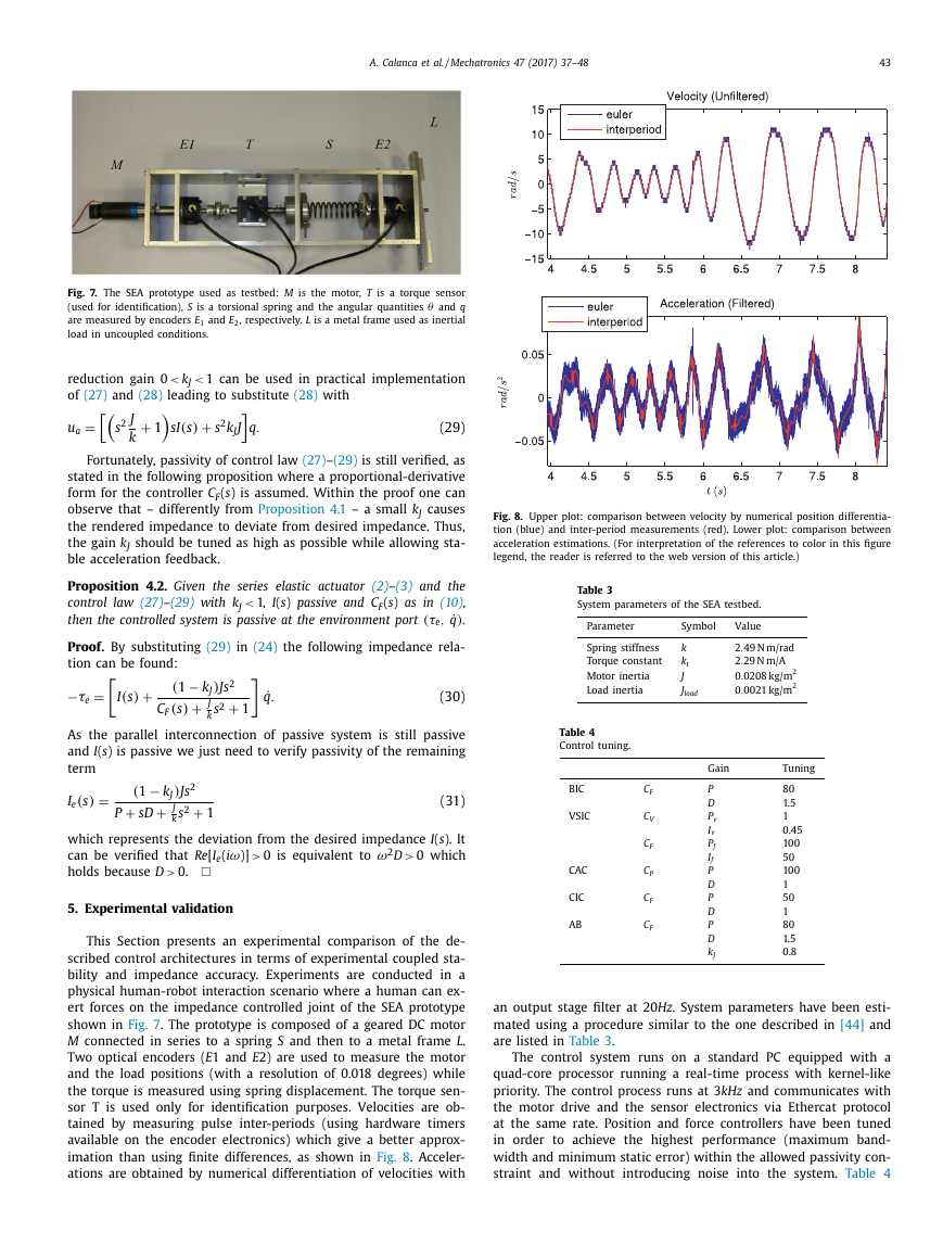
Fig. 7. The SEA prototype used as testbed: M is the motor, T is a torque sensor
θ and q
(used for identification), S is a torsional spring and the angular quantities
are measured by encoders E 1 and E 2 , respectively. L is a metal frame used as inertial
load in uncoupled conditions.
reduction gain 0
of (27) and (28) leading to substitute (28) with
k J
1 can be used in practical implementation
<
<
=
u a
2
s
+
J
1
k
sI(s
)
+
2 k J J
s
q.
(29)
Fortunately, passivity of control law (27) –(29) is still verified, as
stated in the following proposition where a proportional-derivative
form for the controller C F ( s ) is assumed. Within the proof one can
observe that – differently from Proposition 4.1 – a small k J causes
the rendered impedance to deviate from desired impedance. Thus,
the gain k J should be tuned as high as possible while allowing sta-
ble acceleration feedback.
Fig. 8. Upper plot: comparison between velocity by numerical position differentia-
tion (blue) and inter-period measurements (red). Lower plot: comparison between
acceleration estimations. (For interpretation of the references to color in this figure
legend, the reader is referred to the web version of this article.)
Proposition 4.2. Given the series elastic actuator (2) –(3) and the
control law (27) –(29) with k J
1, I ( s ) passive and C F ( s ) as in (10) ,
.
then the controlled system is passive at the environment port
(τe
)
,
˙ q
<
Proof. By substituting (29) in (24) the following impedance rela-
tion can be found:
(1
(s
)
− k J
+
−τe
=
(30)
I(s
)
+
1
.
˙ q
)
2
Js
2 +
J
s
k
C F
As the parallel interconnection of passive system is still passive
and I ( s ) is passive we just need to verify passivity of the remaining
term
=
)
(31)
(s
)
I e
− k J
(1
+
+
sD
P
2
Js
2 +
J
s
k
1
which represents the deviation from the desired impedance I ( s ). It
can be verified that Re [ I e ( i
0 which
holds because D
0 is equivalent to
ω)]
>
2 D
>
0.
ω
>
5. Experimental validation
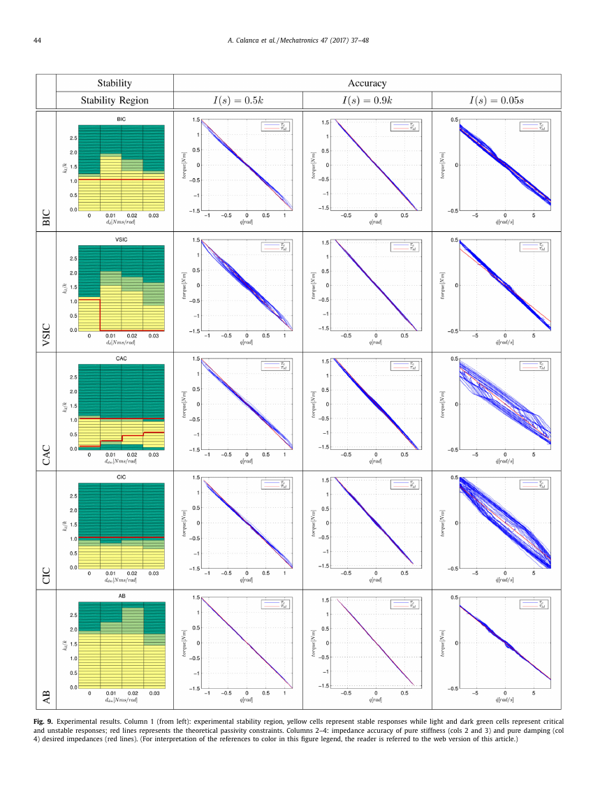
This Section presents an experimental comparison of the de-
scribed control architectures in terms of experimental coupled sta-
bility and impedance accuracy. Experiments are conducted in a
physical human-robot interaction scenario where a human can ex-
ert forces on the impedance controlled joint of the SEA prototype
shown in Fig. 7 . The prototype is composed of a geared DC motor
M connected in series to a spring S and then to a metal frame L .
Two optical encoders ( E 1 and E 2) are used to measure the motor
and the load positions (with a resolution of 0.018 degrees) while
the torque is measured using spring displacement. The torque sen-
sor T is used only for identification purposes. Velocities are ob-
tained by measuring pulse inter-periods (using hardware timers
available on the encoder electronics) which give a better approx-
imation than using finite differences, as shown in Fig. 8 . Acceler-
ations are obtained by numerical differentiation of velocities with
Table 3
System parameters of the SEA testbed.
Parameter
Symbol
Value
Spring stiffness
Torque constant
Motor inertia
Load inertia
k
k t
J
J load
.
49 N m/rad
2
.
29 N m/A
2
2
.
0208 kg/m
0
2
.
0
0021 kg/m
Table 4
Control tuning.
BIC
VSIC
CAC
CIC
AB
C F
C V
C F
C P
C F
C F
Gain
Tuning
P
D
P v
I v
P f
I f
P
D
P
D
P
D
k J
80
1.5
1
0.45
100
50
100
1
50
1
80
1.5
0.8
an output stage filter at 20 Hz . System parameters have been esti-
mated using a procedure similar to the one described in [44] and
are listed in Table 3 .
The control system runs on a standard PC equipped with a
quad-core processor running a real-time process with kernel-like
priority. The control process runs at 3 kHz and communicates with
the motor drive and the sensor electronics via Ethercat protocol
at the same rate. Position and force controllers have been tuned
in order to achieve the highest performance (maximum band-
width and minimum static error) within the allowed passivity con-
straint and without introducing noise into the system. Table 4
�
44
A. Calanca et al. / Mechatronics 47 (2017) 37–48
Fig. 9. Experimental results. Column 1 (from left): experimental stability region, yellow cells represent stable responses while light and dark green cells represent critical
and unstable responses; red lines represents the theoretical passivity constraints. Columns 2–4: impedance accuracy of pure stiffness (cols 2 and 3) and pure damping (col
4) desired impedances (red lines). (For interpretation of the references to color in this figure legend, the reader is referred to the web version of this article.)
�




 2023年江西萍乡中考道德与法治真题及答案.doc
 2012年重庆南川中考生物真题及答案.doc
 2013年江西师范大学地理学综合及文艺理论基础考研真题.doc
 2020年四川甘孜小升初语文真题及答案I卷.doc
 2020年注册岩土工程师专业基础考试真题及答案.doc
 2023-2024学年福建省厦门市九年级上学期数学月考试题及答案.doc
 2021-2022学年辽宁省沈阳市大东区九年级上学期语文期末试题及答案.doc
 2022-2023学年北京东城区初三第一学期物理期末试卷及答案.doc
 2018上半年江西教师资格初中地理学科知识与教学能力真题及答案.doc
 2012年河北国家公务员申论考试真题及答案-省级.doc
 2020-2021学年江苏省扬州市江都区邵樊片九年级上学期数学第一次质量检测试题及答案.doc
 2022下半年黑龙江教师资格证中学综合素质真题及答案.doc