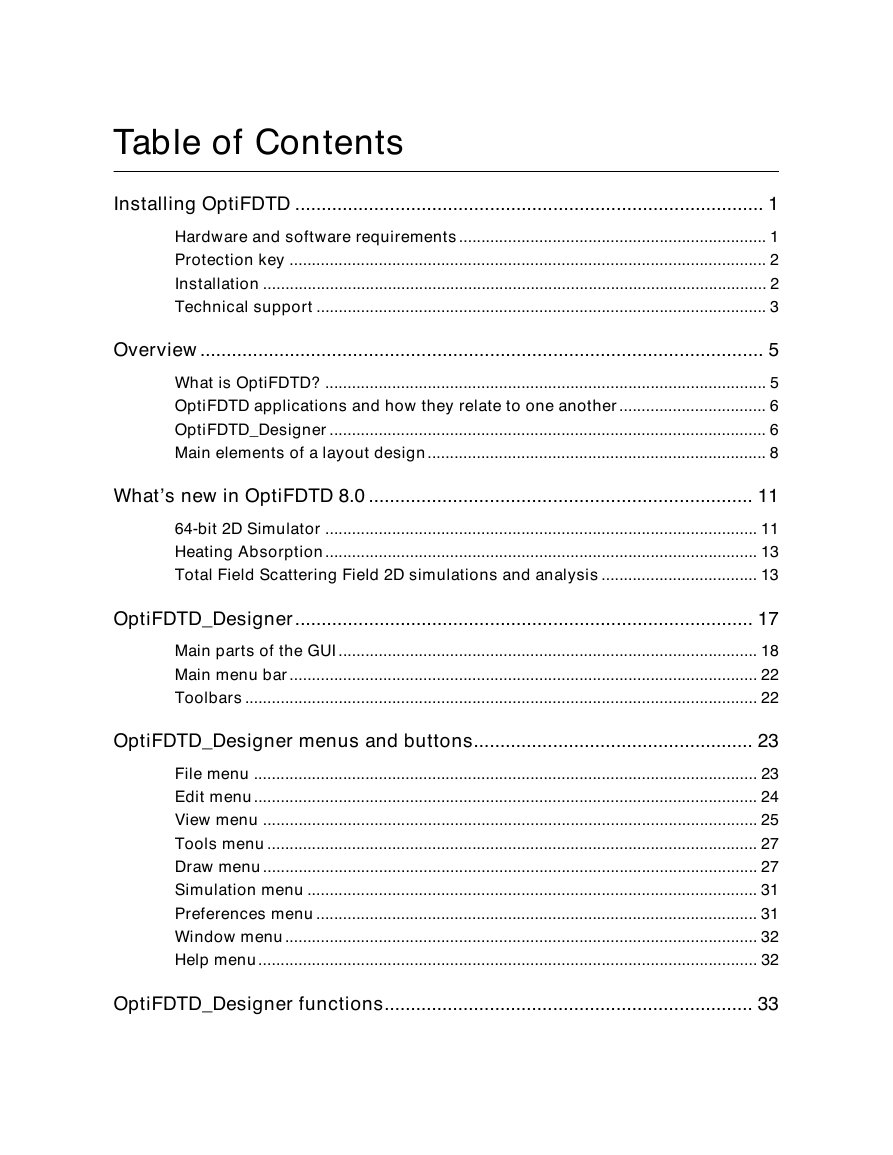
Installing OptiFDTD
Hardware and software requirements
Protection key
Installation
Installing OptiFDTD
Technical support
Overview
What is OptiFDTD?
OptiFDTD applications and how they relate to one another
OptiFDTD_Designer
Main elements of a layout design
Wafer
Waveguides
Input Field
Observation points, areas, and lines
What’s new in OptiFDTD 8.0
64-bit 2D Simulator
Notes on 64-bit Simulators
Heating Absorption
Total Field Scattering Field 2D simulations and analysis
OptiFDTD_Designer
Main parts of the GUI
Layout window
2D Ref. Index window
3D Ref. Index window
Scripting window
Notes window
Output window
Main menu bar
Toolbars
OptiFDTD_Designer menus and buttons
File menu
Edit menu
View menu
Tools menu
Draw menu
Simulation menu
Preferences menu
Window menu
Help menu
OptiFDTD_Designer functions
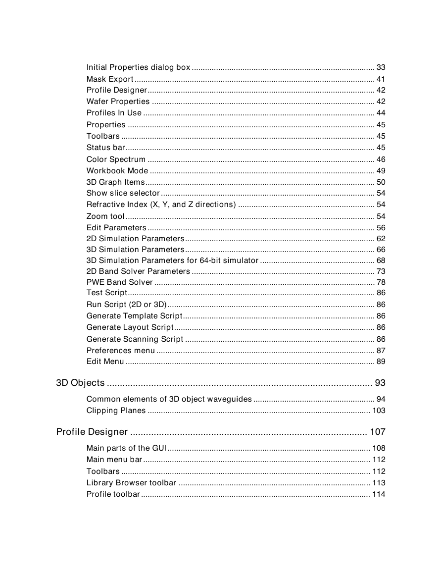
Initial Properties dialog box
Waveguide Properties tab
Wafer Dimensions tab
2D Wafer Properties tab
3D Wafer Properties tab
Profiles And Materials
Mask Export
Conversion Accuracy
Profile Designer
Wafer Properties
Wafer Properties dialog box
2D Wafer Properties tab
3D Wafer Properties tab
Profiles In Use
Properties
Toolbars
Status bar
Color Spectrum
Workbook Mode
3D Graph Items
Palette
Axis
Height Plot
Image Map
Plane View (X)
Plane View (Y)
Show slice selector
Refractive Index (X, Y, and Z directions)
Zoom tool
Edit Parameters
User Variable tab
User Function tab
DLL Function tab
2D Simulation Parameters
Mesh Parameters
Estimate minimal memory usage for dielectric materials
Boundary Conditions
Time Parameters
Key Input Information
Run button
Summary button
3D Simulation Parameters
Mesh Parameters
Estimate minimal memory usage for dielectric materials
Time Parameters
Key Input Information
Run button
Summary button
DFT Options
3D Simulation Parameters for 64-bit simulator
Mesh Parameters
Estimate minimal memory usage for dielectric materials
Time Parameters
Key Input Information
Time Sampling Interval
Run button
Summary button
DFT Options
Spectrum button
Spectral DFT Simulation Parameters
Spectral DFT parameters - automatic
Spectral DFT parameters – user defined
2D Band Solver Parameters
PWE Band Solver
Layout Designer
PWE Band Solver Simulator
PWE Band Solver Parameters dialog box
PWE Data Export dialog box
Advanced options dialog box
Test Script
Run Script (2D or 3D)
Generate Template Script
Generate Layout Script
Generate Scanning Script
Preferences menu
Layout Options
Grid
Edit Menu
Move group
3D Objects
Common elements of 3D object waveguides
Sphere waveguide
Ellipsoid waveguide
Block waveguide
Cylinder waveguide
Clipping Planes
Profile Designer
Main parts of the GUI
Library Browser
Layout
Output
Main menu bar
Toolbars
Library Browser toolbar
Profile toolbar
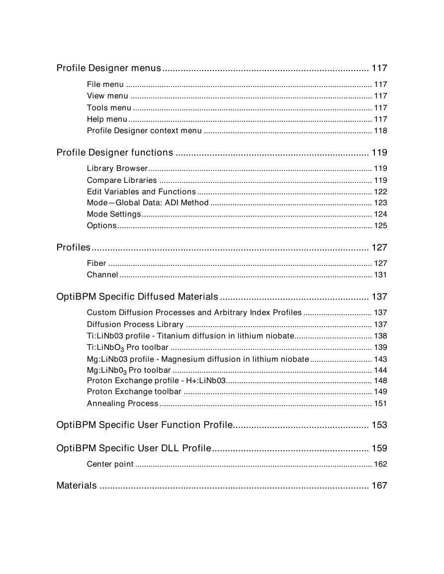
Profile Designer menus
File menu
View menu
Tools menu
Help menu
Profile Designer context menu
Profile Designer functions
Library Browser
Compare Libraries
Edit Variables and Functions
Mode—Global Data: ADI Method
Mode Settings
Options
Profiles
Fiber
Relative semi-axes
Refractive Index
Fiber Pro toolbar
Profile name
2D Profile Definition
3D profile definition
Slanted Walls
Channel
ChannelPro toolbar
Profile name
2D Profile Definition
3D profile definition
Slanted Walls
OptiBPM Specific Diffused Materials
Custom Diffusion Processes and Arbitrary Index Profiles
Diffusion Process Library
Ti:LiNb03 profile � Titanium diffusion in lithium niobate
Ti:LiNbO3 Pro toolbar
Profile name
Set default
Stripe thickness before diffusion
Group I
Group II
Dopant constant
Dispersion factor
Distribution constant
Distribution power factor
Mg:LiNb03 profile � Magnesium diffusion in lithium niobate
Mg:LiNb03 Pro toolbar
Profile name
Set default
Stripe thickness before diffusion
Group I
Group II
Dopant constant
Dispersion factor
Distribution constant
Distribution power factor
Proton Exchange profile - H+:LiNb03
Proton Exchange toolbar
Profile name
Annealing process
Diffusion depth before annealing
Proton source
Process parameters
Exchange
Maximum refractive index change on the surface
Annealing Process
OptiBPM Specific User Function Profile
Profile name
Profile function tab
User variables tab
User functions/DLLs tab
System constants tab
Material constants tab
OptiBPM Specific User DLL Profile
Profile name
Center point
Materials
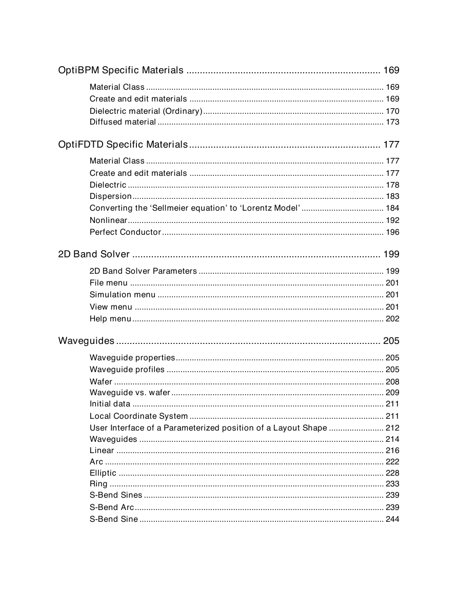
OptiBPM Specific Materials
Material Class
Create and edit materials
Dielectric material (Ordinary)
2D Isotropic tab
3D Isotropic tab
3D Anisotropic tab
Diffused material
Crystal Name
Default
Refractive Index
Electrooptic coefficients
Permittivities
Wavelength
Crystal Cut
Propagation direction (2D)
Polarization
OptiFDTD Specific Materials
Material Class
Create and edit materials
Dielectric
Constant Refractive Index
Sellmeier
Sellmeier equation
Dispersion
Lorentz Dispersion
Lorentz Model
Converting the ‘Sellmeier equation’ to ‘Lorentz Model’
Lorentz equation
Sellmeier equation
Relation between the two models
Drude Dispersion
Lorentz-Drude Dispersion
Refractive Index (RI) Viewer
Nonlinear
2nd Order
3rd Order
Kerr
Raman
Perfect Conductor
Materials in use
Backward compatibility
2D Band Solver
2D Band Solver Parameters
OptiFDTD_BandSolver
File menu
Simulation menu
View menu
Help menu
Waveguides
Waveguide properties
Waveguide profiles
Wafer
Waveguide vs. wafer
Waveguide width and wafer width
Depth description
Initial data
Local Coordinate System
User Interface of a Parameterized position of a Layout Shape
Waveguides
Linear
Linear waveguide path line
Linear Waveguide Properties dialog box
Start tab
End tab
Arc
Arc Waveguide Properties dialog box
Start tab
End tab
Elliptic
Elliptic Waveguide Properties dialog box
Center tab
Ring
Ring Waveguide Properties dialog box
Center tab
S-Bend Sines
S-Bend Arc
S-Bend Arc Properties dialog box
Start tab
End tab
S-Bend Sine
S-Bend Sine waveguide path line
S-Bend Sine Properties dialog box
Start tab
End tab
S-Bend Cosine
S-Bend Cosine Waveguide path line
S-Bend Cosine Properties dialog box
Start tab
End tab
Linear Taper
Linear Taper Waveguide Properties dialog box
Start tab
End tab
Parabolic Taper
Parabolic Taper Waveguide Properties dialog box
Start tab
End tab
Exponential Taper
Exponential Taper Waveguide path line
Formula for exponential profile
Exponential Taper Waveguide Properties dialog box
Start tab
End tab
S-Bend Arc Taper
S-Bend Arc Taper Properties dialog box
Start tab
End tab
S-Bend Sine Taper
S-Bend Sine Taper Waveguide path line
S-Bend Sine Taper Properties dialog box
Start tab
End tab
S-Bend Cosine Taper
S-Bend Cosine Taper Properties dialog box
Start tab
End tab
Circular Lens
Circular Lens Properties dialog box
Center tab
Elliptic Lens
Elliptic Lens Properties dialog box
Center tab
Parabolic Lens
Parabolic Lens Properties dialog box
Start tab
End tab
Hyperbolic Lens
Hyperbolic Lens Properties dialog box
Start tab
End tab
Polynomial
Polynomial waveguide path line
Polynomial Waveguide Properties dialog box
Start tab
End tab
Photonic Band Gap (PBG) Crystal Structure
Origin tab
Lattice Properties
Atom Waveguides in Unit Cell
Edit Options
Edit Basis Cell dialog box
Basic 3D Linear Tapering and Proportional Interpretation of Fiber Profile
Channel Profiles
Fiber Profiles
Input Field
Input Field vs. Input Plane
Insert an input plane
Input Field dialog box
General tab
2D Transverse tab
3D Transverse tab
Mode—Global Data: ADI Method
General tab
Settings tab
Wafer Data tab
Waveguide tab
Waveguides tab
Gaussian Modulated CW tab
Mode Solver 2D
Mode Solver 2D—menus
File menu
Tools menu
Confinement Factor
Overlap Integral Scanner
Overlap Integral
Gaussian Overlap Integral Scanner
Multiple Fields
Mode Solver 2D—tabs
Waveguides tab
Parameters tab
Modes tab
Graph Setting tab
Refractive index
TFSF Region Properties
General Input Field configuration
TF/SF Input Wave tab
2D SF Detectors tab
3D Mode Solver
Main parts of the GUI
Layout
Mode Found
Output
Main menu bar
Toolbars
3D Mode Solver menus and buttons
File menu
View menu
Simulation menu
Data menu
Preferences menu
Help menu
3D Mode Solver functions
Mode Found
Status Bar
3D Graph Items
Palette
Axis
Height Plot
Image Map
Plane View (XZ)
Plane View (YZ)
Show slice selector
Customize
Toolbars tab
Commands tab
Data menu
Save Refractive Index(es)
Save Modal Indexes
Save Mode(s)
3D Graph Settings
Region Of Interest
Height Plot Settings
Axis Settings
Image Map Settings
Palette Settings
Data Clamping
Layout Options
Grid
Observation Points, Areas, and Lines
Observation Point
Observation Area
Observation Line
Simulation toolbar
Observation Points
Observation properties—Point dialog box
General tab
Data Components tab
Observation Area
Observation properties����X�Z Area dialog box
General tab
Data Components tab
Observation properties����Y�Z Area dialog box
General tab
Data Components tab
Observation properties����X�Y Area dialog box
General tab
Data Components tab
Observation Area Analysis dialog box
Observation Point tab
Observation Line tab
Power Spectrum
Observation Area tab
Observation Area—2D simulations
Observation Area—3D simulations
Spectrum Analysis
Observation Line
Observation properties����Vertical Line dialog box
General tab
Data Components tab
OptiFDTD_Simulator (2D)
Main parts of the GUI
Graph window
Output window
Main menu bar
Toolbars
OptiFDTD_Simulator (2D) menus and buttons
File menu
View menu
Simulation menu
Preferences menu
Help menu
Simulation Parameters
Boundary Conditions
Observation Point
Finalization
OptiFDTD_Simulator (2D) functions
View list
Status bar
3D Graph Items
Palette
Axis
Height Plot
Image Map
Plane View (XZ)
Plane View (YZ)
3D Graph settings
Region of Interest
Height Plot Settings
Axis Settings
Image Map Settings
Palette Settings
Data Clamping
Show slice selector
OptiFDTD_Simulator (3D)
Main parts of the GUI
Graph window
Output window
Slicer
Main menu bar
Toolbars
OptiFDTD_Simulator (3D) menus and buttons
File menu
View menu
Simulation menu
Preferences menu
Help menu
Simulation Parameters
Boundary Conditions
Observation Point
Finalization
OptiFDTD_Simulator (3D) functions
View list
Status bar
3D Graph Items
Palette
Axis
Height Plot
Image Map
Plane View (XZ)
Plane View (YZ)
3D Graph settings
Region of Interest
Height Plot Settings
Axis Settings
Image Map Settings
Palette Settings
Data Clamping
Show slice selector
PWE Band Solver
PWE Band Solver dialog box
PWE Band Solver menus
OptiFDTD_Analyzer (2D�Simulations)
Main parts of the GUI
Layout
Ref. Index
Components
Poynting Vector
Output
Main menu bar
Toolbars
OptiFDTD_Analyzer menus and buttons (2D�Simulations)
File menu
View menu
Components menu
Simulation menu
Preferences menu
Tools menu
Window menu
Help menu
OptiFDTD_Analyzer functions (2D�Simulations)
Export
Export Data dialog box
3D Graph Items
Components menu
Components
Simulation menu
Simulation Parameters
Preferences menu
Tools menu
Observation Area Analysis
Crosscut viewer
Direction of the Crosscut
OptiFDTD_Analyzer (3D Simulations)
Main parts of the GUI
Layout
Ref. Index
Components (Ex, Ey, Ez, Hx, Hy, Hz)
Poynting Vector
Overlap Scan
Far Field
Slice chooser
Main menu bar
Toolbars
OptiFDTD_Analyzer menus and buttons (3D�simulations)
File menu
View menu
Components menu
Simulation menu
Preferences menu
Tools menu
Window menu
Help menu
OptiFDTD_Analyzer functions (3D simulations)
Analysis Tools
Mode Overlap Integral (MOI)
Input Overlap Integral (IOI)
Input Overlap Integral Scanner (IOIS)
Far Field
Power
Export
Export Data dialog box
3D Graph Items
Simulation menu
Simulation Parameters
Components menu
Components
Preferences menu
OptiFDTD Tools
Overlap Integral
Gaussian Overlap Scanner
Overlap Integral Scanner
Multiple Fields
Notes
Multiple Gaussians
Notes
Confinement Factor
Notes
Far Field
Fraunhofer approximation
Fresnel-Kirchhoff Diffraction Formula
2D Far Field
3D Far Field
References
Mode 2D
Modes of Planar Waveguides
File menu
Edit menu
View menu
Simulation menu
Window menu
Simulation functions
Correlation Function Method (CFM)
File menu
Edit menu
View menu
Simulation menu
Window menu
Simulation functions
User Defined File
File menu
Edit menu
View menu
Simulation menu
Window menu
Notes:
Mode 3D
File menu
Edit menu
View menu
Operations menu
Simulation menu
Draw Tool menu
Preferences menu
Layout Designer Dialog boxes of Mode Solver 3D
Layout Settings layout dialog box
Waveguide Colors layout dialog box
Notes:
User Guide of View 3D
Commands of View 3D
View menu
Toolbars menu
Status Bar menu
Settings menu
Dialog boxes of View 3D
Notes:
Code V Converter
Data format
EXFO OWA Converter
Zemax Converter
Conversion
Notes on Conversion
Data formats
ZEMAX Beam File (ZBF) binary format
Appendix A: Opti2D Graph Control
User interface features
Information windows
Info-window
Legend
Graph toolbox
Graph tools
Graph Menu
Tools
Windows
Printing and exporting files
Utilities
Help
Import Curve
Displays
Graph Properties dialog
X-Axis
Y-Axis
Curve
Curve properties
Grid
Fonts
Legend
Graph
Label Management tab
Appendix B: File formats
Data file formats
Real Data 2D File Format: BCF2DPC
Real Data 3D File Format: BCF3DPC
Complex Data 2D File Format: BCF2DCX
Complex Data 3D File Format: BCF3DCX
User Refractive Index Distribution File Format
Example
Appendix C: Parser supported functions
Supported functions
Mathematical constants
Physical constants
Function Limits and _FnRslt_
Examples
Operators and their precedence
Appendix D: Batch processing
Batch processing file format
Automatic loading of VB Script from command line
Command line syntax
Batch command examples



 2023年江西萍乡中考道德与法治真题及答案.doc
 2012年重庆南川中考生物真题及答案.doc
 2013年江西师范大学地理学综合及文艺理论基础考研真题.doc
 2020年四川甘孜小升初语文真题及答案I卷.doc
 2020年注册岩土工程师专业基础考试真题及答案.doc
 2023-2024学年福建省厦门市九年级上学期数学月考试题及答案.doc
 2021-2022学年辽宁省沈阳市大东区九年级上学期语文期末试题及答案.doc
 2022-2023学年北京东城区初三第一学期物理期末试卷及答案.doc
 2018上半年江西教师资格初中地理学科知识与教学能力真题及答案.doc
 2012年河北国家公务员申论考试真题及答案-省级.doc
 2020-2021学年江苏省扬州市江都区邵樊片九年级上学期数学第一次质量检测试题及答案.doc
 2022下半年黑龙江教师资格证中学综合素质真题及答案.doc