ASR Microelectronics Confidential
密级状态:绝密( ) 秘密( √ ) 内部资料() 公开(√)
文档编号: (芯片型号) –ASR6505(英文、数字)
ASR6505 Datasheet
文件状态:
当前版本:
V0.3
[√] 正在修改
作者:
ASR6505 Design Team
[ ] 正式发布
启动日期:
2019-3-1
审核:
完成日期:
2019-7-1
翱捷科技(深圳)有限公司
ASR Microelectronics Co., Ltd
(版本所有,翻版必究)
1 / 10
�
ASR Microelectronics Confidential
版本历史
版本号 修改日期
作 者
修 改 说 明
V0.1
2019.3.12
ASR6505 Design Team Created
V0.2
2019.5.24
ASR6505 Design Team 1. Change the pinmap description.
2. Change chip current parameters.
V0.3
2019.7.1
ASR6505 Design Team 1. Change Product marking of ASR6505.
2 / 10
�
ASR Microelectronics Confidential
Table of Contents
1 GENERAL DESCRIPTION ...................................................................................................................................... 4
1.1
1.2
1.3
Key Feature .............................................................................................................................................. 4
Block Diagram .......................................................................................................................................... 5
General Specification ............................................................................................................................... 5
2
ELECTRICAL CHARACTERISTICS .................................................................................................................... 5
2.1
2.2
2.3
2.4
2.5
Absolute Maximum Rating ...................................................................................................................... 5
Power Consumption Characteristics ........................................................................................................ 6
Recommended Operating Range ............................................................................................................. 6
RF Characteristics ..................................................................................................................................... 6
Digital Characteristics .............................................................................................................................. 7
DC Characteristics ........................................................................................................................ 7
RST Characteristics ....................................................................................................................... 7
2.5.1
2.5.2
3
PIN DEFINITION ...................................................................................................................................................... 7
3.1
Pin Assignment ........................................................................................................................................ 9
4 MECHANICAL DIMENSION .............................................................................................................................. 10
5
PACKAGE INFORMATION .................................................................................................................................. 10
5.1
Product Marking .................................................................................................................................... 10
3 / 10
�
ASR Microelectronics Confidential
1 General Description
The ASR6505 is a general LoRa Wireless Communication Chipset, with integrated LoRa Radio Transceiver,
LoRa Modem and an 8-Bit CISC MCU. The MCU uses an advanced STM 8-bit core, with 16MHz operation frequency.
The LoRa Radio Transceiver has continuous frequency coverage from 150MHz to 960MHz. The LoRa Modem
supports LoRa modulation for LPWAN use cases and (G)FSK modulation for legacy use cases. The LoRa Wireless
Communication module designed by ASR6505 provides ultra long range and ultra low power communication for
LPWAN application.
The ASR6505 can achieve a high sensitivity of over -140dBm and the maximum transmit power is higher than
+21dBm. This makes it suitable to be used in long range LPWAN and have high efficiency. The total chip package is
of very small size, 8mm x 8mm, with totally 68 pins.
1.1 Key Feature
SX1262+STM8L152 integrated.
Small footprint: 8mm x 8mm x 0.9mm, QFN 68pin.
LoRa Radio and LoRa Modem.
Frequency Range: 150MHz ~ 960MHz.
Maximum Power +21dBm constant RF output.
High sensitivity: down to -140dBm.
Deepsleep mode current with RTC: 2uA.
TX mode current @17dBm: 50mA, @14dBm: 40mA.
RX mode current: 10mA.
Programmable bit rate up to 62.5kbps in LoRa modulation mode.
Programmable bit rate up to 300kbps in (G)FSK modulation mode.
Preamble detection.
Embedded memories (up to 64k bytes of Flash memory and 4k bytes of SRAM, 2k bytes of EEPROM).
30x configurable GPIOs, 1xI2C, 2xUART, 1xSWIM, 1xSPI, 3xADC.
LCD driver: 2/4/8 COM, Max 24 Segments.
16-MHz Harvard architecture CPU.
4-Channel DMA engine.
Embedded 12-bit 1Msps SAR ADC.
Embedded 2x12-bit DAC.
Embedded 2x low power comparators.
96-bit unique Chip ID.
32.768kHz External Watch Crystal Oscillator.
1-16MHz External Crystal Oscillator for MCU (Optional).
32MHz External Crystal Oscillator for LoRa Radio.
Embedded internal Low frequency (38kHz) RC oscillator.
Most complete EVK demo, with LCD, sensors, debug interfaces on board.
4 / 10
�
ASR Microelectronics Confidential
1.2 Block Diagram
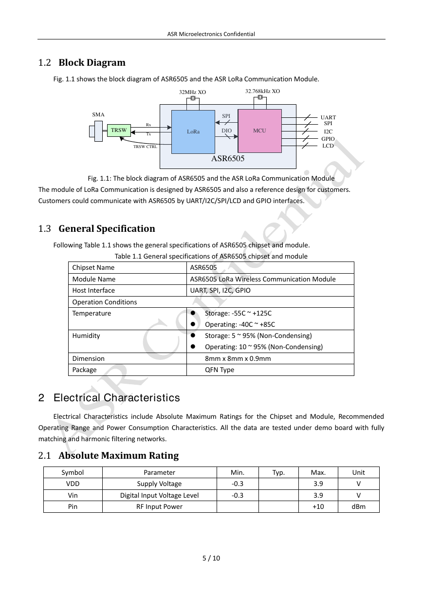
Fig. 1.1 shows the block diagram of ASR6505 and the ASR LoRa Communication Module.
Fig. 1.1: The block diagram of ASR6505 and the ASR LoRa Communication Module
The module of LoRa Communication is designed by ASR6505 and also a reference design for customers.
Customers could communicate with ASR6505 by UART/I2C/SPI/LCD and GPIO interfaces.
1.3 General Specification
Following Table 1.1 shows the general specifications of ASR6505 chipset and module.
Table 1.1 General specifications of ASR6505 chipset and module
Chipset Name
Module Name
Host Interface
Operation Conditions
Temperature
Humidity
Dimension
Package
ASR6505
ASR6505 LoRa Wireless Communication Module
UART, SPI, I2C, GPIO
Storage: -55C ~ +125C
Operating: -40C ~ +85C
Operating: 10 ~ 95% (Non-Condensing)
Storage: 5 ~ 95% (Non-Condensing)
8mm x 8mm x 0.9mm
QFN Type
2 Electrical Characteristics
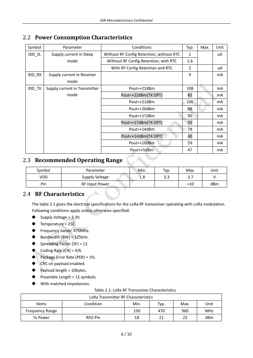
Electrical Characteristics include Absolute Maximum Ratings for the Chipset and Module, Recommended
Operating Range and Power Consumption Characteristics. All the data are tested under demo board with fully
matching and harmonic filtering networks.
2.1 Absolute Maximum Rating
Symbol
VDD
Vin
Pin
Parameter
Supply Voltage
Digital Input Voltage Level
RF Input Power
Min.
-0.3
-0.3
Typ.
Max.
3.9
3.9
+10
Unit
V
V
dBm
5 / 10
LoRaMCU32.768kHz XO32MHz XOTRSWSPIDIOSMATRSW CTRLRxTxASR6505UARTI2CSPIGPIOLCD�
ASR Microelectronics Confidential
2.2 Power Consumption Characteristics
Symbol
IDD_SL
Parameter
Conditions
Typ. Max. Unit
Supply current in Sleep
Without RF Config Retention, without RTC
mode
Without RF Config Retention, with RTC
With RF Config Retention and RTC
IDD_RX
Supply current in Receiver
mode
IDD_TX
Supply current in Transmitter
Pout=+22dBm
mode
Pout=+22dBm(TX OPT)
Pout=+21dBm
Pout=+20dBm
Pout=+17dBm
Pout=+17dBm(TX OPT)
Pout=+14dBm
Pout=+14dBm(TX OPT)
Pout=+10dBm
Pout=+5dBm
1
1.6
2
9
108
85
106
98
90
50
78
40
59
47
uA
uA
mA
mA
mA
mA
mA
mA
mA
mA
mA
mA
mA
2.3 Recommended Operating Range
Symbol
VDD
Pin
Parameter
Supply Voltage
RF Input Power
Min.
1.8
Typ.
3.3
Max.
3.7
+10
Unit
V
dBm
2.4 RF Characteristics
The table 2.1 gives the electrical specifications for the LoRa RF transceiver operating with LoRa modulation.
Following conditions apply unless otherwise specified:
Supply Voltage = 3.3V.
Temperature = 25C.
Frequency bands: 470MHz.
Bandwidth (BW) = 125kHz.
Spreading Factor (SF) = 12.
Coding Rate (CR) = 4/6.
Package Error Rate (PER) = 1%.
CRC on payload enabled.
Payload length = 10bytes.
Preamble Length = 12 symbols.
With matched impedances.
Table 2.1: LoRa RF Transceiver Characteristics
LoRa Transmitter RF Characteristics
Items
Frequency Range
Tx Power
Condition
RFO Pin
Min.
150
18
Typ.
470
21
Max.
960
22
Unit
MHz
dBm
6 / 10
�
ASR Microelectronics Confidential
LoRa Receiver RF Characteristics
Items
Frequency Range
Condition
Sensitivity
125kHz Bandwidth, SF=7
125kHz Bandwidth, SF=10
125kHz Bandwidth, SF=12
2nd order harmonic
Tx Power = 20dBm
2.5 Digital Characteristics
2.5.1 DC Characteristics
Min.
150
Typ.
470
-126
-135
-140
-41
Max.
960
Unit
MHz
dBm
dBm
dBm
dBm
Symbol
Description
Conditions
Min.
Typ.
Max.
Unit
VIH
VIL
RPU
RPD
I/O input high level
I/O input low level
Weak pull up resistor
Vin=GND
Weak pull down resistor
Vin=VDD
0.7xVDD
30
30
45
45
0.3xVDD
60
60
V
V
KΩ
KΩ
2.5.2 RST Characteristics
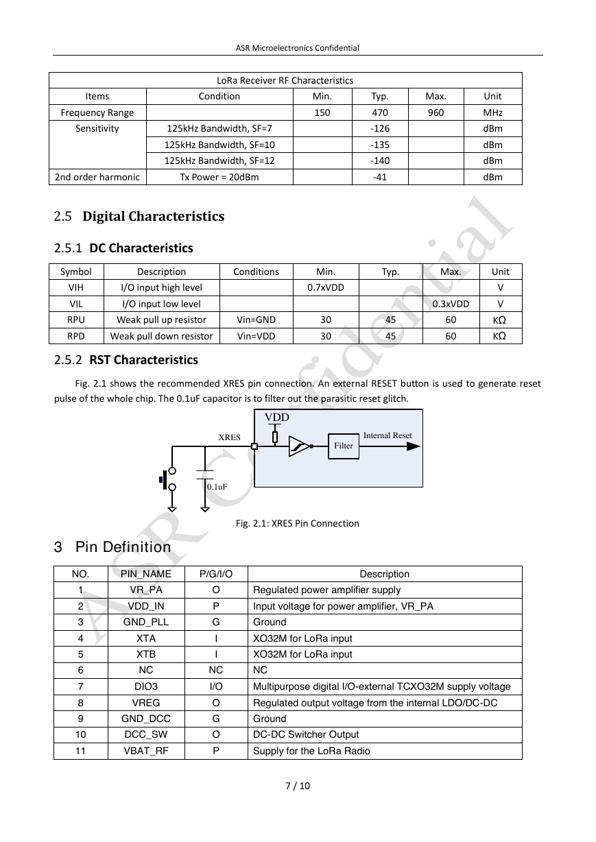
Fig. 2.1 shows the recommended XRES pin connection. An external RESET button is used to generate reset
pulse of the whole chip. The 0.1uF capacitor is to filter out the parasitic reset glitch.
Fig. 2.1: XRES Pin Connection
3 Pin Definition
NO.
PIN_NAME
P/G/I/O
Description
1
2
3
4
5
6
7
8
9
10
11
VR_PA
VDD_IN
GND_PLL
XTA
XTB
NC
DIO3
VREG
GND_DCC
DCC_SW
VBAT_RF
O
P
G
I
I
NC
I/O
O
G
O
P
Regulated power amplifier supply
Input voltage for power amplifier, VR_PA
Ground
XO32M for LoRa input
XO32M for LoRa input
NC
Multipurpose digital I/O-external TCXO32M supply voltage
Regulated output voltage from the internal LDO/DC-DC
Ground
DC-DC Switcher Output
Supply for the LoRa Radio
7 / 10
XRESVDDFilterInternal Reset0.1uF�
12
13
14
15
16
17
18
19
20
21
22
23
24
25
26
27
28
29
30
31
32
33
34
35
36
37
38
39
40
41
42
43
44
45
46
47
48
49
50
51
52
53
54
VBAT_DIO
DIO2
SWIM
NRST
LCD_COM0
LCD_COM1
LCD_COM2
VDDA
VREFP
UART1_RX
UART1_TX
VLCD
LCD_SEG0
LCD_SEG1
LCD_SEG2
LCD_SEG3
LCD_COM3
LCD_SEG4
LCD_SEG5
UART0_RX
UART0_TX
VDDD1
LCD_SEG6
LCD_SEG7
LCD_SEG8
LCD_SEG9
VDDD2
SPI_MISO
SPI_MOSI
SPI_SCK
SPI_NSS
LCD_SEG10
LCD_SEG11
LCD_SEG12
LCD_SEG13
LCD_SEG14
LCD_SEG15
LCD_SEG16
GPIO1
GPIO0
LCD_SEG17
I2C_SDA
I2C_SCL
P
I/O
I/O
I/O
I/O
I/O
I/O
P
I
I/O
I/O
I
I/O
I/O
I/O
I/O
I/O
I/O
I/O
I
I
P
I/O
I/O
I/O
I/O
P
I
I
I
I
I/O
I/O
I/O
I/O
I/O
I/O
I/O
I/O
I/O
I/O
I/O
I/O
ASR Microelectronics Confidential
Digital I/O supply voltage
Multipurpose digital I/O-RF switch control
SWIM download pin
External reset pin
LCD Common pin 0
LCD Common pin 1
LCD Common pin 2
Power supply for MCU analog section
VREFP for ADC
UART1 RX pin, wake up UART.
UART1 TX pin, wake up UART.
VLCD voltage input
LCD Segment pin 0
LCD Segment pin 1
LCD Segment pin 2
LCD Segment pin 3
LCD Common pin 3
LCD Segment pin 4
LCD Segment pin 5
UART0 RX pin, wake up UART.
UART0 TX pin, wake up UART.
Power supply for MCU digital section
LCD Segment pin 6
LCD Segment pin 7
LCD Segment pin 8
LCD Segment pin 9
Power supply for MCU digital section
SPI slave output, can be external SPI
SPI slave input, can be external SPI
SPI clock, can be external SPI
SPI slave select, can be external SPI
LCD Segment pin 10
LCD Segment pin 11
LCD Segment pin 12
LCD Segment pin 13
LCD Segment pin 14
LCD Segment pin 15
LCD Segment pin 16
SPI2 NSS
MCU GPIO
LCD Segment pin 17
I2C SDA pin
I2C SCL pin
8 / 10
�


 2023年江西萍乡中考道德与法治真题及答案.doc
 2012年重庆南川中考生物真题及答案.doc
 2013年江西师范大学地理学综合及文艺理论基础考研真题.doc
 2020年四川甘孜小升初语文真题及答案I卷.doc
 2020年注册岩土工程师专业基础考试真题及答案.doc
 2023-2024学年福建省厦门市九年级上学期数学月考试题及答案.doc
 2021-2022学年辽宁省沈阳市大东区九年级上学期语文期末试题及答案.doc
 2022-2023学年北京东城区初三第一学期物理期末试卷及答案.doc
 2018上半年江西教师资格初中地理学科知识与教学能力真题及答案.doc
 2012年河北国家公务员申论考试真题及答案-省级.doc
 2020-2021学年江苏省扬州市江都区邵樊片九年级上学期数学第一次质量检测试题及答案.doc
 2022下半年黑龙江教师资格证中学综合素质真题及答案.doc