SEMI E4-0699
SEMI EQUIPMENT COMMUNICATIONS STANDARD 1 MESSAGE
TRANSFER (SECS-I)
This standard was technically approved by the Global Information & Control Committee and is the direct
responsibility of the North American Information & Control Committee. Current edition approved by the
North American Regional Standards Committee on February 28, 1999. Initially available at www.semi.org
May 1999; to be published June 1999. Originally published in 1980; previously published January 1999.
1 Introduction
1.1 Revision History — This is the first major revision
since the original release of SECS-I in 1980. Very little
of the original intent of SECS-I has been altered,
although there are a few significant additions. The
changes are summarized
in Appendix 1. This
specification has been developed in cooperation with
the Japan Electronic Industry Development Association
Committee 12 on Equipment Communications.
1.2 Scope — The SECS-I standard defines a
communication interface suitable for the exchange of
messages between semiconductor processing equipment
and a host. Semiconductor processing equipment
includes equipment intended for wafer manufacturing,
wafer processing, process measuring, assembly and
packaging. A host is a computer or network of
computers which exchange
the
equipment to accomplish manufacturing. This standard
includes the description of the physical connector,
signal levels, data rate and logical protocols required to
exchange messages between the host and equipment
over a serial point-to-point data path. This standard
does not define the data contained within a message.
The meaning of messages must be determined through
some message content standard such as SEMI
Equipment Communications Standard E5 (SECS-II).
information with
1.3 Intent — This standard provid es a means for
independent manufacturers
to produce equipment
and/or hosts which can be connected without requiring
specific knowledge of each other.
1.3.1 Layered Protocol — The SEC S-I protocol can
be thought of as a layered protocol used for point-to-
point communication. The levels within SECS-I are the
physical link, block transfer protocol, and message
protocol. (See Related Information R1-1.1.)
1.3.2 Speed — It is not the intent of this standard to
meet
the communication needs of all possible
applications. For example, the speed of RS-232 may be
insufficient to meet the needs of transferring mass
amounts of data or programs in a short period of time,
such as might be required by high speed functional test
applications.
1.3.3 Network Support — The method by which
blocks of data are routed to a piece of equipment or find
their way back to the proper host application is not
specified by SECS-I. In a network, the roles of host and
equipment might be assumed by any party in the
network.
the
communications link must assume the role of the
equipment and the other the role of the host.
situation, one
end of
In
this
1.4 Applicable Documents
1.4.1 Electronics Industries Associa tion Standards1
EIA RS-232-C — Interface between Data Terminal
Equipment and Data Communication Equipment
Employing Serial Binary Data Interchange
EIA RS-269-B — Synchronous Signaling Rates for
Data Transmission
EIA RS-334 — Signal Quality at Interface Between
Data Processing Terminal Equipment and Synchronous
Communication
Serial Data
Transmission
Equipment
for
EIA RS-422 — Electrical Characteristics of Balanced
Voltage Digital Interface Circuits
EIA RS-423 — Electrical Characteristics of
Unbalanced Voltage Digital Interface Circuits
1.4.2 European Computer Manufacturing Association2
ECMA/TC24/82/18 — "Network Layer Principles,"
Final Draft (April, 1982)
1.4.3 Japanese Industrial Standards Committees3
JIS C 6361 — "The Interface between Data Circuit
Terminating Equipment (DCE) and Data Terminal
Equipment (DTE) (25-pin Interface)"
1.4.4 International Organization for Standardization4
1 EIA Engineering Department, Standards Sales Office, 2001 Eye
Street, N.W., Washington, D.C. 20006
2 European Computer Manufacturing Association, 114 Rue du Rhone,
1204 Geneva, Switzerland
3 Japanese Standards Association, 1-24, Akasaka 4 Chome, Minato-
ku, Tokyo 107, Japan
4 ANSI, 1430 Broadway, New York, NY 10018
1
SEMI E4-0699 © SEMI 1980, 1999
�
ISO 2110-1980 — Data Communications, Interface
Connectors and Pin Assignment
2.1.7 checksum — a 16-bit number u sed to detect
transmission errors. (See Section 5.7.)
1.4.5 SEMI Specifications
SEMI E5 — SEMI Equipment Communications
Standard 2 — Message Content (SECS-II)
SEMI E6 — SEMI Facilities Interface Specification
Format
1.5 Overview of SECS-I — The SE CS-I standard
defines point-to-point communication of data utilizing a
subset of the international standard known in the U.S.A.
as EIA RS-232-C and in Japan as JIS C 6361 for the
connector and voltage levels. The actual transmission
consists of 8-bit bytes sent serially with one start and
one stop bit. The communication is bidirectional and
asynchronous, but flows in one direction at a time. The
direction is established by special characters and a
handshake, after which the data itself is sent. Data is
sent in blocks of 254 bytes or less. Each block consists
of a 10-byte header followed by data. A message is a
complete unit of communication in one direction and
consists of 1 to 32,767 blocks. Each block header
contains information for identifying the block as part of
a specific message. Messages are paired by a request
and its reply which together are called a transaction.
1.6 Structure of Document — This document is
divided into sections which correspond to major aspects
of the standard. The sections outline requirements as
well as implications of the requirements. The standard
may be implemented in a variety of ways, depending
upon the computer environment where it is placed.
Implementation is not part of the standard. Information
which may be useful for implementation is included in
the form of Related Information.
2 Terminology
2.1 The following brief definitions refer to sections
providing further information.
2.1.8 communication failure — a failure in the
communication link resulting from a failed send. (See
Section 5.4.)
2.1.9 device ID — a 15-bit field in t he header used to
identify the equipment. (See Section 6.3.)
2.1.10 E-bit — a bit in the header ide ntifying the last
block of a message. (See Section 6.6.)
2.1.11 ENQ — "Request to Send" handshake code.
(See Section 5.2.)
2.1.12 EOT — "Ready to Receive" ha ndshake code.
(See Section 5.2.)
2.1.13 equipment — the intelligent sy stem which
communicates with a host.
2.1.14 expected block — the block of a message which
is expected by the message protocol. (See Section
7.4.4.)
2.1.15 header — a 10-byte data element used by the
message and transaction protocols. (See Section 6.)
2.1.16 host —
communicates with the equipment.
intelligent
the
system which
2.1.17 length byte — the character us ed to establish
the block length during transmission. (See Section 5.6.)
2.1.18 line control — a portion of the block transfer
protocol. (See Section 5.8.2.)
2.1.19 master — the block transfer de signation for the
equipment. (See Section 5.5.)
2.1.20 message — a complete unit of communication.
(See Section 7.)
2.1.21 message ID — a 15-bit field in the header used
in the process of message identification. (See Sections
6.5, 7.3.1.)
2.1.1 ACK — "Correct Reception" handshake code.
(See Section 5.2.)
2.1.22 multi-block message — a mess age sent in more
than one block. (See Sections 6.7, 7.2.2.)
2.1.2 application software — the so ftware performing
the specific task of the equipment or the host.
2.1.23 NAK — "lncorrect Reception" handshake code.
(See Section 5.2.)
2.1.3 block — header plus up to 244 bytes of data.
(See Sections 1.5, 6.7.)
2.1.4 block length — the number of bytes sent in the
block transfer protocol. (See Section 5.6.)
2.1.5 block number — a 15-bit field in the header for
numbering blocks in a message. (See Sections 6.7.)
2.1.6 character — a byte sent on the SECS-I serial
line. (See Section 4.1.)
2.1.24 open message — a multi-block message for
which not all of the blocks have been received. (See
Section 7.4.4.)
2.1.25 open transaction — a transaction in progress.
(See Section 7.3.)
2.1.26 primary message — a message with an odd
numbered message ID. Also the first message of a
transaction. (See Section 6.5.)
SEMI E4-0699 © SEMI 1980, 1999
2
�
2.1.27 primary/secondary attribute — the least signifi-
cant bit of the lower message ID which indicates
whether a block belongs to a primary or secondary
message.
2.1.28 R-bit — a bit in the header sig nifying the
direction of the message. (See Section 6.2.)
2.1.29 receiver — the end of the SEC S-I link
receiving a message. (See Section 5.8.4.)
2.1.30 reply — the particular secondary message
corresponding to a primary message. (See Section 7.3.)
2.1.31 reply linking — the process of forming a
transaction out of a primary and a secondary message.
(See Section 7.3.1.)
2.1.32 retry count — the number of u nsuccessful
attempts to send a block in the block transfer protocol.
(See Section 5.4.)
2.1.33 RTY — the retry limit or the nu mber of times
the block transfer protocol will attempt to retry sending
a block before declaring a failed send. (See Section
5.4.)
2.1.34 secondary message — a messa ge with an even
numbered message ID. Also the second message of a
transaction. (See Section 6.5.2.)
2.1.35 sender — the end of the SECS -I link sending
message. (See Section 5.8.3.)
2.1.36 slave — the block transfer desi gnation for the
host (See Section 5.5.)
2.1.37 system bytes — a 4-byte field in the header
used for message identification. (See Section 6.8.)
2.1.38 T1 — receive inter-character t imeout in the
block transfer protocol. (See Section 5.3.1.)
2.1.39 T2 — protocol timeout in the b lock transfer
protocol. (See Section 5.3.2.)
2.1.40 T3 — reply timeout in the mes sage protocol.
(See Sections 5, 7.3.2)
2.1.41 T4 — inter-block timeout in th e message
protocol. (See Section 7.4.3.)
2.1.42 transaction — a primary mess age and its
associated secondary message, if any. (See Section 7.3.)
2.1.43 W-bit — a bit in the header sig nifying that a
reply is expected. (See Section 6.4.)
3.2 Electrical Interface — The connection will include
a serial interface according to EIA Standard RS-232-C
for interface Type E, full duplex communication,
modified by the deletions, additions and exceptions
described in this section.
3.2.1 Connector — Either the 9-pin or 25-pin
connector described in the EIA RS232 may be used. In
the case of the 25-pin connector a female connector will
be mounted on the equipment and a male connector will
be mounted on the cable from the host. In the case of
the 9-pin connector the male connector will be mounted
on the equipment and a female connector will be
mounted on the cable. The connector on the equipment
will have female 4-40 threaded jack screw locks.
NOTE: Suitable 25-pin connectors known as Type "D" are
similar to Amphenol MIN RAC 17 series with jack screw
locks. Suitable 9-pin connector is also Type "D" with
jackscrew locks. It is the type commonly implemented on
desktop and notebook PCs.
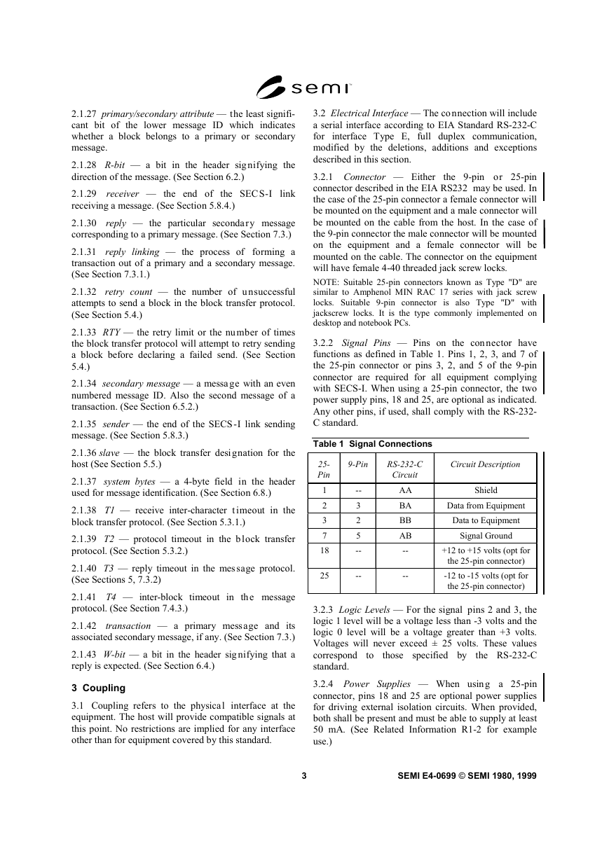
3.2.2 Signal Pins — Pins on the connector have
functions as defined in Table 1. Pins 1, 2, 3, and 7 of
the 25-pin connector or pins 3, 2, and 5 of the 9-pin
connector are required for all equipment complying
with SECS-I. When using a 25-pin connector, the two
power supply pins, 18 and 25, are optional as indicated.
Any other pins, if used, shall comply with the RS-232-
C standard.
Table 1 Signal Connections
25-
Pin
1
2
3
7
18
25
9-Pin
RS-232-C
Circuit
Circuit Description
--
3
2
5
--
--
AA
BA
BB
AB
--
--
Shield
Data from Equipment
Data to Equipment
Signal Ground
+12 to +15 volts (opt for
the 25-pin connector)
-12 to -15 volts (opt for
the 25-pin connector)
3.2.3 Logic Levels — For the signal pins 2 and 3, the
logic 1 level will be a voltage less than -3 volts and the
logic 0 level will be a voltage greater than +3 volts.
Voltages will never exceed ± 25 volts. These values
correspond
the RS-232-C
standard.
those specified by
to
3 Coupling
3.1 Coupling refers to the physical interface at the
equipment. The host will provide compatible signals at
this point. No restrictions are implied for any interface
other than for equipment covered by this standard.
3.2.4 Power Supplies — When using a 25-pin
connector, pins 18 and 25 are optional power supplies
for driving external isolation circuits. When provided,
both shall be present and must be able to supply at least
50 mA. (See Related Information R1-2 for example
use.)
3
SEMI E4-0699 © SEMI 1980, 1999
�
3.3 Data Rate — The supported data rates on signal
pins shall be 9600, 4800, 2400, 1200, and 300 baud.
The same data rate shall apply for data sent to and from
the equipment. The data rate shall be controlled to
better than 0.5%. (See RS-269-B and RS-334.) Optional
rates of 19,200 and 150 baud may be supplied if
desired.
3.4 Physical Medium — The connection with the host
may involve any medium that provides the required RS-
232-C quality, signal levels and data rate at the equip-
ment connector. The quality of signal should be such
that the effective bit error rate is less than 1 × 10⁻⁶. This
rate can be achieved easily with hardwired systems.
The distance limits specified in RS-232-C apply only to
systems using the wiring technique described in RS-
232-C. Since any method may be used in SECS-I as
long as RS-232-C signals are supplied at the connector,
the distance and isolation is dependent upon the design
of the physical medium which is external to the SECS-I
standard. (See Related Information R1-2.)
4 Character Structure
4.1 Characters — Data will be tra nsmitted or received
in a serial bit stream of 10 bits per character at one of
the specified data rates. The standard character has one
start bit (0), 8 data bits and one stop bit (1). All bit
transmissions are of the same duration. The 8 data bits
are numbered from 1 to 8 in the order sent (see Figure
1). The timing between characters is asynchronous with
respect to the data rate. The 8 data bits may be any
arbitrary code. The eight data bits will hereafter be
referred to as a byte.
Figure 1
Character Structure
4.2 Weighted Codes — For bytes h aving weighted
codes, bit one is the least significant and bit eight is the
most significant. The most common weighted code is
binary.
4.3 Non-Weighted Codes — For c odes without
numeric value such as ASCII, the bit numbers will be
used as the entry into a standard code table for
interpretation of the code. SECS-I performs no parity or
other verification of the contents of individual bytes.
SEMI E4-0699 © SEMI 1980, 1999
4
5 Block Transfer Protocol
5.1 The procedure used by the seri al line to establish
the direction of communication and provide
the
environment for passing message blocks is called the
block transfer protocol. Most of the protocol is
accomplished with a handshake of single bytes. When
both ends of the line try to send at the same time, a
condition known as line contention exists. The protocol
resolves contention by forcing one end of the line,
designated as the slave (always the host), to postpone
its
receive mode.
Retransmission of blocks
correct
communication errors. The block transfer protocol is
shown in flow chart form in Figure 2, and described
below. Additional information is also contained in
Related Information R1-3 and R1-4.
transmission and enter
the
is used
to
5.2 Handshake Bytes — The four standard handshake
codes used in the block transfer protocol are shown in
Table 2. The three letter names, ENQ, EOT, ACK, and
NAK correspond to the ASCII code having the same
pattern.
Table 2 Handshake Codes
Name
ENQ
EOT
ACK
NAK
Codeb8
b7.........b1
00000101
00000100
00000110
00010101
Function
Request to Send
Ready to Receive
Correct Reception
Incorrect Reception
5.3 Timeout Parameters — Timeo uts are used to de-
tect communications failures. A timeout occurs when
the measured time between two events exceeds a pre-
determined limit. Generally, the length of time that
must pass before it can be assumed that an error has oc-
curred depends upon the particular systems involved.
The time required in one situation might be excessively
long in another. Thus, the timeout values must be
"tuned" to meet the application. In the block transfer
protocol, there are two situations requiring timeout val-
ues. The two timeout values are called parameters T1
and T2.
5.3.1 Inter-Character Timeout, T1 — The inter-
character timeout, T1, limits the time between receipt of
characters within a block after the length byte has been
received and until the receipt of the second checksum
byte.
5.3.2 Protocol Timeout, T2 — The protocol timeout,
T2, limits the time between sending ENQ and receiving
EOT, sending EOT and receiving the length byte, and
sending the second checksum byte and receiving any
character.
�
5.4 Retry Limit, RTY — The retry limit, RTY, is the
maximum number of times the Block Transfer Protocol
will attempt to retry sending a block before declaring a
failed send. (See Section 5.8.2.)
5.5 Master/Slave — The master/sl ave parameter is
used in the resolution of contention (see Section 5.8.2).
The host is designated as the slave. The equipment is
desig-nated as the master. This convention is based
upon the assumption that the equipment is less able to
store messages than the host.
5.6 Block Lengths — The unsigne d integer value of
the first byte sent after receipt of EOT is the length of
the block being sent. The length includes all the bytes
sent after the length byte, excluding the 2 bytes of the
checksum. The maximum block length allowed by
SECS-I is 254 bytes, and the minimum is 10 bytes.
5.7 Checksum — The checksum is calculated as the
numeric sum of the unsigned binary values of all the
bytes after the length byte and before the checksum in a
single block. The checksum is sent as 16 bits in two
bytes following the last byte of the block data. The high
order eight bits of the checksum will be sent first,
followed by the low order eight bits. The checksum is
used by the receiver to check for transmission errors.
The receiver performs the same checksum calculation
on the received header and data.
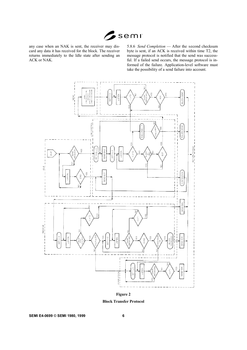
5.8 Algorithm — The operation of the block transfer
protocol is best understood by following the logic flow
in Figure 2. This flow chart depicts the operation of the
five states of the protocol - Receive, Idle, Send Line
Control, and Completion. The flow chart shown in Fig-
ure 2 is not meant to imply that a particular implemen-
tation is required under this standard. However, any
SECS-I block transfer protocol implementation must in-
clude all the logic described in Figure 2. The same
algorithm is executed on each end of the SECS-I
communications link.
5.8.1 Idle State — Both ends of the communications
link are assumed to start in the Idle state. There are two
primary activities of the protocol signified by the two
exits from the Idle state. These are:
A. SEND — a message block is to be sent.
B. RECEIVE — the other end of the communications
link has a message block to send
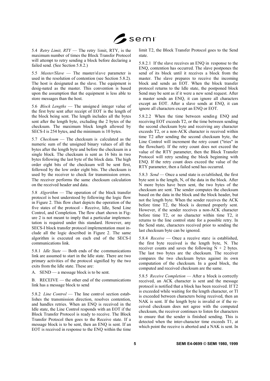
5.8.2 Line Control — The line contr ol section estab-
lishes the transmission direction, resolves contention,
and handles retries. When an ENQ is received in the
Idle state, the Line Control responds with an EOT if the
Block Transfer Protocol is ready to receive. The Block
Transfer Protocol then goes to the Receive state. If a
message block is to be sent, then an ENQ is sent. If an
EOT is received in response to the ENQ within the time
limit T2, the Block Transfer Protocol goes to the Send
state.
5.8.2.1 If the slave receives an ENQ in response to the
ENQ, contention has occurred. The slave postpones the
send of its block until it receives a block from the
master. The slave prepares to receive the incoming
block and sends an EOT. When the block transfer
protocol returns to the Idle state, the postponed block
Send may be sent as if it were a new send request. After
a master sends an ENQ, it can ignore all characters
except an EOT. After a slave sends at ENQ, it can
ignore all characters except an ENQ or EOT.
5.8.2.2 When the time between sendin g ENQ and
receiving EOT exceeds T2, or the time between sending
the second checksum byte and receiving any character
exceeds T2, or a non-ACK character is received within
time T2 after sending the second checksum byte, the
Line Control will increment the retry count ("tries" in
the flowchart). If the retry count does not exceed the
value of the RTY parameter, then the Block Transfer
Protocol will retry sending the block beginning with
ENQ. If the retry count does exceed the value of the
RTY parameter, then a failed send has occurred.
5.8.3 Send — Once a send state is es tablished, the first
byte sent is the length, N, of the data in the block. After
N more bytes have been sent, the two bytes of the
checksum are sent. The sender computes the checksum
based on the data in the block and the block header, but
not the length byte. When the sender receives the ACK
before time T2, the block is deemed properly sent.
However, if the sender receives a non-ACK character
before time T2, or no character within time T2, it
returns to the line control state for a possible retry. In
the Send state, characters received prior to sending the
last checksum byte can be ignored.
5.8.4 Receive — Once a receive stat e is established,
the first byte received is the length byte, N. The
receiver counts and saves the following N + 2 bytes.
The last two bytes are the checksum. The receiver
compares the two checksum bytes against its own
computation of the checksum. In a good block, the
computed and received checksum are the same.
5.8.5 Receive Completion — After a block is correctly
received, an ACK character is sent and the message
protocol is notified that a block has been received. If T2
is exceeded while waiting for the length character, or Tl
is exceeded between characters being received, then an
NAK is sent. If the length byte is invalid or if the re-
ceived checksum does not agree with the computed
checksum, the receiver continues to listen for characters
to ensure that the sender is finished sending. This is
detected when the inter-character time exceeds T1, at
which point the receive is aborted and a NAK is sent. In
5
SEMI E4-0699 © SEMI 1980, 1999
�
any case when an NAK is sent, the receiver may dis-
card any data it has received for the block. The receiver
returns immediately to the Idle state after sending an
ACK or NAK.
5.8.6 Send Completion — After the second checksum
byte is sent, if an ACK is received within time T2, the
message protocol is notified that the send was success-
ful. If a failed send occurs, the message protocol is in-
formed of the failure. Application-level software must
take the possibility of a send failure into account.
Figure 2
Block Transfer Protocol
SEMI E4-0699 © SEMI 1980, 1999
6
�
6 Header Structure
is
linked
the block
transfer protocol
6.1 The operation of all communic ations functions
above
to
information contained in a 10-byte data element called
the header. The header is always the first 10 bytes of
every block sent by the block transfer protocol. The
information in the header is also used by the message
protocol (see Section 7). The fixed format of the header
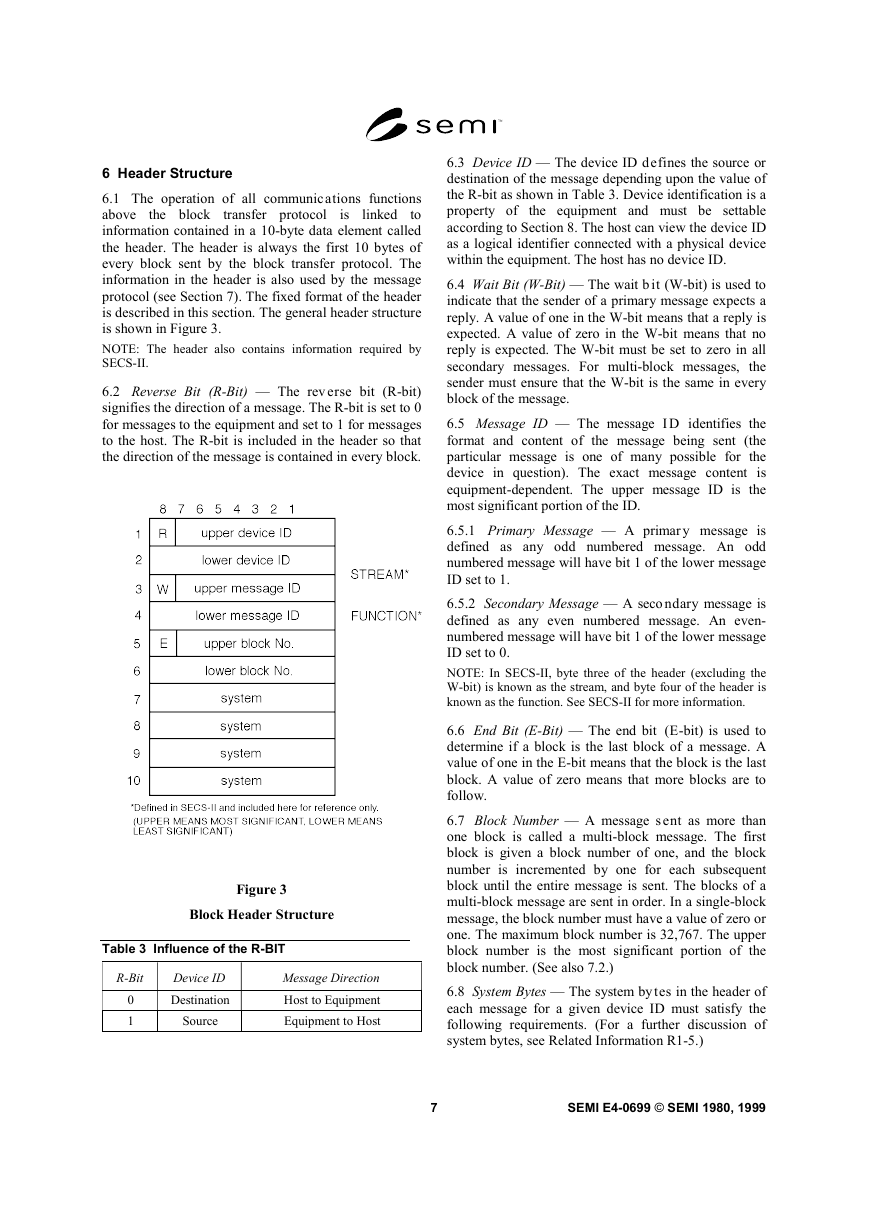
is described in this section. The general header structure
is shown in Figure 3.
NOTE: The header also contains information required by
SECS-II.
6.2 Reverse Bit (R-Bit) — The rev erse bit (R-bit)
signifies the direction of a message. The R-bit is set to 0
for messages to the equipment and set to 1 for messages
to the host. The R-bit is included in the header so that
the direction of the message is contained in every block.
Figure 3
Block Header Structure
Table 3 Influence of the R-BIT
R-Bit
Device ID
Message Direction
0
1
Destination
Source
Host to Equipment
Equipment to Host
6.3 Device ID — The device ID defines the source or
destination of the message depending upon the value of
the R-bit as shown in Table 3. Device identification is a
property of the equipment and must be settable
according to Section 8. The host can view the device ID
as a logical identifier connected with a physical device
within the equipment. The host has no device ID.
6.4 Wait Bit (W-Bit) — The wait b it (W-bit) is used to
indicate that the sender of a primary message expects a
reply. A value of one in the W-bit means that a reply is
expected. A value of zero in the W-bit means that no
reply is expected. The W-bit must be set to zero in all
secondary messages. For multi-block messages, the
sender must ensure that the W-bit is the same in every
block of the message.
6.5 Message ID — The message I D identifies the
format and content of the message being sent (the
particular message is one of many possible for the
device in question). The exact message content is
equipment-dependent. The upper message ID is the
most significant portion of the ID.
6.5.1 Primary Message — A primar y message is
defined as any odd numbered message. An odd
numbered message will have bit 1 of the lower message
ID set to 1.
6.5.2 Secondary Message — A seco ndary message is
defined as any even numbered message. An even-
numbered message will have bit 1 of the lower message
ID set to 0.
NOTE: In SECS-II, byte three of the header (excluding the
W-bit) is known as the stream, and byte four of the header is
known as the function. See SECS-II for more information.
6.6 End Bit (E-Bit) — The end bit (E-bit) is used to
determine if a block is the last block of a message. A
value of one in the E-bit means that the block is the last
block. A value of zero means that more blocks are to
follow.
6.7 Block Number — A message s ent as more than
one block is called a multi-block message. The first
block is given a block number of one, and the block
number is incremented by one for each subsequent
block until the entire message is sent. The blocks of a
multi-block message are sent in order. In a single-block
message, the block number must have a value of zero or
one. The maximum block number is 32,767. The upper
block number is the most significant portion of the
block number. (See also 7.2.)
6.8 System Bytes — The system bytes in the header of
each message for a given device ID must satisfy the
following requirements. (For a further discussion of
system bytes, see Related Information R1-5.)
7
SEMI E4-0699 © SEMI 1980, 1999
�
6.8.1 Distinction — The system byt es of a primary
message must be distinct from those of all currently
open transactions initiated from the same end of the
communications link. They must also be distinct from
those of the most recently completed transaction. (See
Section 7.3.) They must also be distinct from any
system bytes of blocks that were not successfully sent
since the last successful block send.
6.8.2 Reply Message — The system bytes of the reply
message are required to be the same as the system bytes
of the corresponding primary message.
6.8.3 Multi-Block Messages — The system bytes of all
blocks of a multi-block message must be the same.
7 Message Protocol
7.1 A message is a complete unit o f communication in
one direction. The message protocol uses the services
of the block transfer protocol to send and receive
messages. The message consists of the message data
together with the following information from the header
— R-bit, device ID, W-bit, message ID, and system
bytes.
7.2 Message Send — When a mes sage is ready to be
sent, the message send protocol performs the functions
described below. A block send failure terminates the
message protocol action on that message.
7.2.1 Message Length — The maximum data length in
a single block of a message is 244 bytes. The maximum
number of blocks that can be sent in a multi-block
message is 32,767, and so the maximum data length
allowed in one message is 244 × 32,767 bytes.
7.2.2 Message Blocking — Message blocking is the
division of the message data into blocks to be sent to
the Block Transfer Protocol. For best performance, it is
recommended, but not required, that the sender fill all
blocks of a multi-block message, except possibly the
last block, with the maximum 254 bytes. The receiver
of a multi-block message should be able to accept any
block size from 11 to 254 bytes, and should not require
consecutive blocks necessarily to be the same size.
7.2.2.1 Certain older implementations may impose
application-specific requirements on block sizes for
certain incoming messages. Beginning with the 1988
revision of the standard, new applications may not
impose application-specific requirements on incoming
block sizes. Applications implemented before 1988
may impose such requirements.
NOTE: In SECS-II, certain messages are defined as single-
block messages and must be sent as a single block in SECS-I.
7.2.3 Header — The message protocol must establish
the header in each block of the message according to
the requirements of Section 6.
7.2.4 Interleaving Messages — This standard allows,
but does not require, the support of more than one
concurrent open transaction. This standard allows, but
does not require, the support of interleaving the blocks
of different multi-block messages. (See documentation
requirements in 9.)
7.3 Transactions — A transaction
is a primary
message and an optional corresponding secondary
message is called the reply. A transaction is opened
when a primary message is ready to be sent. A
transaction is closed when the last block of a primary
message requesting no reply has been sent, or when the
last block of the reply has been received.
7.3.1 Reply Linking — When a reply is expected for a
primary message, the message protocol starts the reply
timer for the transaction after the last block of the
message is successfully sent. When a primary message
is sent for which a reply is requested, an expected block
is established for the message receive algorithm. (See
Section 7.4.) The expected block will have
the
complement of the R-bit, will have the same device ID,
will be the first block of a secondary message, and will
have the same system bytes as those of the given
primary message.
NOTE: In SECS-II, the reply will have the same upper
message ID (stream), and the lower message ID (function)
will either be one greater than that of the corresponding
primary message, or it will be zero.
7.3.2 Reply Timeout, T3 — The repl y timeout, T3, is a
limit on the length of time that the message protocol is
willing to wait after the last block of a primary message
has been sent and before the arrival of the first block of
the reply. If the first block of the reply does not arrive
within the T3 limit, the expected block is removed from
the list of expected blocks, and the transaction is
aborted. A timer, called the reply timer, is used to
measure the time between the last block of the primary
message and the first block of its reply. Each open
transaction for which a reply is expected requires a
separate reply timer.
7.4 Message Receive — Each bloc k successfully
received by the block transfer protocol is passed to the
message protocol. It is the task of the message protocol
to identify the blocks and assemble them into the proper
message.
7.4.1 Routing Error — When a piece of equipment
receives a block of data which has a device ID in the
block header which does not match its own device ID
and it has no other knowledge of this device ID, it can
assume that the block was sent in error.
SEMI E4-0699 © SEMI 1980, 1999
8
�




 2023年江西萍乡中考道德与法治真题及答案.doc
 2012年重庆南川中考生物真题及答案.doc
 2013年江西师范大学地理学综合及文艺理论基础考研真题.doc
 2020年四川甘孜小升初语文真题及答案I卷.doc
 2020年注册岩土工程师专业基础考试真题及答案.doc
 2023-2024学年福建省厦门市九年级上学期数学月考试题及答案.doc
 2021-2022学年辽宁省沈阳市大东区九年级上学期语文期末试题及答案.doc
 2022-2023学年北京东城区初三第一学期物理期末试卷及答案.doc
 2018上半年江西教师资格初中地理学科知识与教学能力真题及答案.doc
 2012年河北国家公务员申论考试真题及答案-省级.doc
 2020-2021学年江苏省扬州市江都区邵樊片九年级上学期数学第一次质量检测试题及答案.doc
 2022下半年黑龙江教师资格证中学综合素质真题及答案.doc