logo资料库

松下RTEX 专用IC MNM1221 datasheet.pdf

第1页 / 共102页
第2页 / 共102页
第3页 / 共102页
第4页 / 共102页
第5页 / 共102页
第6页 / 共102页
第7页 / 共102页
第8页 / 共102页
资料共102页,剩余部分请下载后查看
Title Page
Table of Contents
Chapter 1 General Description
Overview
Introduction
Features
Applications
System Diagram
Detail of a Node
Block Diagram of MNM1221
Pin Descriptions
Pin Assignments
Master Pin Descriptions
Slave Pin Descriptions
Operating Mode Settings
Connection to PHY with MII
Chapter 2 Master Operation
Connection for Master Operation
Mode Setting
Bus interface between MNM1221 and CPU
Functional Description
State Transition of MNM1221
Descriptions of Each State
Time Chart at Start-up
Transmission in RUNNING State
TX and RX Memory in MNM1221
Assignment on TX and RX Memory
Memory Map
Registers Description
Table of Registers
(1) Control Registers for Master
(2) Status Registers for Master
Chip Reset
Initial Frame Transmit
Cyclic Transmission Start
Real-Time Frame Format
Error Counter Setting
Initializing Done
Transmit Timing Select
Transmission Period
Transmission Memory Switch
Receiving Memory Hold
Communication State
Initializing Error
Error Flags 1 (Errors at RING CONFIG)
Error Flags 2 (Errors at RUNNING)
Data CRC Errors
Slave Node Sum
Data Block Sum
Slave Information
MII Register Access
Table of Registers
(1) Control Registers
(2) Status Register
MDIO Write Data
MDIO Address
MDIO Write Command
MDIO Read Command
MDIO Read Data
Chapter 3 Slave Operation
Overview
Introduction
Features in Slave
CPU
Connection for Slave
Bus Interface with CPU in Generic slave
Connection for IN slave
Connection for OUT slave
Functional Description
State Transition of MNM1221
Descriptions of Each State
Time Chart at Start-up
Timing Signal Output
Transmission in RUNNING state
TX and RX Memory in MNM1221
Location in TX and RX Memory
Memory Map
Registers Description
Table of Registers
(1) Control Registers for Slave
(2) Status Registers for Slave
Chip Reset
MAC-ID Setting
Number of Occupied Blocks
Timeout Setting
Initializing Done
INTRX Mask at Timeout
SYNC Output Delay
SYNC Output Mask
Transmission Memory Switch
Receiving Memory Hold
Communication State
Over Number of Slave
Error Flags
Data CRC Errors (L)
Data CRC Errors (H)
My Node Order
My Block Order
Slave Node Sum
Data Block Sum
MII Register Access
Table of Registers
(1) Control Registers
(2) Status Register
MDIO Write Data
MDIO Address
MDIO Write Command
MDIO Read Command
MDIO Read Data
Chapter 4 Common to Master and Slave
Electrical Characteristics
Absolute Maximum Ratings
Recommended Operating Conditions
Value
DC Characteristics
Value
Unit
AC Characteristics
(1) Clock Input IXTAL
(2) Read Access Timing
(3) Write Access Timing
Dimensions
Soldering Information
Ordering Information
MNM1221 100Mbps Communication ASIC For RTEX Datasheet MNM1221 Datasheet CONFIDENTIAL - 1 - 2011/9/13 Rev. 1
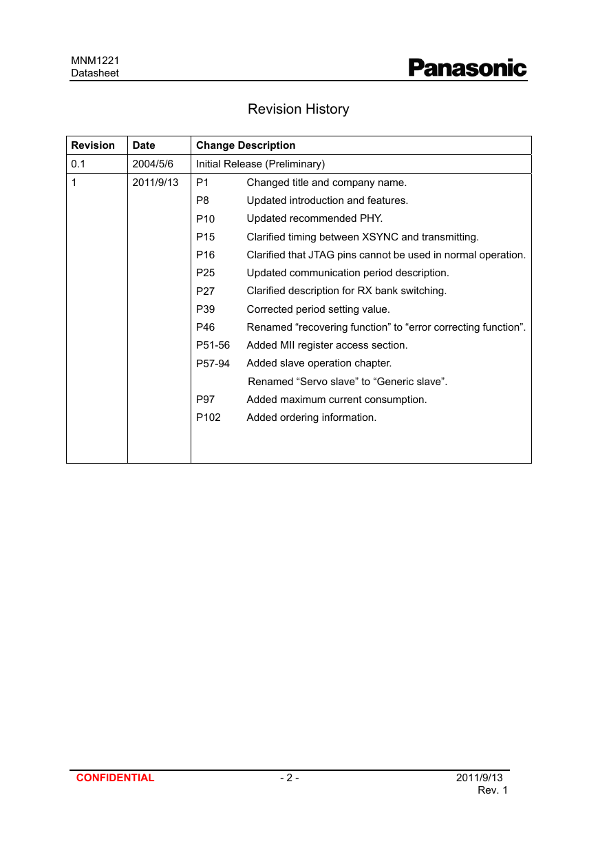
MNM1221 Datasheet Revision Date 0.1 1 2004/5/6 2011/9/13 Revision History Change Description Initial Release (Preliminary) P1 P8 P10 P15 P16 P25 P27 P39 P46 P51-56 P57-94 Changed title and company name. Updated introduction and features. Updated recommended PHY. Clarified timing between XSYNC and transmitting. Clarified that JTAG pins cannot be used in normal operation. Updated communication period description. Clarified description for RX bank switching. Corrected period setting value. Renamed “recovering function” to “error correcting function”. Added MII register access section. Added slave operation chapter. Renamed “Servo slave” to “Generic slave”. Added maximum current consumption. Added ordering information. P97 P102 CONFIDENTIAL - 2 - 2011/9/13 Rev. 1
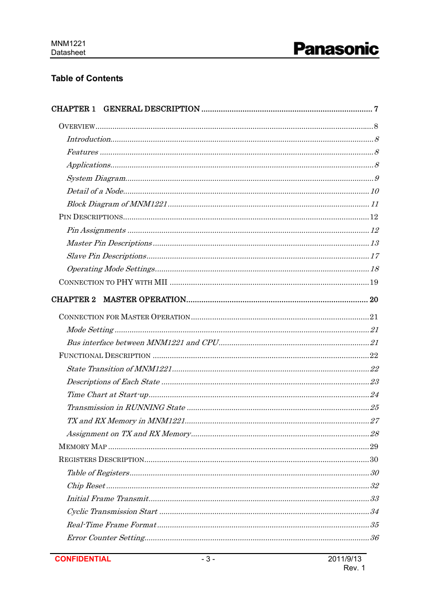
MNM1221 Datasheet Table of Contents CHAPTER 1 GENERAL DESCRIPTION ............................................................................... 7 OVERVIEW...................................................................................................................................8 Introduction............................................................................................................................8 Features.................................................................................................................................8 Applications............................................................................................................................8 System Diagram.....................................................................................................................9 Detail of a Node....................................................................................................................10 Block Diagram of MNM1221...............................................................................................11 PIN DESCRIPTIONS....................................................................................................................12 Pin Assignments.................................................................................................................12 . Master Pin Descriptions......................................................................................................13 Slave Pin Descriptions.........................................................................................................17 Operating Mode Settings.....................................................................................................18 CONNECTION TO PHY WITH MII ..............................................................................................19 CHAPTER 2 MASTER OPERATION.................................................................................... 20 CONNECTION FOR MASTER OPERATION....................................................................................21 Mode Setting........................................................................................................................21 Bus interface between MNM1221 and CPU.......................................................................21 FUNCTIONAL DESCRIPTION ......................................................................................................22 State Transition of MNM1221.............................................................................................22 Descriptions of Each State..................................................................................................23 Time Chart at Start-up........................................................................................................24 Transmission in RUNNING State......................................................................................25 TX and RX Memory in MNM1221.......................................................................................27 Assignment on TX and RX Memory....................................................................................28 MEMORY MAP ...........................................................................................................................29 REGISTERS DESCRIPTION..........................................................................................................30 Table of Registers.................................................................................................................30 Chip Reset............................................................................................................................32 Initial Frame Transmit........................................................................................................33 Cyclic Transmission Start...................................................................................................34 Real-Time Frame Format....................................................................................................35 Error Counter Setting..........................................................................................................36 CONFIDENTIAL - 3 - 2011/9/13 Rev. 1
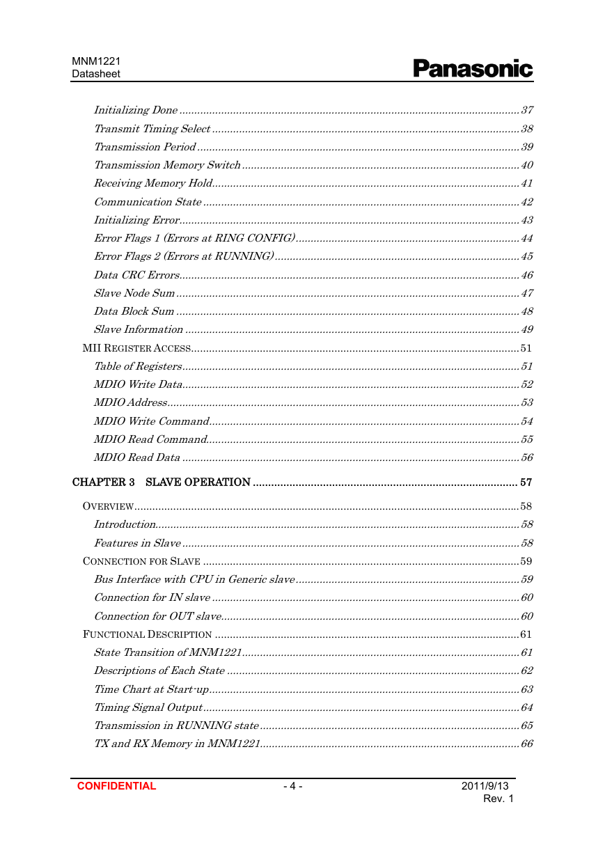
MNM1221 Datasheet Initializing Done..................................................................................................................37 Transmit Timing Select.......................................................................................................38 Transmission Period............................................................................................................39 Transmission Memory Switch.............................................................................................40 Receiving Memory Hold.......................................................................................................41 Communication State..........................................................................................................42 Initializing Error..................................................................................................................43 Error Flags 1 (Errors at RING CONFIG)...........................................................................44 Error Flags 2 (Errors at RUNNING)..................................................................................45 Data CRC Errors.................................................................................................................46 . Slave Node Sum..................................................................................................................47 Data Block Sum..................................................................................................................48 Slave Information...............................................................................................................49 MII REGISTER ACCESS..............................................................................................................51 Table of Registers.................................................................................................................51 MDIO Write Data.................................................................................................................52 MDIO Address......................................................................................................................53 MDIO Write Command........................................................................................................54 MDIO Read Command.........................................................................................................55 MDIO Read Data.................................................................................................................56 . . . CHAPTER 3 SLAVE OPERATION ....................................................................................... 57 OVERVIEW.................................................................................................................................58 Introduction..........................................................................................................................58 Features in Slave.................................................................................................................58 CONNECTION FOR SLAVE ..........................................................................................................59 Bus Interface with CPU in Generic slave...........................................................................59 Connection forIN slave.......................................................................................................60 Connection for OUT slave....................................................................................................60 FUNCTIONAL DESCRIPTION ......................................................................................................61 State Transition of MNM1221.............................................................................................61 Descriptions of Each State..................................................................................................62 Time Chart at Start-up........................................................................................................63 Timing Signal Output..........................................................................................................64 Transmission in RUNNING state.......................................................................................65 TX and RX Memory in MNM1221.......................................................................................66 CONFIDENTIAL - 4 - 2011/9/13 Rev. 1
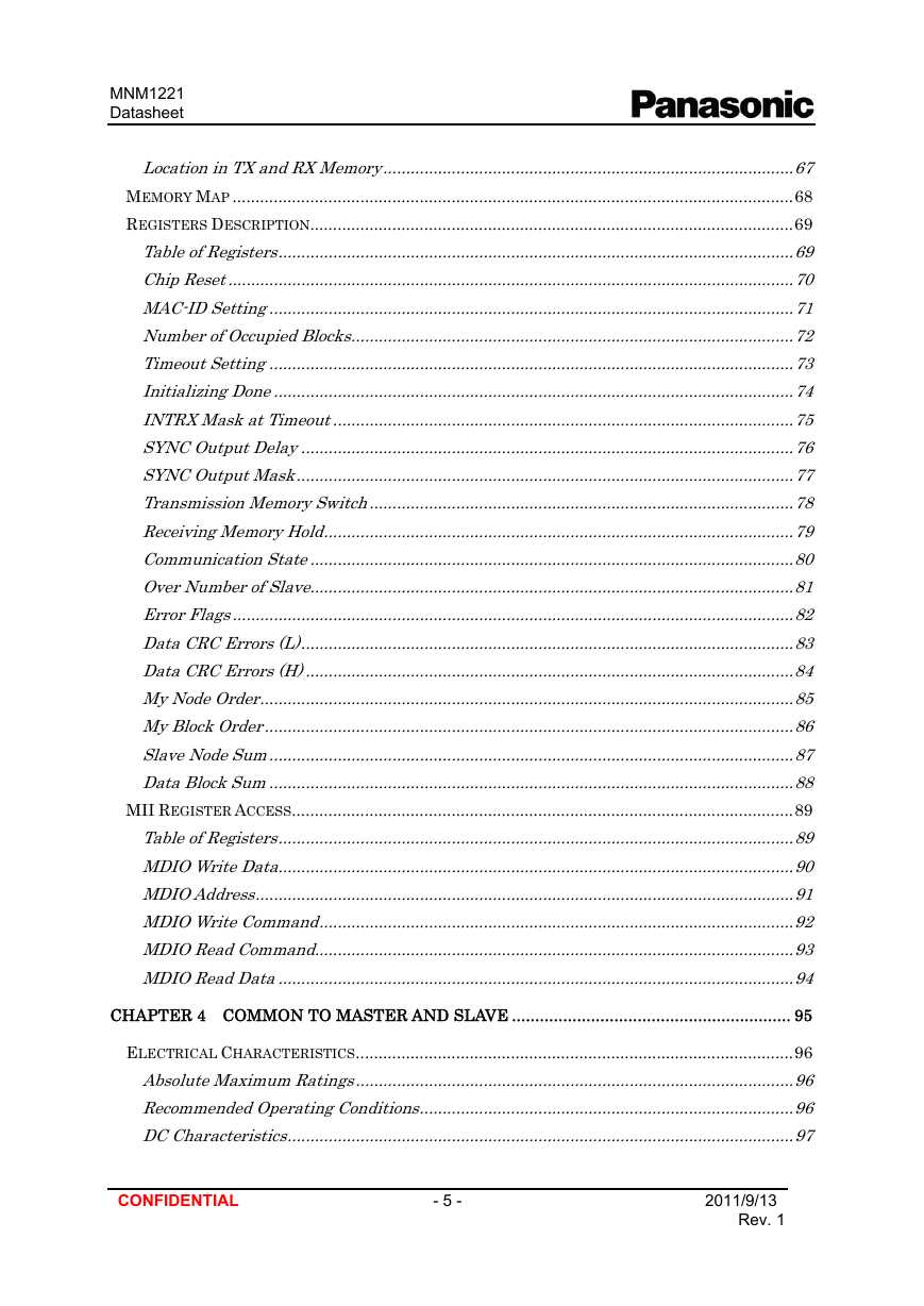
MNM1221 Datasheet . Location in TX and RX Memory..........................................................................................67 MEMORY MAP ...........................................................................................................................68 REGISTERS DESCRIPTION..........................................................................................................69 Table of Registers.................................................................................................................69 Chip Reset............................................................................................................................70 MAC-IDSetting..................................................................................................................71 Number of Occupied Blocks.................................................................................................72 Timeout Setting...................................................................................................................73 Initializing Done..................................................................................................................74 INTRX Mask at Timeout.....................................................................................................75 SYNC Output Delay............................................................................................................76 SYNC Output Mask.............................................................................................................77 Transmission Memory Switch.............................................................................................78 Receiving Memory Hold.......................................................................................................79 Communication State..........................................................................................................80 Over Number of Slave..........................................................................................................81 Error Flags...........................................................................................................................82 Data CRC Errors (L)............................................................................................................83 Data CRC Errors (H)...........................................................................................................84 My Node Order.....................................................................................................................85 My Block Order....................................................................................................................86 Slave Node Sum..................................................................................................................87 Data Block Sum..................................................................................................................88 MII REGISTER ACCESS..............................................................................................................89 Table of Registers.................................................................................................................89 MDIO Write Data.................................................................................................................90 MDIO Address......................................................................................................................91 MDIO Write Command........................................................................................................92 MDIO Read Command.........................................................................................................93 MDIO Read Data.................................................................................................................94 . . CHAPTER 4 COMMON TO MASTER AND SLAVE ............................................................ 95 ELECTRICAL CHARACTERISTICS................................................................................................96 Absolute Maximum Ratings................................................................................................96 Recommended Operating Conditions..................................................................................96 DC Characteristics..............................................................................................................97 . CONFIDENTIAL - 5 - 2011/9/13 Rev. 1
MNM1221 Datasheet AC Characteristics..............................................................................................................98 . DIMENSIONS ...........................................................................................................................101 SOLDERING INFORMATION......................................................................................................101 ORDERING INFORMATION........................................................................................................102 CONFIDENTIAL - 6 - 2011/9/13 Rev. 1
MNM1221 Datasheet Chapter 1 General Description CONFIDENTIAL - 7 - 2011/9/13 Rev. 1
MNM1221 Datasheet Introduction Overview “Realtime Express (RTEX)” based upon MNM1221 is a serial interface controller ASIC that enables to establish the real-time the master-slaves communication systems communication style with the ring topology. The MNM1221 requires to be used with a PHY (PHYsical layer chip), a pulse transformer and shielded twisted pair cables for 100BASE-TX (IEEE 802.3u) system. In other words, MNM1221 is a special MAC(Media Access Controller) in order to suit 100BASE-TX to real-time communication system for the multi-axis servo control. The MNM1221 serial interface system consists of one master and several slaves, and exchanges the command data from the master and the response data from the slave cyclically. For that, MNM1221 has double banks (buffer) memory for each transmitting and receiving, and this function allows the CPU to operate efficiently. Features - Connected to the PHY with MII (Media Independent Interface) by IEEE 802.3u - Ring topology - 100Mbps Full-Duplex - For both master and slave mode operation - Maximum 32 slaves - Double banks (buffer) memory, size of 512 bytes each for RX and TX. - Data bus for CPU interface: - Data error detection based on CRC-CCITT(16bits CRC) - 25MHz clock same as driving PHY - 3.3V operation and partly with 5V tolerant pins for CPU interface - -40 to +85 degree C operating ambient - 100pins plastic LQFP package of Pb-Free Master: 32-bit or 16-bit wide Slave: 16-bit or 8-bit wide Applications - High performance multi-axis servo control systems CONFIDENTIAL - 8 - 2011/9/13 Rev. 1
分享到:
收藏